ECO mode MITSUBISHI MIRAGE G4 2020 (in English) Service Manual
[x] Cancel search | Manufacturer: MITSUBISHI, Model Year: 2020, Model line: MIRAGE G4, Model: MITSUBISHI MIRAGE G4 2020Pages: 253, PDF Size: 36.39 MB
Page 175 of 253
Automatic air conditioning 7-8 Comfort controls
7
N00737301409
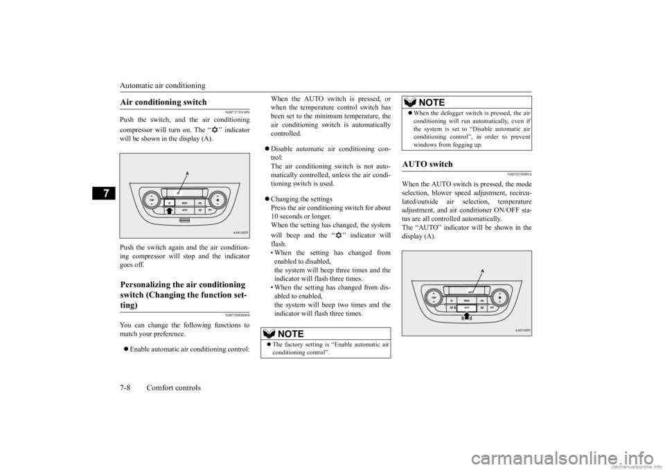
Push the switch, and the air conditioning compressor will turn on. The “ ” indicator will be shown in the display (A). Push the switch again and the air condition- ing compressor will stop and the indicator goes off.
N00759800090
You can change the following functions tomatch your preference. Enable automatic air conditioning control:
When the AUTO switch is pressed, or when the temperature control switch hasbeen set to the minimum temperature, the air conditioning switch
is automatically
controlled. Disable automatic air conditioning con- trol: The air conditioning switch is not auto- matically controlled, unless the air condi-tioning switch is used. Changing the settings Press the air conditi
oning switch for about
10 seconds or longer. When the setting has changed, the system will beep and the “ ” indicator will flash.• When the setting has changed from enabled to disabled, the system will beep three times and theindicator will flash three times. • When the setting has changed from dis- abled to enabled,the system will beep two times and the indicator will flash three times.
N00703500016
When the AUTO switch is pressed, the modeselection, blower spee
d adjustment, recircu-
lated/outside air sele
ction, temperature
adjustment, and air conditioner ON/OFF sta- tus are all controlled automatically. The “AUTO” indicator
will be shown in the
display (A).
Air conditioning switch Personalizing the air conditioning switch (Changing the function set- ting)
NOTE
The factory setting is
“Enable automatic air
conditioning control”.
When the defogger switch is pressed, the air conditioning will run au
tomatically, even if
the system is set to “Disable automatic airconditioning control”, in order to prevent windows from fogging up.
AUTO switch
NOTE
BK0284300US.book 8 ページ 2019年5月23日 木曜日 午後12時22分
Page 177 of 253
Important air condit
ioning operating tips
7-10 Comfort controls
7
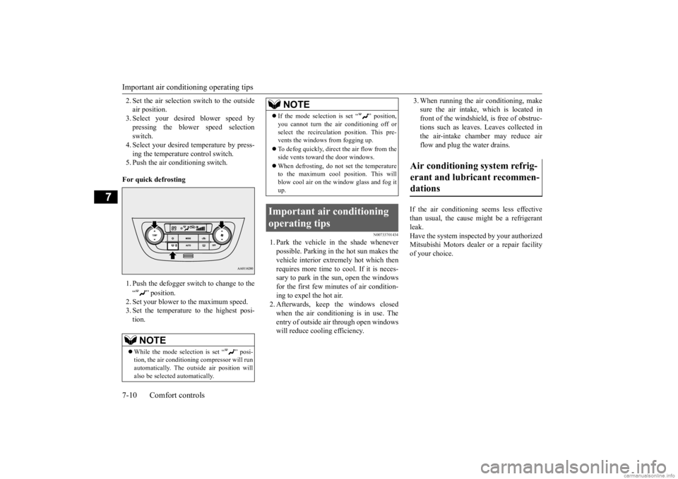
2. Set the air selection switch to the outside air position.3. Select your desired blower speed by pressing the blower speed selection switch.4. Select your desired temperature by press- ing the temperature control switch. 5. Push the air conditioning switch. For quick defrosting 1. Push the defogger switch to change to the “ ” position. 2. Set your blower to the maximum speed.3. Set the temperature to the highest posi- tion.
N00733701434
1. Park the vehicle in the shade whenever possible. Parking in the hot sun makes the vehicle interior extremely hot which then requires more time to cool. If it is neces-sary to park in the sun, open the windows for the first few minutes of air condition- ing to expel the hot air.2. Afterwards, keep the windows closed when the air conditioning is in use. The entry of outside air through open windowswill reduce cooling efficiency.
3. When running the air conditioning, make sure the air intake, which is located infront of the windshield, is free of obstruc- tions such as leaves. Leaves collected in the air-intake chamber may reduce airflow and plug the water drains.
If the air conditioning seems less effective than usual, the cause might be a refrigerant leak. Have the system inspected by your authorizedMitsubishi Motors dealer
or a repair facility
of your choice.
NOTE
While the mode selection is set “ ” posi- tion, the air conditioning
compressor will run
automatically. The out
side air position will
also be selected automatically.
If the mode selection is set “ ” position, you cannot turn the air conditioning off orselect the recirculati
on position. This pre-
vents the windows from fogging up. To defog quickly, direct the air flow from the side vents toward the door windows. When defrosting, do not set the temperature to the maximum cool position. This will blow cool air on the window glass and fog it up.
Important air conditioning operating tips
NOTE
Air conditioning system refrig- erant and lubricant recommen- dations
BK0284300US.book 10 ページ 2019年5月23日 木曜日 午後12時22分
Page 178 of 253
Air purifier
Comfort controls 7-11
7
The air conditioning should be operated for at least five minutes each week, even in cold weather. This includes the quick defrostingmode. Operating the
air condition system
weekly maintains lubrication of the compres- sor internal parts to keep the air conditioningin the best operating condition.
N00733801246
The air conditioning syst
em is equipped with
an air filter to remove pollen and dust.
The air filter’s ability to collect pollen and dirt is reduced as it be
comes dirty, so replace
it periodically. For the maintenance interval, refer to the “WARRANTY AND MAINTE- NANCE MANUAL”.
N00734201553
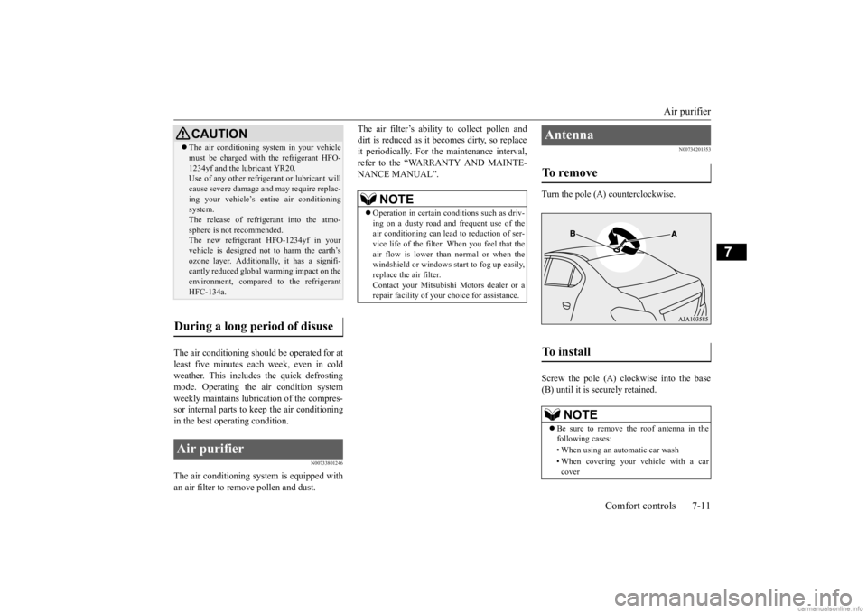
Turn the pole (A) counterclockwise. Screw the pole (A) clockwise into the base (B) until it is securely retained.
CAUTION The air conditioning system in your vehicle must be charged with the refrigerant HFO-1234yf and the lubricant YR20.Use of any other refrigerant or lubricant will cause severe damage a
nd may require replac-
ing your vehicle’s en
tire air conditioning
system. The release of refrigerant into the atmo- sphere is not recommended.The new refrigerant HFO-1234yf in your vehicle is designed not
to harm the earth’s
ozone layer. Additionall
y, it has a signifi-
cantly reduced global
warming impact on the
environment, compared to the refrigerant HFC-134a.
During a long period of disuse Air purifier
NOTE
Operation in certain conditions such as driv- ing on a dusty road and frequent use of the air conditioning ca
n lead to reduction of ser-
vice life of the filter. When you feel that theair flow is lower than normal or when the windshield or windows st
art to fog up easily,
replace the air filter.Contact your Mitsubishi
Motors dealer or a
repair facility of your
choice for assistance.
Antenna To remove To install
NOTE
Be sure to remove the roof antenna in the following cases: • When using an automatic car wash• When covering your ve
hicle with a car
cover
BK0284300US.book 11 ページ 2019年5月23日 木曜日 午後12時22分
Page 184 of 253
Jump-starting the engine For emergencies 8-3
8
3. You could be injured if the vehicles move. Set the parking brake firmly on each vehi-cle. Put an automatic transaxle or CVT in “P” (PARK) or a manual transaxle in “N” (Neutral).4. Turn the ignition switch to the “OFF” position or put the operation mode in OFF. 5. Make sure your batt
ery electrolyte is at
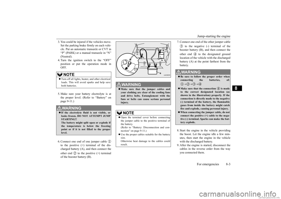
the proper level. (Refer to “Battery” on page 9-11.) 6. Connect one end of one jumper cable to the positive (+) terminal of the dis- charged battery (A),
and then connect the
other end to the positive (+) terminal of the booster battery (B).
7. Connect one end of the other jumper cable
to the negative (-) terminal of the booster battery (B), a
nd then connect the
other end to the designated ground location of the vehicl
e with the discharged
battery (A) at the point farthest from the battery. 8. Start the engine in the vehicle providing the boost. Let the engine idle a few min- utes, then start the engine in the vehiclewith the discharged battery. 9. After the engine is
started, disconnect the
cables in the reverse order from the wayyou connected them.
NOTE
Turn off all lights, heat
er, and other electrical
loads. This will avoid sparks and help save both batteries.WA R N I N G If the electrolyte flui
d is not visible, or
looks frozen, DO NOT ATTEMPT JUMP STARTING!! The battery might split open or explode ifthe temperature is below the freezing point or if it is not filled to the proper level.
WA R N I N G Make sure that the jumper cables and your clothing are clear of the cooling fansand drive belts. Entanglement with the fans or belts can ca
use serious personal
injury.NOTE
Open the terminal cover before connecting the jumper cable to the positive terminal ofthe battery. (Refer to “Battery:
Disconnection and con-
nection” on page 9-11.) Use the proper cables suitable for the battery size.Otherwise heat damage
to the cables could
result.
WA R N I N G Be sure to follow the proper order when connecting the batteries, of:
Make sure that the connection is made to the correct designated location (as shown in the illustration) properly. If theconnection is directly made to the negative (-) terminal of the battery, the flammable gases from inside the battery might catchfire and explode, caus
ing personal injury.
When connecting the jumper cable, do not connect the positive (+) cable to the nega- tive (-) terminal. Sparks can make the bat- tery explode.
BK0284300US.book 3 ページ 2019年5月23日 木曜日 午後12時22分
Page 194 of 253
Operation under adverse driving conditions
For emergencies 8-13
8
Set the gearshift lever to the “N” (Neutral) position.Secure the steering wheel in a straight-ahead position with a rope or tie-down strap. Release the parking brake. Place the gearshift lever in the “N” (Neutral) position (manual transa
xle) or the selector
lever in the “N” (NEUTRAL) position (CVT).
N00837201799
If your vehicle becomes stuck in snow, sand, or mud, it can often be moved by a rockingmotion. Rock your vehicle back and forth to free it.
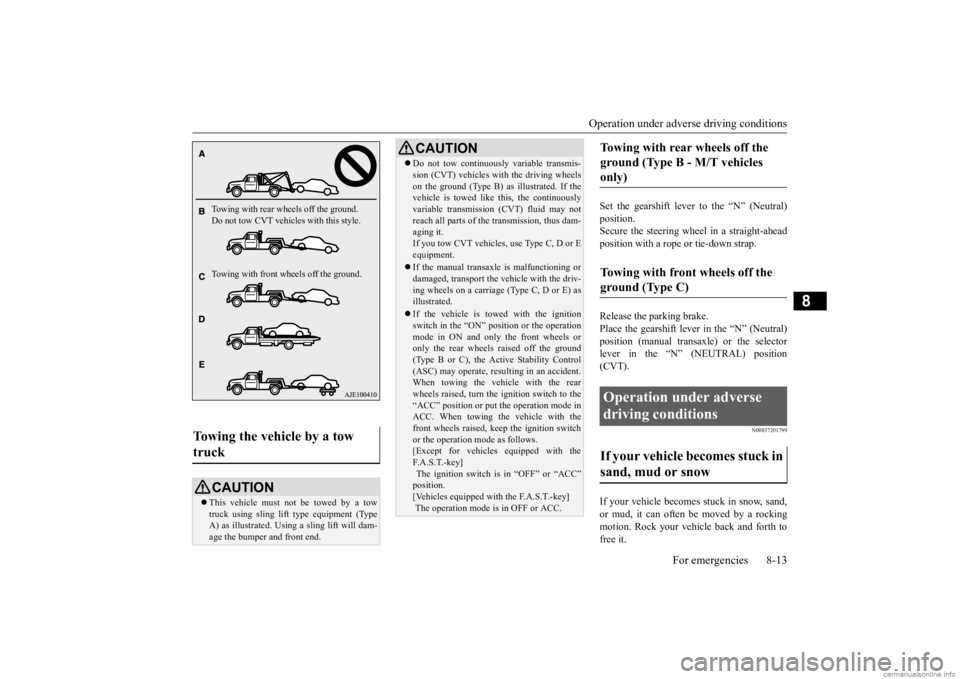
Towing the vehicle by a tow truck
CAUTION This vehicle must not be towed by a tow truck using sling lift
type equipment (Type
A) as illustrated. Using a sling lift will dam- age the bumper and front end.Towing with rear wheels off the ground. Do not tow CVT vehicles with this style. Towing with front wheels off the ground.
Do not tow continuously variable transmis- sion (CVT) vehicles with the driving wheelson the ground (Type B) as illustrated. If thevehicle is towed like
this, the continuously
variable transmission (CVT) fluid may not reach all parts of the transmission, thus dam-aging it. If you tow CVT vehicles, use Type C, D or E equipment. If the manual transaxl
e is malfunctioning or
damaged, transport the
vehicle with the driv-
ing wheels on a carriage (Type C, D or E) as illustrated. If the vehicle is towed with the ignition switch in the “ON” pos
ition or the operation
mode in ON and only the front wheels oronly the rear wheels raised off the ground (Type B or C), the Active Stability Control (ASC) may operate, result
ing in an accident.
When towing the vehicle with the rear wheels raised, turn the ignition switch to the “ACC” position or put
the operation mode in
ACC. When towing the vehicle with the front wheels raised, keep the ignition switch or the operation mode as follows.[Except for vehicles equipped with the F. A . S . T. - k e y ] The ignition switch is
in “OFF” or “ACC”
position. [Vehicles equipped with the F.A.S.T.-key] The operation mode is in OFF or ACC.CAUTION
Towing with rear wheels off the ground (Type B - M/T vehicles only) Towing with front wheels off the ground (Type C) Operation under adverse driving conditions If your vehicle becomes stuck in sand, mud or snow
BK0284300US.book 13 ページ 2019年5月23日 木曜日 午後12時22分
Page 210 of 253

Tires
Vehicle care and maintenance 9-13
9
•The measured pressure after the vehicle has been parked for at least three hours, or•The measured pressure when the vehicle is driven less than 1 mile (1.6 km) after having beenparked for three hours.
Maximum pressure: the maximumpermissible cold tire inflationpressure for this tire.Recommended inflation pressure:the inflation pressure for optimumtire performance.Intended outboard sidewall:•The sidewall that contains awhitewall, bears white lettering or bears manufacturer, brand, and/or model name molding thatis higher or deeper than the same molding on the other sidewall of the tire,or
•The outward facing sidewall ofan asymmetrical tire that has a particular side that must always face outward when mounted on avehicle.
Passenger car tire: a tire intendedfor use on passenger cars, multi-purpose passenger vehicles, and trucks that have a gross vehicle weight rating (GVWR) of 10,000pounds or less.Light truck (LT) tire: a tire desig-nated by its manufacturer as pri-marily intended for use on lightweight trucks or multipurpose passenger vehicles.Tread: portion of a tire that comes into contact with the road.Tread rib: a tread section running circumferentially around a tire.Tread separation: pulling away ofthe tread from the tire carcass.Carcass: the tire structure, excepttread and sidewall rubber which, when inflated, bears the load.Sidewall: portion of a tire between the tread and bead.
Section width: the linear distancebetween the exteriors of the side- walls of an inflated tire, excluding elevations due to labeling, decora-tion, or protective bands.Bead: the part of the tire that ismade of steel wires, wrapped orreinforced by ply cords and that is shaped to fit the rim.Ply: a layer of rubber-coated par- allel cords.Cord: the strands
forming the plies
in the tire.Rim: a metal support for a tire or a tire and tube assembly upon which the tire beads are seated.Rim diameter: nominal diameter of the bead seat.Groove: the space between two adjacent tread ribs.
BK0284300US.book 13 ページ 2019年5月23日 木曜日 午後12時22分
Page 247 of 253
Alphabetical index 12-2
12
Door-ajar warning buzzer
....................
5-77
Door-ajar warning light
.......................
5-77
Doors
Lock
..............................................
5-25
Power door locks
............................
5-27
Driving during cold weather
..................
6-4
Driving, alcohol and drugs
.....................
6-2
E
Electric power steering system (EPS)
...
5-51
Electric rear win
dow defogger switch
...
5-82
Electronic immobilizer (Anti-theft starting system)
.....................................
5-3
, 5-20
Emission-control sy
stem maintenance
..9-21
Engine
Compartment
...................................
9-5
Coolant
...................................
9-7
, 11-6
High coolant temperature warning light
....
5-77 Hood
...............................................
9-4
Model
............................................
11-3
Oil and oil filter
.......................
9-5
, 11-6
Overheating
.....................................
8-4
Serial number
.................................
11-3
Specification
..................................
11-5
Engine hood
.........................................
9-4
Engine switch
.....................................
5-13
Event Data Recording
...........................
3-7
Exhaust system
...................................
9-23
F
Floor mat
.............................................
6-2
Fluid
Brake fluid
.....................................
11-6
Continuously variable
transmission (CVT)
fluid
......................................
9-9
, 11-6
Engine coolant
.........................
9-7
, 11-6
Manual transaxle
.............................
11-6
Washer fluid
............................
9-9
, 11-6
Fluid capacities and lubricants
..............
11-6
Free-hand advanced security transmitter (F.A.S.T.-key)
...................................
5-9
Front fog lights
Bulb capacity
..................................
9-29
Indicators
.......................................
5-75
Replacement
...................................
9-31
Switch
............................................
5-80
Front seat adjustment
............................
4-2
Front side-marker lights
Bulb capacity
..................................
9-29
Replacement
...................................
9-31
Front turn signal lights
Bulb capacity
..................................
9-29
Replacement
...................................
9-31
Fuel
Filling the fuel tank
..........................
3-3
Fuel economy
..................................
6-2
Fuel hoses
......................................
9-22
Fuel remaining warning display
.......
5-69
Fuel selection
...................................
3-2
Tank capacity
.................................
11-6
Fuel Pump Shut-off System
.................
8-15
Fuel remaining display
........................
5-69
Fuses
.................................................
9-24
Fusible links
.......................................
9-24
G
General maintenance
Maintenance
...................................
9-22
General vehicle data
............................
11-3
Genuine Mitsubishi Motors parts
............
3-6
Glove compartment
.............................
5-87
H
Hazard warning flasher switch
.............
5-80
Hazard warning lights
.........................
5-75
Head restraints
......................................
4-5
Headlights
Bulb capacity
.................................
9-29
Dimmer
.........................................
5-79
Headlight flasher
............................
5-79
Switch
...........................................
5-78
High beam indicator
............................
5-75
High coolant temperature warning light 5-77
BK0284300US.book 2 ページ 2019年5月23日 木曜日 午後12時22分
Page 252 of 253

NOTE Name of Owner Date of Purchase
Address of Owner Model of Vehicle
Name and Address of Dealer Vehicle Identification NumberMaintenance record
Service Performed DateKilometers
MilesInspection and Maintenance Item
BK0284300US.book 2 ページ 2019年5月23日 木曜日 午後12時22分