ECU MITSUBISHI MONTERO 1987 1.G User Guide
[x] Cancel search | Manufacturer: MITSUBISHI, Model Year: 1987, Model line: MONTERO, Model: MITSUBISHI MONTERO 1987 1.GPages: 284, PDF Size: 14.74 MB
Page 155 of 284
METERS AND GAUGES - Combination Meter 8-135
.3
16WQ25
16W925
10W926
16F554
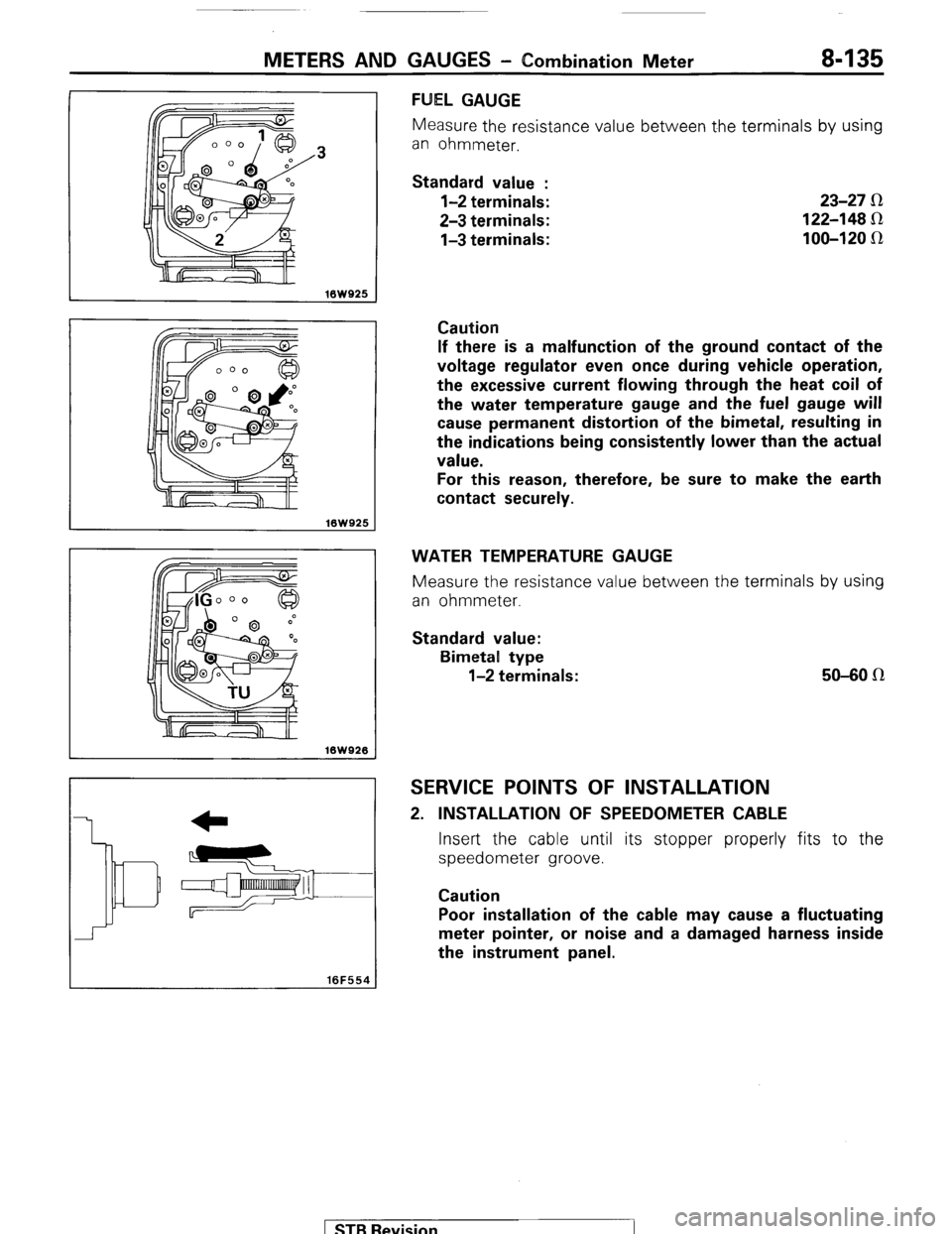
FUEL GAUGE
Measure the resistance value between t.he terminals by using
an ohmmeter.
Standard value :
l-2 terminals:
2-3 terminals:
l-3 terminals: 23-27 R
122-148 Sz
100-120 IR
Caution
If there is a malfunction of the ground contact of the
voltage regulator even once during vehicle operation,
the excessive current flowing through the heat coil of
the water temperature gauge and the fuel gauge will
cause permanent distortion of the bimetal, resulting in
the indications being consistently lower than the actual
value.
For this reason, therefore, be sure to make the earth
contact securely.
WATER TEMPERATURE GAUGE
Measure the resistance value between the terminals by using
an ohmmeter.
Standard value:
Bimetal type
l-2 terminals: 50-80 n
SERVICE POINTS OF INSTALLATION
2. INSTALLATION OF SPEEDOMETER CABLE
Insert the cable until its stopper properly fits to the
speedometer groove.
Caution
Poor installation of the cable may cause a fluctuating
meter pointer, or noise and a damaged harness inside
the instrument panel.
) STB Revision
Page 190 of 284
8-170 WIPER AND WASHER SYSTEM - Service Adjustment Procedures
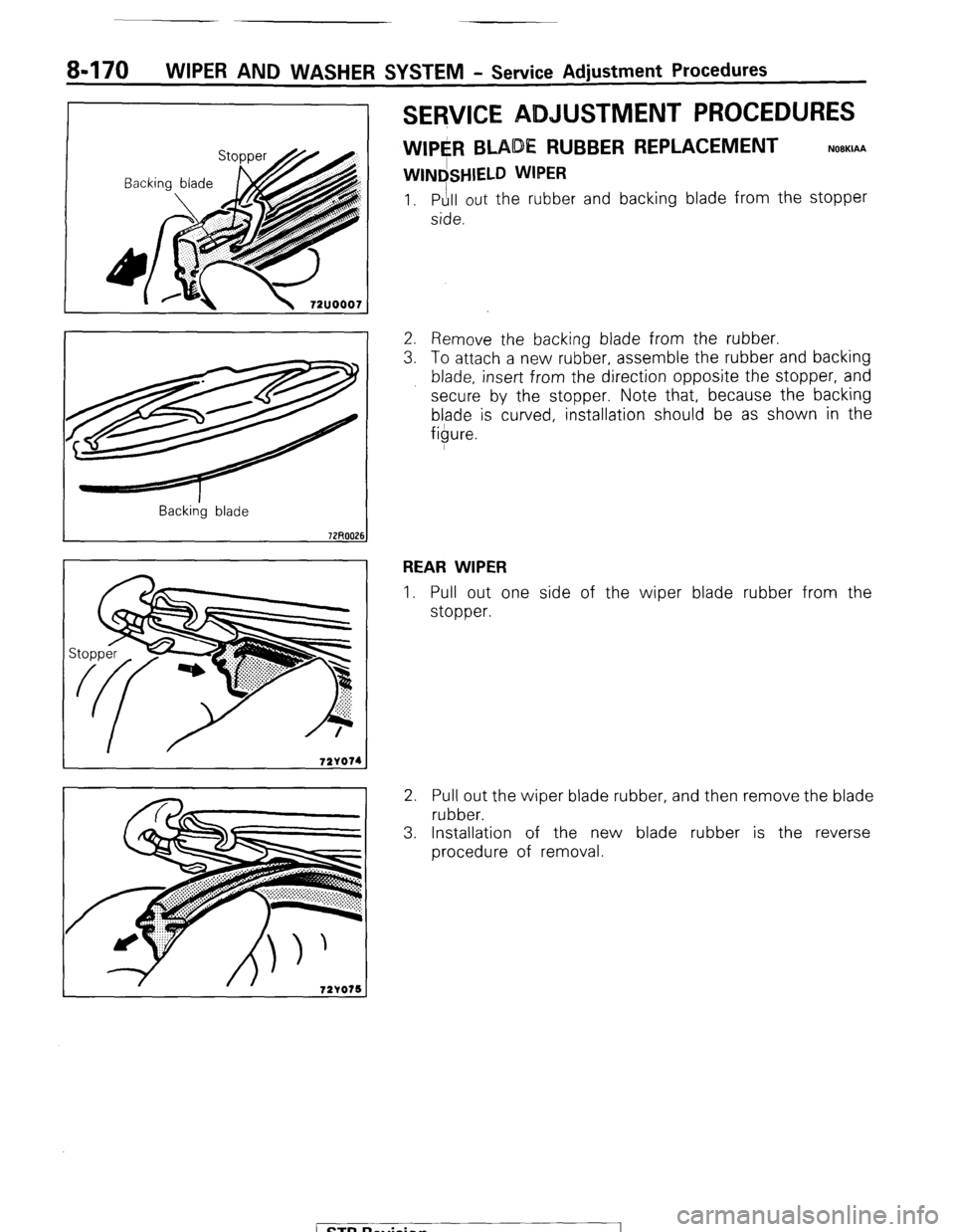
SERVICE ADJUSTMENT PROCEDURES
WIPE#l BLADE RUBBER REPLACEMENT
WINdSHIELD WIPER
NOBKIAA
1. Pull out the rubber and backing blade from the stopper
side.
Back&g blade
2. Remove the backing blade from the rubber.
3. To attach a new rubber, assemble the rubber and backing
blade, insert from the direction opposite the stopper, and
secure by the stopper. Note that, because the backing
blade is curved, installation should be as shown in the
figure.
REAR WIPER
1. Pull out one side of the wiper blade rubber from the
stopper.
2. Pull out the wiper blade rubber, and then remove the blade
rubber.
3. Installation of the new blade rubber is the reverse
procedure of removal.
( ST6 Revision
Page 206 of 284
8486 HORN - Horn
HORN
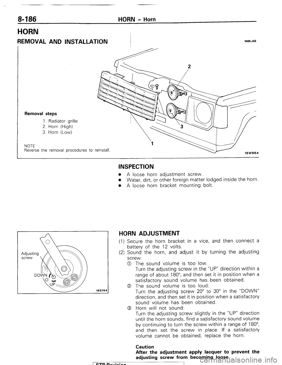
REMOVAL AND INSTALLATION NOBWAE
Removal steps
1. Radiator grille
2. Horn (High)
3. Horn (Low)
NOTE Reverse tne removal procedures to
reinstall.
16W964
169744
INSPECTION o A loose horn adjustment screw.
o Water, dirt, or other foreign matter lodged inside the horn.
l A loose horn bracket mounting bolt.
HORN ADJUSTMENT (1) Secure the horn bracket in a vice, and then connect a
battery of the 12 volts.
(2) Sound the horn, and adjust it by turning the adjusting
screw.
0 The sound volume is too low.
Turn the adjusting screw in the “UP” direction within a
range of about 180”, and then set it in position when a
satisfactory sound volume has been obtained.
0 The sound volume is too loud:
Turn the adjusting screw 20” to 30” in the “DOWN”
direction, and then set it in position when a satisfactory
sound volume has been obtained.
0 Horn will not sound:
Turn the adjusting screw slightly in the “UP” direction
until the horn sounds, find a satisfactory sound volume
by continuing to turn the screw within a range of 180”,
and then set the screw in place. If a satisfactory
volume cannot be obtained, replace the horn.
Caution
After the adjustment apply lacquer to prevent the
adjusting screw from becoming loose.
1 ST6 Revision
Page 221 of 284
AUDIO SYSTEM - Noise Suppression 8-201
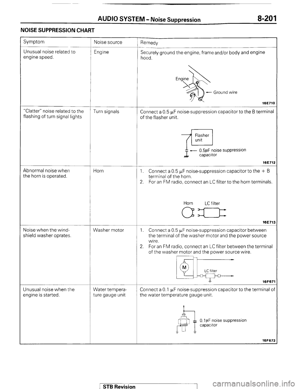
NOISE SUPPRESSION CHART
Symptom
Unusual noise related to
engine speed. ’ Remedy
Securely ground the engine, frame and/or body and engine
hood.
- Ground wire
16E71C
“Clatter” noise related to the
Turn signals
flashing of turn signal lights Connect a 0.5 FF noise-suppression capacitor to the 6 terminal
of the flasher unit.
Abnormal noise when
the horn is operated. Horn ?L - 0.5pF noise suppression
capacitor
16E71:
1. Connect a 0.5 FF noise-suppression capacitor to the + B
terminal of the horn.
2. For an FM radio, connect an LC filter to the horn terminals.
Noise when the wind-
shield washer oprates. Washer motor Horn LC filter
16E71:
1. Connect a 0.5 PF noise-suppression capacitor between
the terminal of the washer motor and the power source
wire.
2. For an FM radio, connect an LC filter between the terminal
of the washer motor and the power source wire.
Unusual noise when the
engine is started. Water tempera-
ture gauge unit Connect a 0.1 p,F noise-suppression capacitor to the terminal o
the water temperature gauge unit.
0.1 PF noise suppression
capacrtor
1 STB Revision
Page 247 of 284
HEATERS - Heater Control 24-11
Top view
Bottom view
I
2OW553
2OW534
2OW750
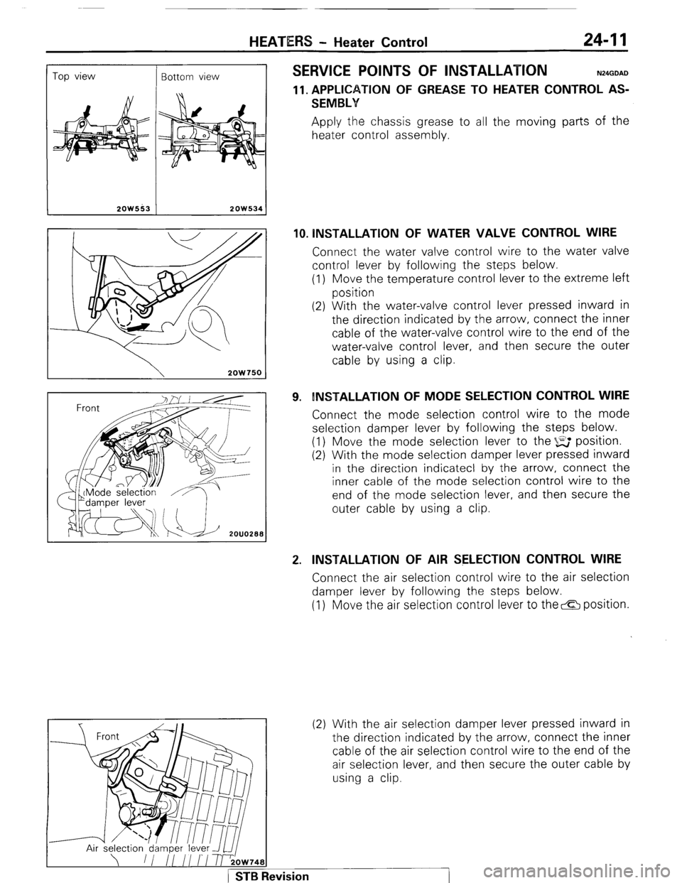
SERVICE POINTS OF INSTALLATION N24GDAD
11. APPLICATION OF GREASE TO HEATER CONTROL AS-
SEMBLY Apply the chassis grease to all the moving parts of the
heater control assembly.
10. lNSTALLATlON OF WATER VALVE CONTROL WIRE Connect the water valve control wire to the water valve
control lever by following the steps below.
(1) Move the temperature control lever to the extreme left
position
(2) With the water-valve control lever pressed inward in
the direction indicated by the arrow, connect the inner
cable of the water-valve control wire to the end of the
water-valve control lever, and then secure the outer
cable by using a clip.
9. INSTALLATION OF MODE SELECTION CONTROL WIRE Connect the mode selection control wire to the mode
selection damper lever by following the steps below.
(1) Move the mode selection lever to the %E position.
(2) With the mode selection damper lever pressed inward
in the direction indicatecl by the arrow, connect the
inner cable of the mode selection control wire to the
end of the mode selection lever, and then secure the
outer cable by using a clip.
2. INSTALLATION OF AIR SELECTION CONTROL WIRE Connect the air selection control wire to the air selection
damper lever by following the steps below.
(1) Move the air selection control lever to the& position.
(2) With the air selection damper lever pressed inward in
the direction indicated by the arrow, connect the inner
cable of the air selection control wire to the end of the
air selection lever, and then secure the outer cable by
using a clip.
1 STB Revision
Page 251 of 284
HEATERS - Blower Assembly 24-15
--I
Front wirina harness
d
!
2OW537
2OW768
2OW779
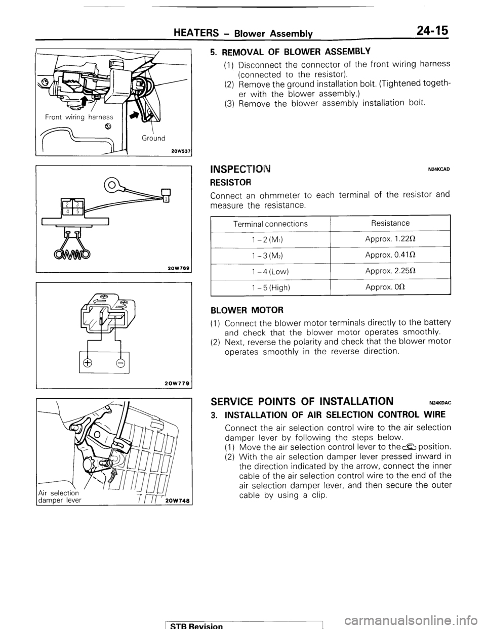
5. REMOVAL OF BLOWER ASSEMBLY (1) Disconnect the connector of the front wiring harness
(connected to the resistor).
(2) Remove the ground installation bolt. (Tightened togeth-
er with the blower assembly.)
(3) Remove the blower assembly installation bolt.
INSPECT00 N24KCAD
RESISTOR Connect an ohmmeter to each terminal of the resistor and
measure the resistance.
Terminal connections
1 -2(M1)
1 -3(M2) I-4(Low)
1 - 5 (High)
BLOWER MOTOR Resistance
Approx. 1.22R
Approx. 0.41 R
Approx. 2.25112
Approx. OlR
(1) Connect the blower motor terminals directly to the battery
and check that the blower motor operates smoothly.
(2) Next, reverse the polarity and check that the blower motor
operates smoothly in the reverse direction.
SERVICE POINTS OF INSTALLATION N24KDAC
3. INSTALLATION OF AIR SELECTION CONTROL WIRE Connect the air selection control wire to the air selection
damper lever by following the steps below.
(1) Move the air selection control lever to the& position.
(2) With the air selection damper lever pressed inward in
the direction indicated by the arrow, connect the inner
cable of the air selection control wire to the end of the
air selection damper lever, and then secure the outer
cable by using a clip.
1 STB Revision