ECU MITSUBISHI MONTERO 1987 1.G Workshop Manual
[x] Cancel search | Manufacturer: MITSUBISHI, Model Year: 1987, Model line: MONTERO, Model: MITSUBISHI MONTERO 1987 1.GPages: 284, PDF Size: 14.74 MB
Page 2 of 284
2 INTRODUCTION - How To Use This Manual
HOW TO USE THIS MANUAL NOOBAAK
CONTENTS
The preceding page contains the GROUP INDEX
which lists the group title and group number.
PAGE NUMBERS
All page numbers consist of two sets of digits
separated by a dash. The digits preceding the dash
identify the number of the group. The digits follow-
ing the dash represent the consecutive page
number within the group. The page numbers can
be found on the top left or right of each page.
TEXT
Unless otherwise specified, each service procedure
covers all models. Procedures covering specific
models are identified by the model codes, or similar
designation (engine type, transmission type, etc.).
A description of these designations is covered in
this unit under “VEHICLE IDENTIFICATION”.
SERVICE PROCEDURES
The service steps are arranged in numerical order
and attentions to be paid in performing vehicle ser-
vice are described in detail in SERVICE POINTS.
DEFINITION OF TERMS
STANDARD VALUE
Indicates the value used as the standard for judging
the quality of a part or assembly on inspection or the
value to which the part or assembly is corrected and
adjusted. It is given by tolerance.
LIMIT
Shows the standard for judging the quality of a part
or assembly on inspection and means the maximum
or minimum value within which the part or assembly
must be kept functionally or in strength. It is a value
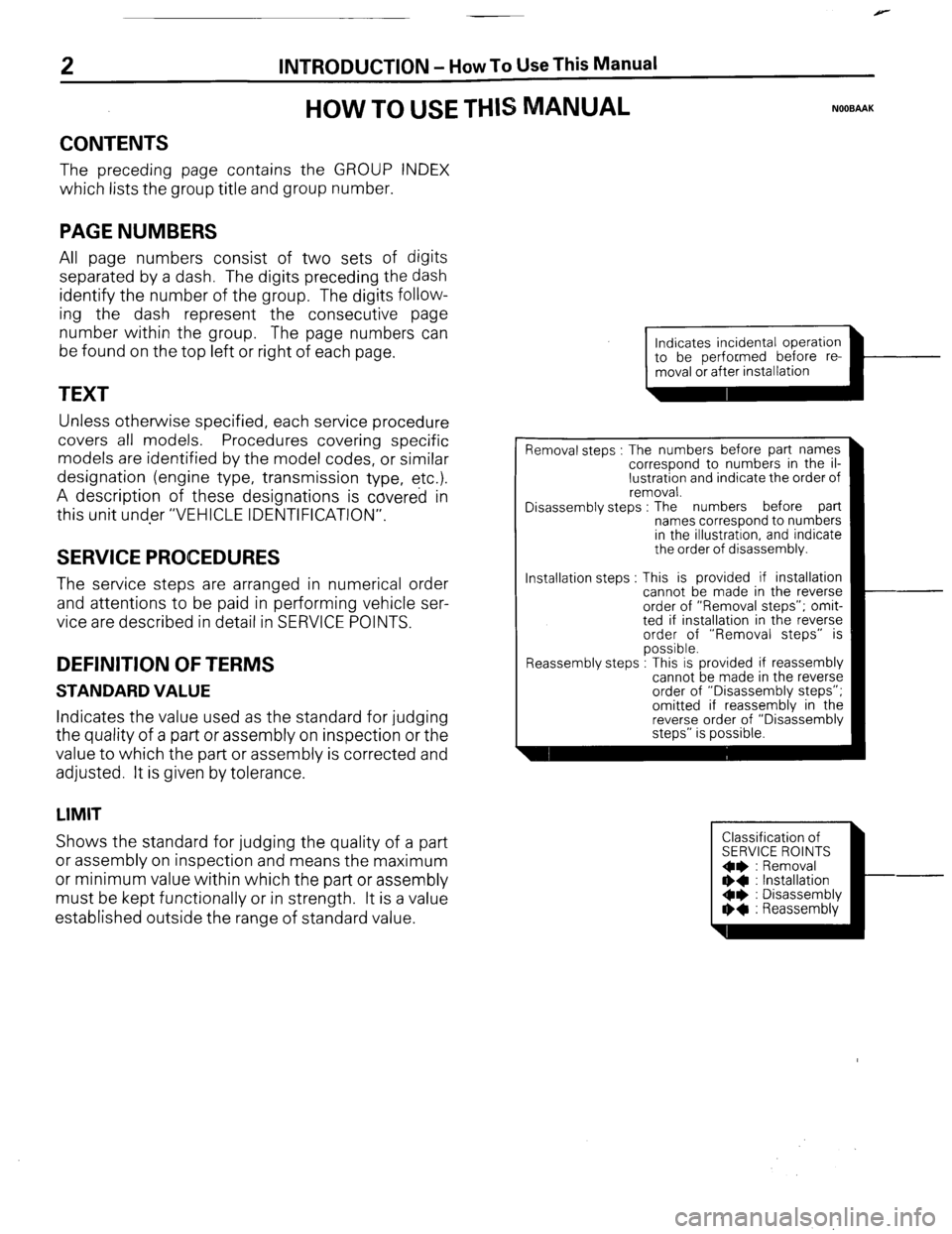
established outside the range of standard value. Installation steps
Indicates incidental operation
piiiKL=l-
Removal steps : The numbers before part names
correspond to numbers in the il-
lustration and indicate the order of
removal.
Disassembly steps : The numbers before part
names correspond to numbers
in the illustration, and indicate
the order of disassembly.
This is provided if installation
cannot be made in the reverse
order of “Removal steps”; omit-
ted if installation in the reverse
order of “Removal steps” is
possible.
.
Reassembly steps : I his IS provided It reassembly
cannot be made in the reverse
order of “Disassembly steps”;
omitted if reassembly in the
reverse order of “Disassembly
steps” is possible.
Classification of
SERVICE ROINTS
Oe : Removal
** : Installation
Oe : Disassembly
I)+ : Reassembly
Page 9 of 284
INTRODUCTION - Precautions Before Service 9
nm (in.)
so0059
PARTS
When replacing parts, use MITSUBISHI genuine parts.
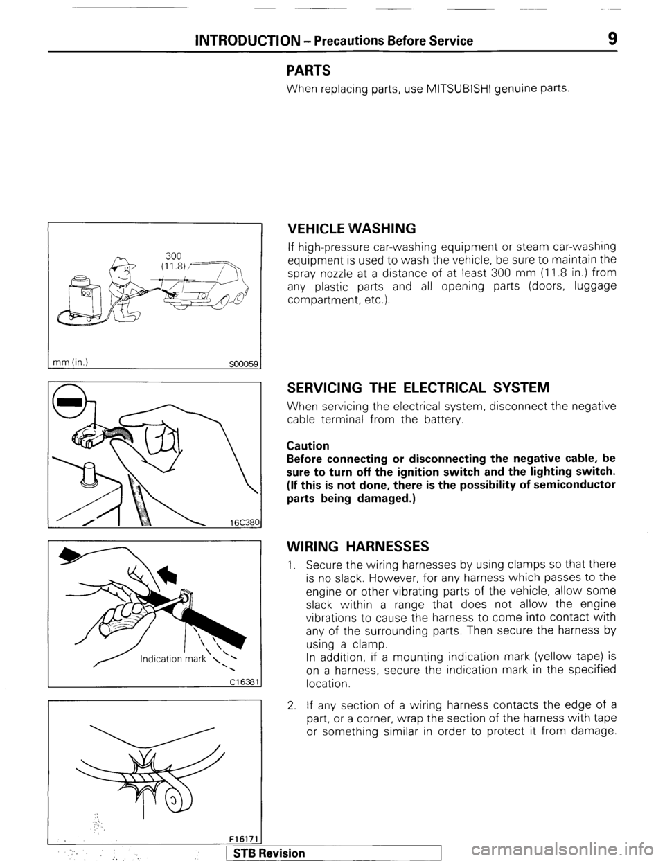
VEHICLE WVASHING
If high-pressure car-washing equipment or steam car-washing
equipment is used to wash the vehicle, be sure to maintain the
spray nozzle at a distance of at least 300 mm (1 1.8 in.) from
any plastic parts and all opening parts (doors, luggage
compartment, etc.).
SERVICING THE ELECTRICAL SYSTEM
When servicing the electrical system, disconnect the negative
cable terminal from the battery.
Caution
Before connecting or disconnecting the negative cable, be
sure to turn off the ignition switch and the lighting switch.
(If this is not done, there is the possibility of semiconductor
parts being damaged.)
WIRING HARNESSES
1. Secure the wiring harnesses by using clamps so that there
is no slack. However, for any harness which passes to the
engine or other vibrating parts of the vehicle, allow some
slack within a range that does not allow the engine
vibrations to cause the harness to come into contact with
any of the surrounding parts. Then secure the harness by
using a clamp.
In addition, if a mounting indication mark (yellow tape) is
on a harness, secure the indication mark in the specified
location.
2. If any section of a wiring harness contacts the edge of a
part, or a corner, wrap the section of the harness with tape
or something similar in order to protect it from damage.
F161711
* :, :, 1 STB Revision
Page 12 of 284
12 INTRODUCTION - Precautions Before Service
(3) If an ammeter or similar instrument is to be connected
to a live-wire circuit, use tape to protect the wire, use a
i clamp to secure the wire, and make sure that there is
, no contact with any other parts.
(4’) Be sure to provide a fuse for the load circuit of the
optional equipment.
FooO281
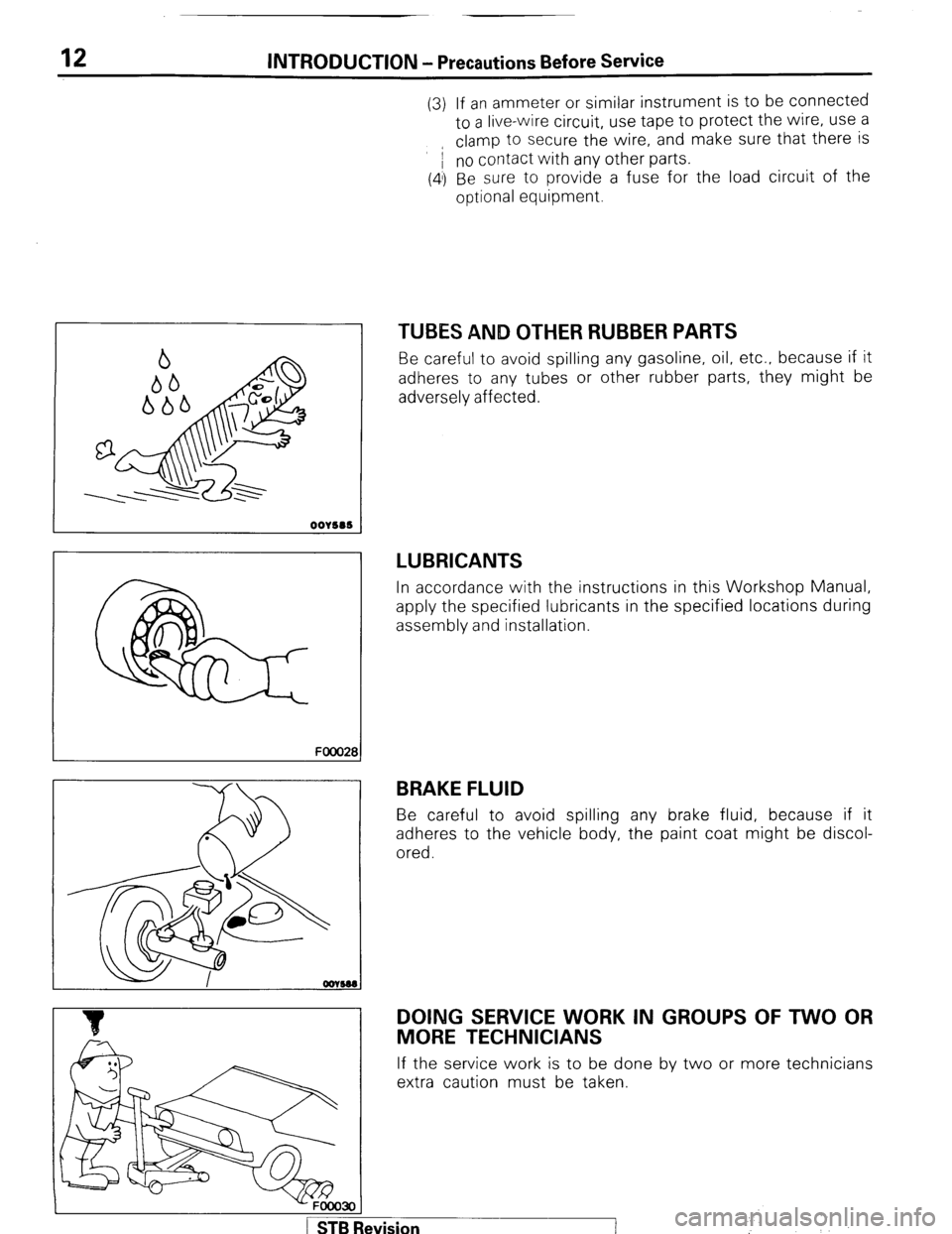
TUBES AND OTHER RUBBER PARTS
Be careful to avoid spilling any gasoline, oil, etc.. because if it
adheres to any tubes or other rubber parts, they might be
adversely affected.
LUBRICANTS
In accordance with the instructions in this Workshop Manual,
apply the specified lubricants in the specified locations during
assembly and installation.
BRAKE FLUID
Be careful to avoid spilling any brake fluid, because if it
adheres to the vehicle body, the paint coat might be discol-
ored.
DOING SERVICE WORK IN GROUPS OF TWO OR
MORE TECHNICIANS
If the service work is to be done by two or more technicians
extra caution must be taken.
-FOOO3OI
1 STB Revision ’
:
Page 14 of 284
INTRODUCTION - Towing and Hoisting
TOWING AND HOISTING NOOGA-
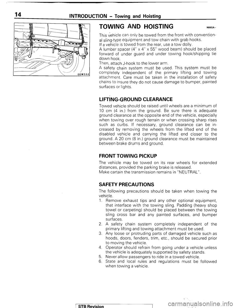
This vehicle can only be towed from the front with convention-
al sling-type equipment and tow chain with grab hooks.
If a vehicle is towed from the rear, use a tow dolly.
A lumber spacer (4” x 4” x 55” wood beam) should be placed
forward of under guard and under towing hook/shipping tie
down hook.
Then, attach J-hook to the lower arm.
A safety chain system must be used. This system must be
completely independent of the primary lifting and towing
attachment. Care must be taken in the installation of safety
chains to insure they do not cause damage to bumper, painted
surfaces or lights.
LIFT!NG-GROUND CLEARANCE
Towed vehicle should be raised until wheels are a minimum of
10 cm (4 in.) from the ground. Be sure there is adequate
ground clearance at the opposite end of the vehicle, especially
when towing over rough terrain or when crossing sharp rises
such as curbs. If necessary, ground clearance can be in-
creased by removing the wheels from the lifted end of the
disabled vehicle and carrying the lifted end closer to the
ground. A 20 cm (8 in.) ground clearance must be maintained
between brake drums and ground.
FRONT TOWING PICKUP
The vehicle may be towed on its rear wheels for extended
distances, provided the parking brake is released.
Make cartain the transmission remains in “NEUTRAL”.
SAFETY PRECAUTIONS
The following precautions should be taken when towing the
vehicle.
1. Remove exhaust tips and any other optional equipment,
that interface with the towing sling. Padding (heavy shop
towel or carpeting) should be placed between the towing
sling cross bar and any painted surfaces, and bumper
surfaces.
2. A safety chain system completely independent of the
primary lifting and towing attachment must be used.
3. Any loose or protruding parts of damaged vehicle such as
hoods, doors, fenders, trim, etc., should be secured prior
to moving the vehicle.
4. Operator should refrain from going under a vehicle unless
the vehicle is adequately supported by safety stands.
5. Never allow passengers to ride in a towed vehicle.
6. State and local rules and regulations must be followed
when towing a vehicle.
1 STB Revision
‘
Page 29 of 284
INSPECTION OF HARNESS CONNECTOR - Inspection of Harness Connector 8-9
Connect to
harness
16UO500
16R1317
8; 4 16R1319
INSPECTION OF HARNESS
CONNECTOR
NOECAM
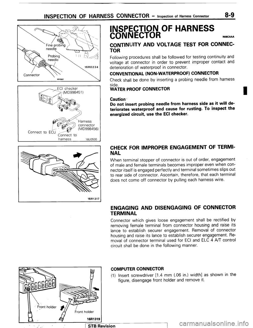
CONTINUITY AND VOLTAGE TEST FOR CONNEC-
TOR
Following procedures shall be followed for testing continuity and
voltage at connector in order to prevent improper contact and
deterioration of waterproof in connector.
CONVENTIONAL (NON-WATERPROOF) CONNECTOR
Check shall be done by inserting a probing needle from harness
side.
WATER PROOF CONNECTOR
Caution.
Do not insert probing needle from harness side as it will de-
teriorates waterproof and cause for rusting. To inspect the
energized circuit, use the ECI checker.
CHECK FOR IMPROPER ENGAGEMENT OF TERMI-
NAL
When terminal stopper of connector is out of order, engagement
of male and female terminals becomes improper even when con-
nector itself is engaged perfectly and terminal sometimes slips out
to rear side of connector. Ascertain, therefore, that each terminal
does not come off connector by pulling each harness wire.
ENGAGING AND DISENGAGING OF CONNECTOR
TERMINAL
Connector which gives loose engagement shall be rectified by
removing female terminal from connector housing and raise its
lance to establish securer engagement. Removal of connector
housing and raise its lance to establish securer engagement. Re-
moval of connector terminal used for ECI and ELC 4 ,4/l control
circuit shall be done in the following manner.
COMPUTER CONNECTOR
(1) Insert screwdriver [1.4 mm (06 in.) width] as shown in the
figure, disengage front holder and remove it.
:
j ’ . _. 1 STB Revision
Page 38 of 284
WIRING HARNESS - Troubleshooting
1660236
Power
supply
h
Fuse
ON
/----
/
/
Motor
1660239
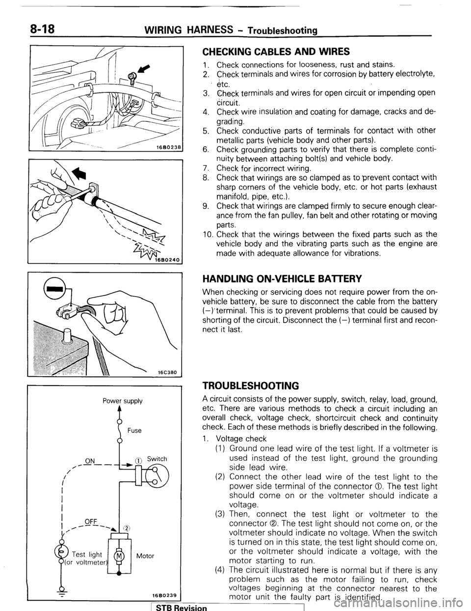
CHECKING CABLES AND WIRES
1. Check connections for looseness, rust and stains.
2. Check terminals and wires for corrosion by battery electrolyte,
$tc.
3. Check terminals and wires for open circuit or impending open
circuit.
4. Check wire insulation and coating for damage, cracks and de-
grading.
5. Check conductive parts of terminals for contact with other
metallic parts (vehicle body and other parts).
6. Check grounding parts to verify that there is complete conti-
nuity between attaching bolt(s) and vehicle body.
7. Check for incorrect wiring.
8. Check that wirings are so clamped as to ‘prevent contact with
sharp corners of the vehicle body, etc. or hot parts (exhaust
manifold, pipe, etc.).
9. Check that wirings are clamped firmly to secure enough clear-
ance from the fan pulley, fan belt and other rotating or moving
parts.
10. Check that the wirings between the fixed parts such as the
vehicle body and the vibrating parts such as the engine are
made with adequate allowance for vibrations.
HANDLING ON-VEHICLE BAlTERY
When checking or servicing does not require power from the on-
vehicle battery, be sure to disconnect the cable from the battery
(-)terminal. This is to prevent problems that could be caused by
shorting of the circuit. Disconnect the (-) terminal first and recon-
nect it last.
TROUBLESHOOTING
A circuit consists of the power supply, switch, relay, load, ground,
etc. There are various methods to check a circuit including an
overall check, voltage check, shortcircuit check and continuity
check. Each of these methods is briefly described in the following.
1. Voltage check
(1) Ground one lead wire of the test light. If a voltmeter is
used instead of the test light, ground the grounding
side lead wire.
(2) Connect the other lead wire of the test light to the
power side terminal of the connector 0. The test light
should come on or the voltmeter should indicate a
voltage.
(3) Then, connect the test light or voltmeter to the
connector (3,. The test light should not come on, or the
voltmeter should indicate no voltage. When the switch
is turned on in this state, the test light should come on,
or the voltmeter should indicate a voltage, with the
motor starting to run.
(4) The circuit illustrated here is normal but if there is any
problem such as the motor failing to run, check
voltages beginning at the connector nearest to the
motor unit the faulty part is identified. 1 ST6 Revision
Page 98 of 284
8-78 CHARGING SYSTEM - Service Adiustment Procedures
80A
n
Relay with diode
Voltmeter
Ammeter Iad
176
OUTPUT CURRENT TEST
This test judges whether or not the alternator gives an output
current that is equivalent to the nominal output.
Preparation
(1) Prior to the test, check the following items and correct as
necessary.
(a) Check the battery installed in the vehicle to ensure that it
is in sound state*. The battery checking method is de-
scribed in “BATTERY”.
NOTE
*The battery that is used to test the output current should
be one that has been rather discharged. With a fully
charged battery, the test may not be conducted correctly
due to an insufficient load.
(b) Check tension of the alternator drive belt. The belt tension
check method is described in “GROUP 7 COOLING -
Service Adjustment Procedures”.
(2) Turn off the ignition switch.
(3) Disconnect the battery ground cable.
(4) Disconnect the alternator output wire from the alternator “B”
terminal.
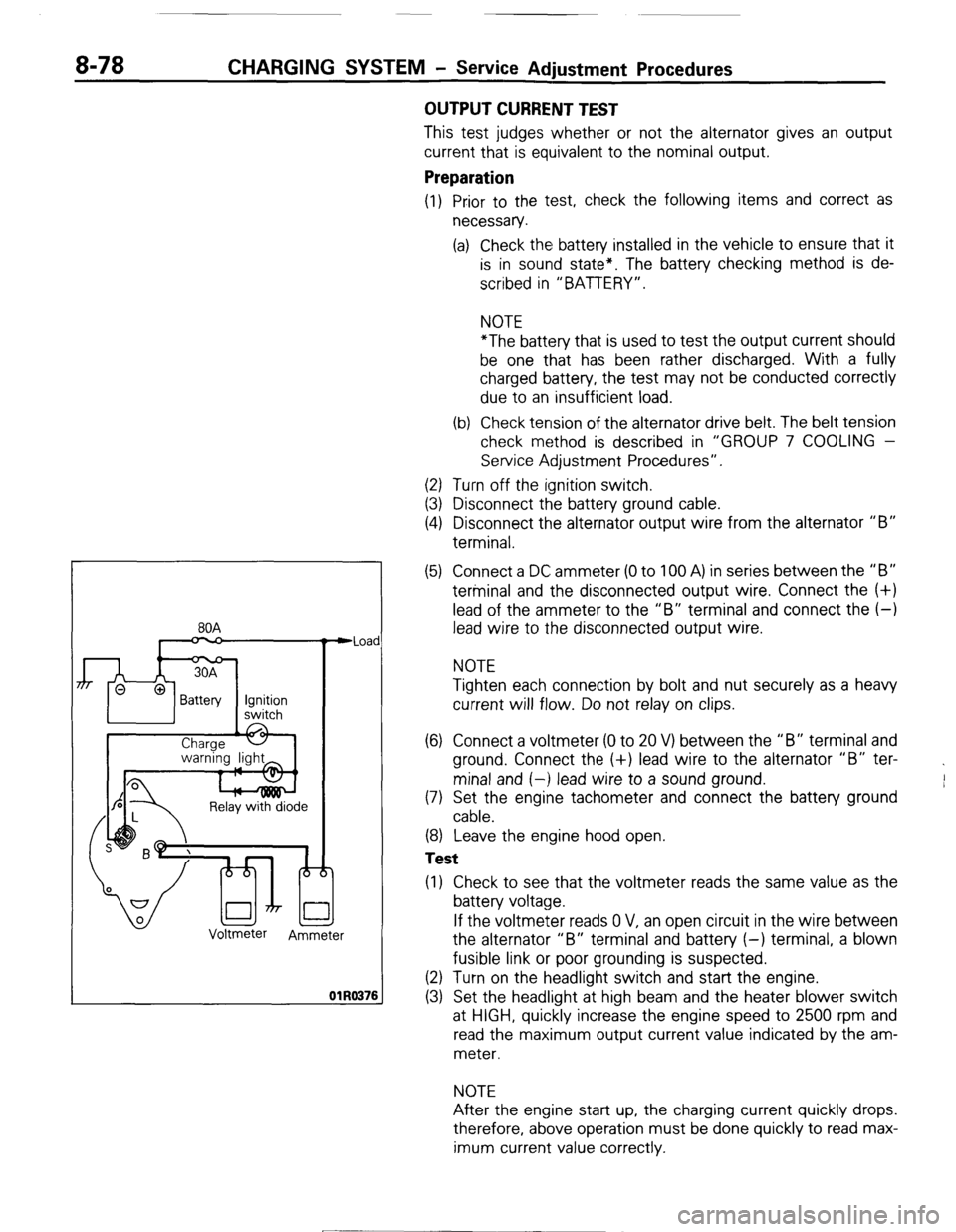
(5) Connect a DC ammeter (0 to 100 A) in series between the “B”
terminal and the disconnected output wire. Connect the (+)
lead of the ammeter to the “B” terminal and connect the (-)
lead wire to the disconnected output wire.
NOTE
Tighten each connection by bolt and nut securely as a heavy
current will flow. Do not relay on clips.
(6) Connect a voltmeter (0 to 20 V) between the “B” terminal and
ground. Connect the (+) lead wire to the alternator “B” ter-
minal and (-) lead wire to a sound ground.
(7) Set the engine tachometer and connect the battery ground
cable.
(8) Leave the engine hood open.
Test
(1) Check to see that the voltmeter reads the same value as the
battery voltage.
If the voltmeter reads 0 V, an open circuit in the wire between
the alternator “B” terminal and battery (-) terminal, a blown
fusible link or poor grounding is suspected.
(2) Turn on the headlight switch and start the engine.
(3) Set the headlight at high beam and the heater blower switch
at HIGH, quickly increase the engine speed to 2500 rpm and
read the maximum output current value indicated by the am-
meter.
NOTE
After the engine start up, the charging current quickly drops.
therefore, above operation must be done quickly to read max-
imum current value correctly.
[ STB Revision
--I
Page 101 of 284
CHARGING SYSTEM - Service Adjustment Procedures 8-81
(2) Upon completion of the test, set the engine speed at idle and
turn off the ignition switch.
(3) Disconnect the battery ground cable.
(4) Remove the test voltmeter and ammeter and the engine ta-
chometer.
(5) Connect the alternator output wire to the alternator “B” ter-
minal.
(6) Connect the battery ground cable.
ll3Y1848 2. Remove battery from vehicle.
Caution
White
I Blue
I Care should be taken in the event battery case is cracked
or leaking to protect hands from the electrolyte. A suit-
able pair of rubber gloves (not the household type) should
be worn when removing battery by hand.
3. Inspect battery carrier for damage caused by loss of acid from
battery. If acid damage is present, it will be necessary to clean
area with a solution of clean warm water and baking soda.
Scrub area with a stiff bristle brush and wipe off with a cloth
moistened with ammonia or baking soda in water.
4. Clean top of battery with same solutions as described in Step
(3).
INSPECTION OF BATTERY NOBEIBA
VISUAL INSPECTION OF BATTERY (1)
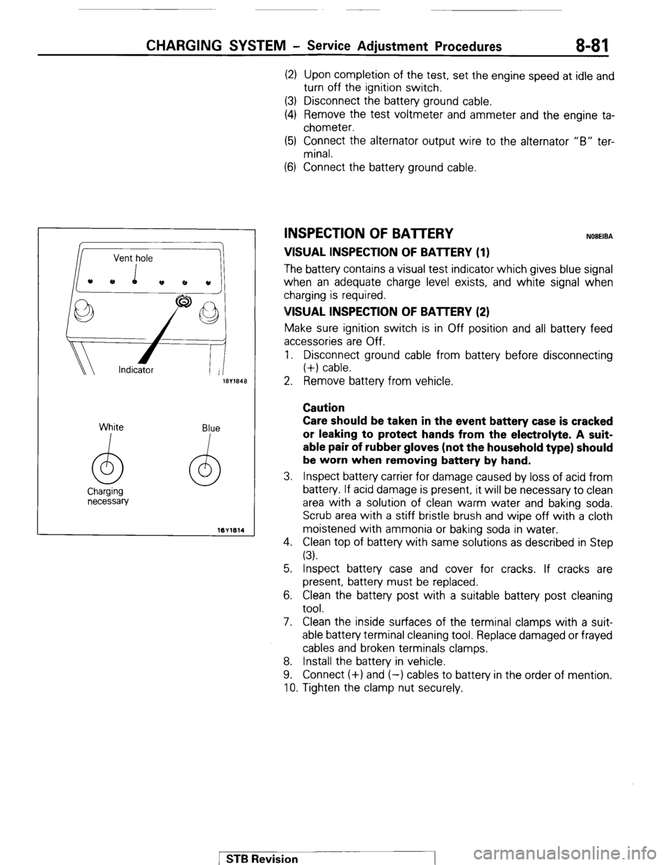
The batten/ contains a visual test indicator which gives blue signal
when an adequate charge level exists, and white signal when
charging is required.
VISUAL INSPECTION OF BAlTERY (2)
Make sure ignition switch is in Off position and all battery feed
accessories are Off.
1. Disconnect ground cable from battery before disconnecting
(+) cable.
5. Inspect battery case and cover for cracks. If cracks are
present, battery must be replaced.
6. Clean the battery post with a suitable battery post cleaning
tool.
7. Clean the inside surfaces of the terminal clamps with a suit-
able battery terminal cleaning tool. Replace damaged or frayed
cables and broken terminals clamps.
8. Install the battery in vehicle.
9. Connect (+) and (-) cables to battery in the order of mention.
10. Tighten the clamp nut securely.
1 STB Revision
Page 131 of 284
IGNITION SYSTEM - Service Adjustment Procedures 8-111
SERVICE ADJUSTMENT PROCEDURES
CHECKING IGNITION TIMING NOEGIBA
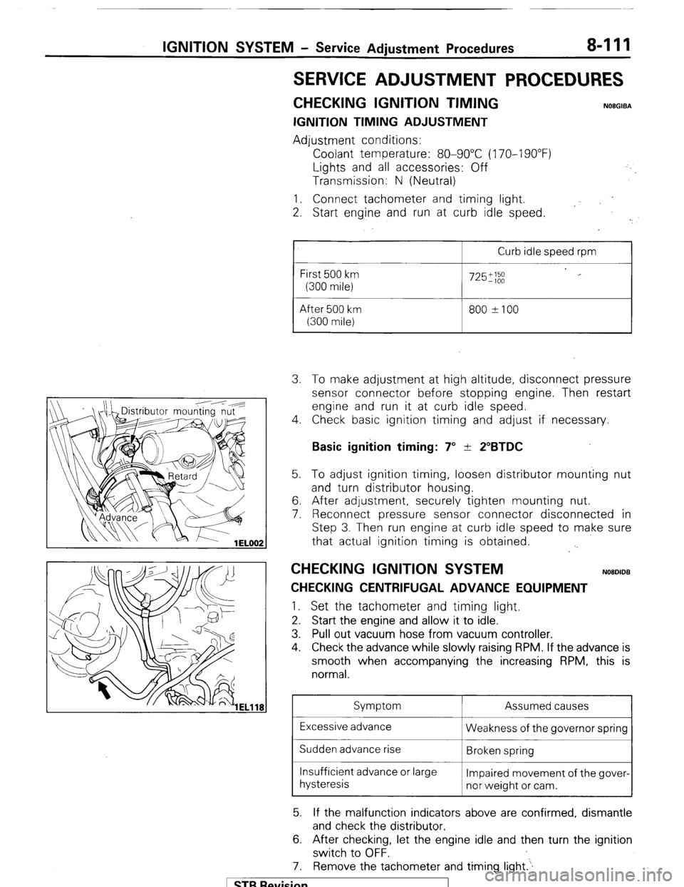
IGNITION TIMING ADJUSTMENT
Adjustment conditions:
Coolant temperature: 80-90°C (170-I 90°F)
Lights and all accessories: Off
Transmission: N (Neutral)
1. Connect tachometer and timing light.
2. Start eng.ine and run at curb idle speed.
I
Curb idle speed rpm
First 500 km
(300 mile)
After 500 km
(300 mile)
725';;;
800 ?I00 3. To make adjustment at high altitude, disconnect pressure
sensor connector before stopping engine. Then restart
engine and run it at curb idle speed.
4. Check basic ignition timing and adjust if necessary.
Basic ignition timing: 7” + 2”BTDC 5. To adjust ignition timing, loosen distributor mounting nut
and turn distributor housing.
6. After adjustment, securely tighten mounting nut.
7. Reconnect pressure sensor connector disconnected in
Step 3. Then run engine at curb idle speed to make sure
that actual ignition timing is obtained.
. .
CHECKING IGNITION SYSTEM NOBDIDB
CHECKING CENTRIFUGAL ADVANCE EQUIPMENT 1.
Set the tachometer and timing light.
2. Start the engine and allow it to idle.
3. Pull out vacuum hose from vacuum controller.
4. Check the advance while slowly raising RPM. If the advance is
smooth when accompanying the increasing RPM, this is
normal.
Symptom Assumed causes
Excessive advance
Weakness of the governor spring
Sudden advance rise
Broken spring
Insufficient advance or large
Impaired movement of the gover-
hysteresis
nor weight or cam.
5. If the malfunction indicators above are confirmed, dismantle
and check the distributor.
6. After checking, let the engine idle and then turn the ignition
switch to OFF.
7. Remove the tachometer and timing light.‘.
1 STB Revision
Page 137 of 284
IGNITION SYSTEM-Ignition System 8417
Notch on
crankshaft
pulley
Stud 2
SERVICE POINTS OF INSTALLATION
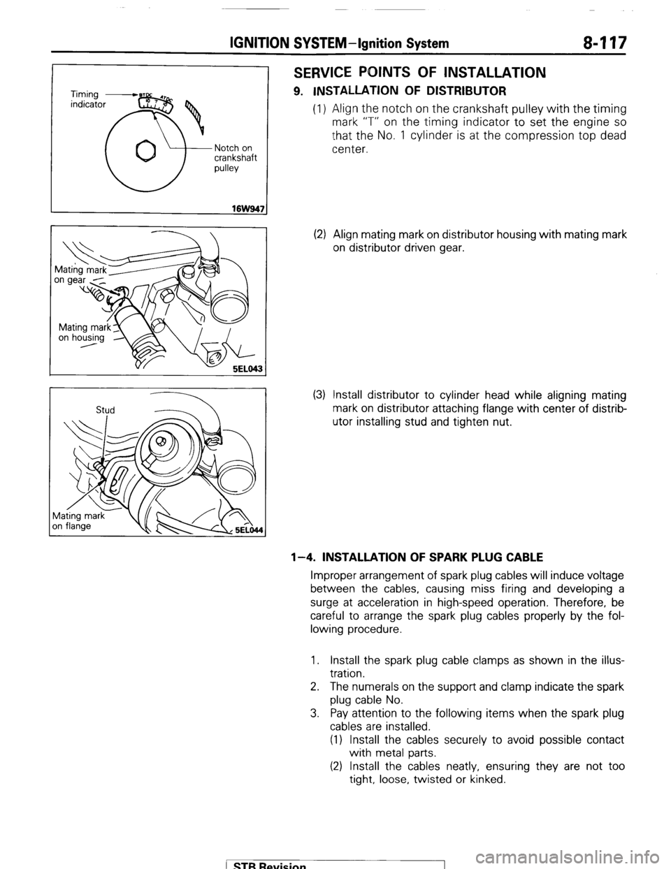
9. INSTALLATION OF DISTRIBUTOR
(1) Align the notch on the crankshaft pulley with the timing
mark “T” on the timing indicator to set the engine so
that the No. 1 cylinder is at the compression top dead
center.
(2) Align mating mark on distributor housing with mating mark
on distributor driven gear.
(3) Install distributor to cylinder head while aligning mating
mark on distributor attaching flange with center of distrib-
utor installing stud and tighten nut.
l-4. INSTALLATION OF SPARK PLUG CABLE
Improper arrangement of spark plug cables will induce voltage
between the cables, causing miss firing and developing a
surge at acceleration in high-speed operation. Therefore, be
careful to arrange the spark plug cables properly by the fol-
lowing procedure.
1. Install the spark plug cable clamps as shown in the illus-
tration.
2. The numerals on the support and clamp indicate the spark
plug cable No.
3. Pay attention to the following items when the spark plug
cables are installed.
(1) Install the cables securely to avoid possible contact
with metal parts.
(2) Install the cables neatly, ensuring they are not too
tight, loose, twisted or kinked.
( STB Revision