Ignition coil MITSUBISHI MONTERO 1987 1.G User Guide
[x] Cancel search | Manufacturer: MITSUBISHI, Model Year: 1987, Model line: MONTERO, Model: MITSUBISHI MONTERO 1987 1.GPages: 284, PDF Size: 14.74 MB
Page 133 of 284
IGNITION SYSTEM-Service Adjustment Procedures 8-113
SPARK TEST - ENGINE CANNOT BE CRANKED
If spark test is performed by cranking while the catalyst is hot,
unburned gas will be supplied to the catalyst, and this is not de-
sirable to the catalyst.
For this reason, use the following methods which allow spark test
to be performed without cranking.
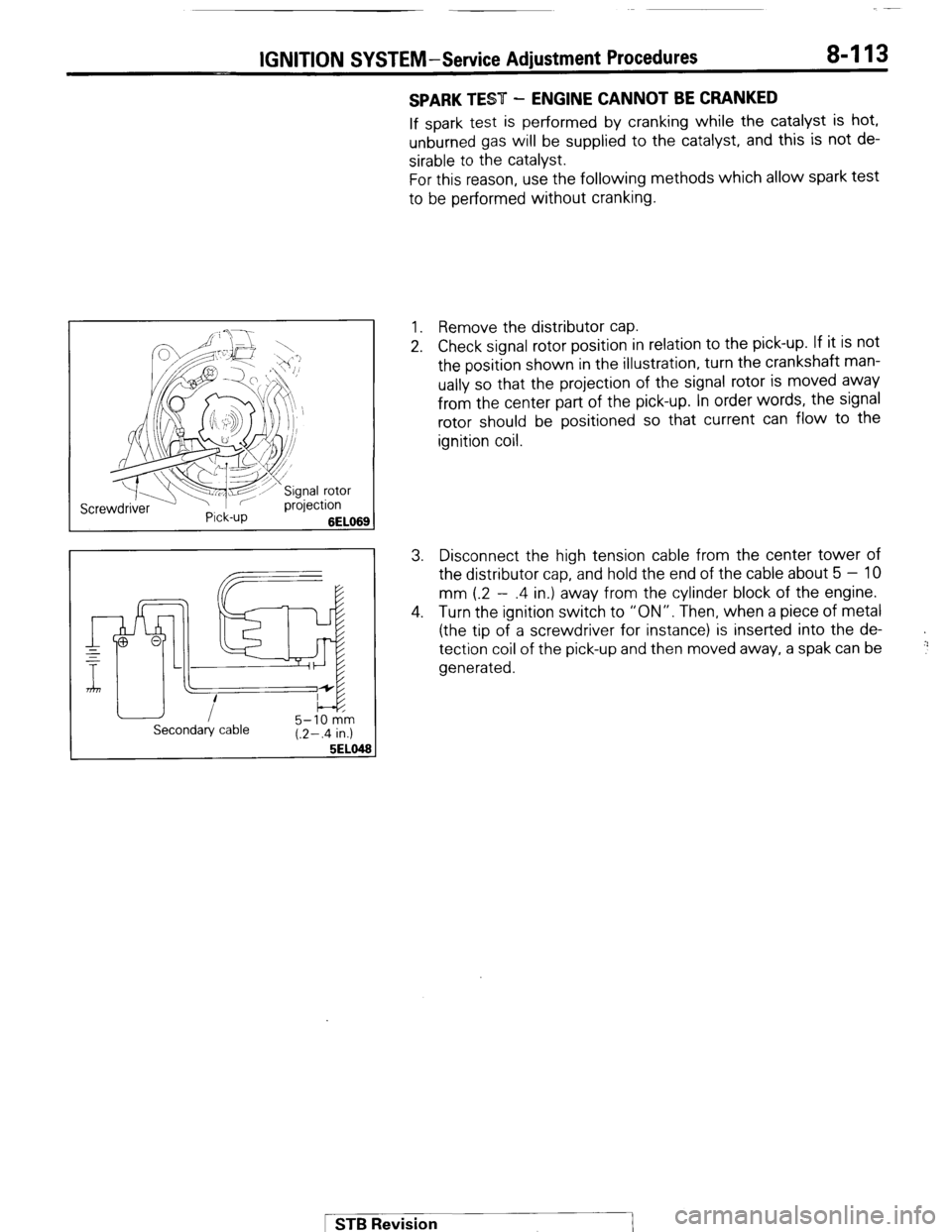
1. Remove the distributor cap.
2. Check signal rotor position in relation to the pick-up. If it is not
the position shown in the illustration, turn the crankshaft man-
ually so that the projection of the signal rotor is moved away
from the center part of the pick-up. In order words, the signal
rotor should be positioned so that current can flow to the
ignition coil.
3. Disconnect the high tension cable from the center tower of
the distributor cap, and hold the end of the cable about 5 - 10
mm (.2 - .4 in.) away from the cylinder block of the engine.
4. Turn the ignition switch to “ON”. Then, when a piece of metal
(the tip of a screwdriver for instance) is inserted into the de-
tection coil of the pick-up and then moved away, a spak can be
generated.
+
!:’
Secondary cable 5-10 km
(.2-.4 in.)
5EL0
1 STB Revision
Page 134 of 284
8-114 IGNITION SYSTEM - Ignition System
IGNITION SYSTEM
REMOVAL AND INSTALLATION NOEGJAE
20-30
Nm
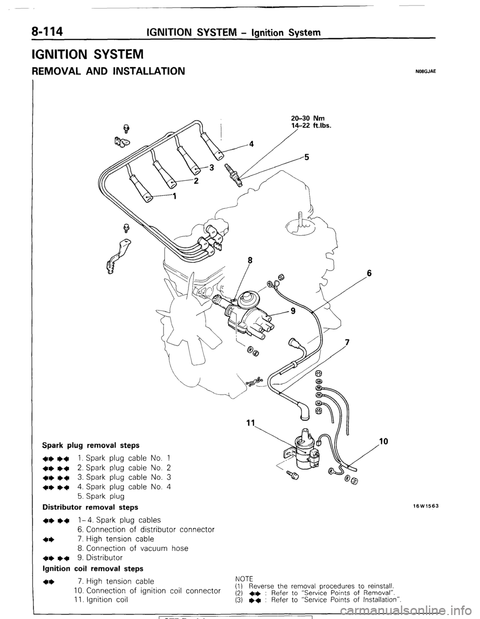
Spark plug removal steps
+e l
+ 1. Spark plug cable No. 1
~~ ~~ 2. Spark plug cable No. 2
+e e+ 3. Spark plug cable No. 3
*e e+ 4. Spark plug cable No. 4
5. Spark plug
Distributor removal steps
16W1563
~~ l + 1-4. Spark plug cables
6. Connection of distributor connector
+* 7. High tension cable
8. Connection of vacuum hose
de l
q 9. Distributor
Ignition coil removal steps
7. High tension cable NOTE
10. Connection of ignition coil connector (1) Reverse the removal procedures to reinstall.
(2) +e : Refer to “Service Points of Removal”. 11. Ignition coil (3) l + : Refer to “Service Points of Installation”
I
1 STB Revision
Page 136 of 284
8-116 IGNITION SYSTEM-Ignition System
Plug
cleaner
OlUOO89
Plug gap
gauge NIPPON
termine
rl
direction
High voltage
terminal
01R0234
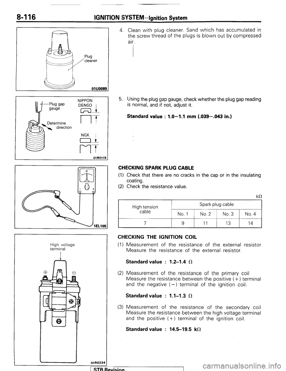
4. Clean with plug cleaner. Sand which has accumulated in
the screw thread of the plugs is blown out by compressed
air.
5. Using the plug gap gauge, check whether the plug gap reading
is normal, and if not, adjust it.
Standard value : 1.0-1.1 mm (.039-.043 in.)
CHECKING SPARK PLUG CABLE
(1) Check that there are no cracks in the cap or in the insulating
coating.
(2) Ctieck the resistance value.
High tension
cable Spark plug cable
No.1 1 No.2 1 No.3 1 No.4
I 9
I
11
I 13 I 14
CHECKING THE IGNITION COIL
(1) Measurement of the resistance of the external resistor
Measure the resistance of the external resistor. Standard value : 1.2-1.4 IR
(2) Measurement of the resistance of the primary coil
Measure the resistance between the positive (+) terminal
and the negative (-) terminal of the ignition coil. Standard value : 1.1-1.3 IR
(3) Measurement of the resistance of the secondary coil
Measure the resistance between the high voltage terminal
and the positive (+) terminal of the ignition coil. Standard value : 14.5-19.5 kfl
wision I
Page 143 of 284
METERS AND GAUGES-Specifications
METERS AND GAUGES
8-123
SPECIFICATIONS
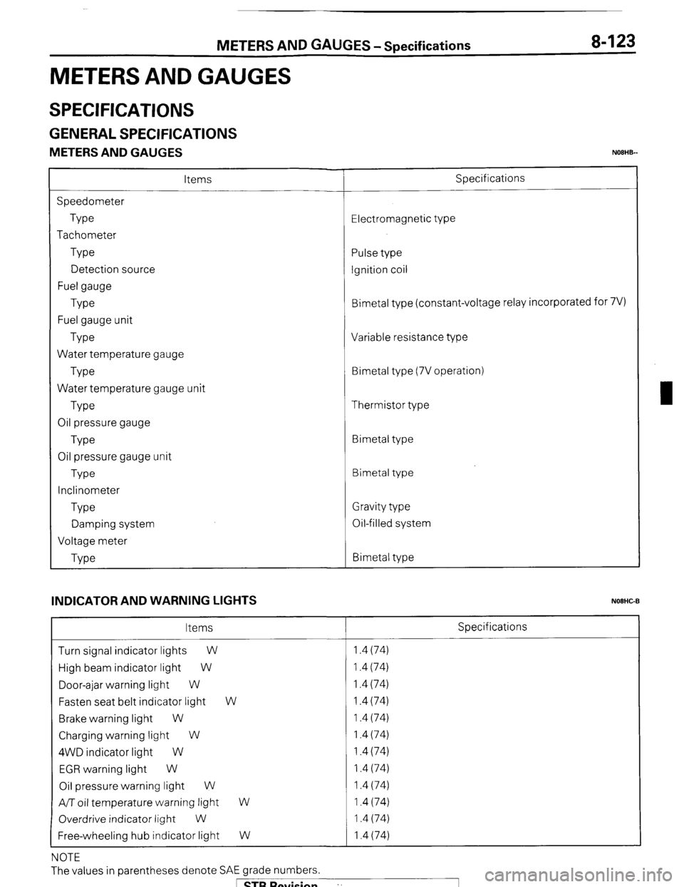
GENERAL SPECIFICATIONS
METERS AND GAUGES NOEHB-
Items
Speedometer
Type
Tachometer
Type
Detection source
Fuel gauge
Type
Fuel gauge unit
Type
Water temperature gauge
Type
Water temperature gauge unit
Type
Oil pressure gauge
Type
Oil pressure gauge unit
Type
Inclinometer
Type
Damping system
Voltage meter
Type Specifications
Electromagnetic type
Pulse type
Ignition coil
Bimetal type (constant-voltage relay incorporated for 7V)
Variable resistance type
Bimetal type (7V operation)
Thermistor type
Bimetal type
Bimetal type
Gravity type
Oil-filled system
Bimetal type
INDICATOR AND WARNING LIGHTS
NOEHC-B
Items Specifications
Turn signal indicator lights
W 1.4 (74)
High beam indicator light W 1.4 (74)
Door-ajar warning light W 1.4 (74)
Fasten seat belt indicator light W 1.4 (74)
Brake warning light W 1.4 (74)
Charging warning light W 1.4 (74)
4WD indicator light W 1.4 (74)
EGR warning light W 1.4 (74)
Oil pressure warning light W 1.4 (74)
A/T oil temperature warning light
W 1.4 (74)
Overdrive indicator light
W 1.4 (74)
Free-wheeling hub indicator light W 1.4 (74)
NOTE
The values in parentheses denote SAE grade numbers.
1 STB Revision ”
Page 231 of 284
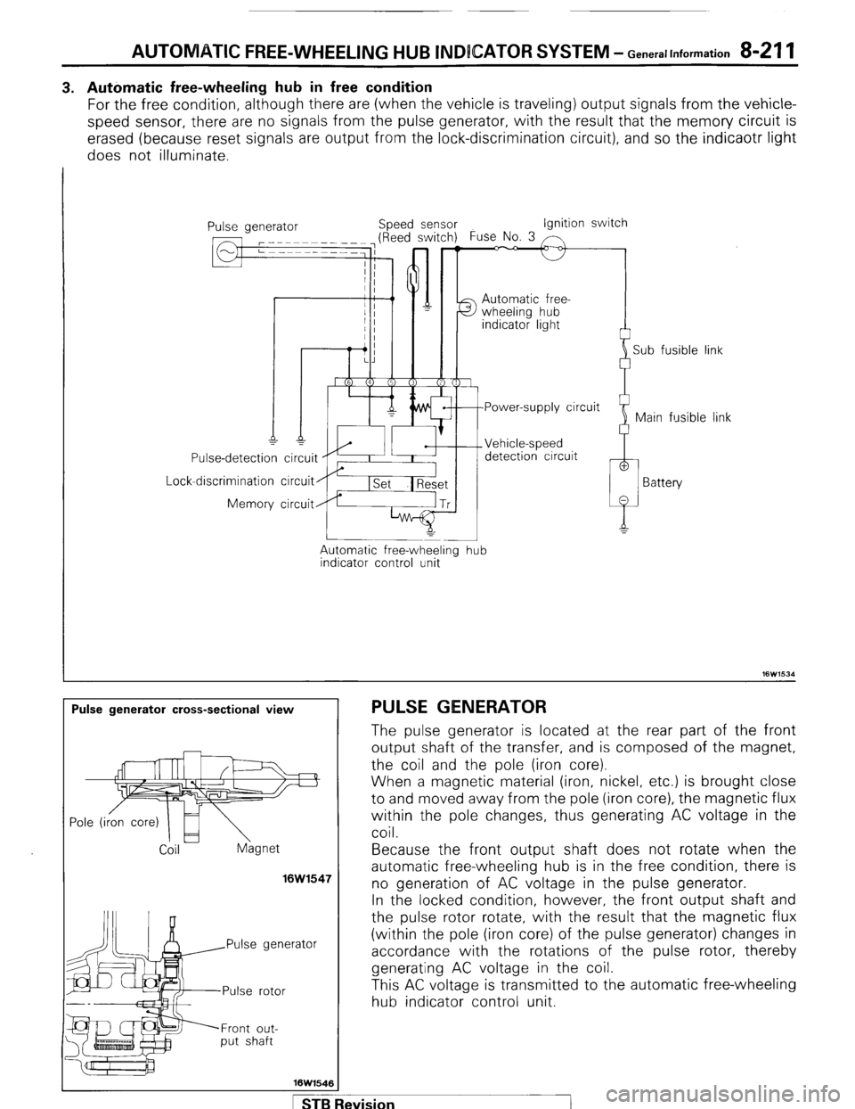
AUTOMATIC FREE-WHEELING HUB INDICATOR SYSTEM - Generallnformation 8-211
3. Automatic free-wheeling hub in free condition
For the free condition, although there are (when the vehicle is traveling) output signals from the vehicle-
speed sensor, there are no signals from the pulse generator, with the result that the memory circuit is
erased (because reset signals are output from the lock-discrimination circuit), and so the indicaotr light
does not illuminate.
I
Lock Use-detection
-discrimination
Memory ipeed sensor Ignition switch
Automatic free-
detection circuit
circuit
circuit
Automatic free-wheeling
indicator control unit -
hub i
Sub fusible link
link
Pulse generator cross-sectional view PULSE GENERATOR
Coil hgnet
16W1547
rator
Front out-
put shaft
16W1546 The pulse generator is located at the rear part of the front
output shaft of the transfer, and is composed of the magnet,
the coil and the pole (iron core).
When a magnetic material (iron, nickel, etc.) is brought close
to and moved away from the pole (iron core), the magnetic flux
within the pole changes, thus generating AC voltage in the
coil.
Because the front output shaft does not rotate when the
automatic free-wheeling hub is in the free condition, there is
no generation of AC voltage in the pulse generator.
In the locked condition, however, the front output shaft and
the pulse rotor rotate, with the result that the magnetic flux
(within the p o e I (’ Iron core) of the pulse generator) changes in
accordance with the rotations of the pulse rotor, thereby
generating AC voltage in the coil.
This AC voltage is transmitted to the automatic free-wheeling
hub indicator control unit.
STB Revision