Ignition coil MITSUBISHI MONTERO 1987 1.G Workshop Manual
[x] Cancel search | Manufacturer: MITSUBISHI, Model Year: 1987, Model line: MONTERO, Model: MITSUBISHI MONTERO 1987 1.GPages: 284, PDF Size: 14.74 MB
Page 49 of 284
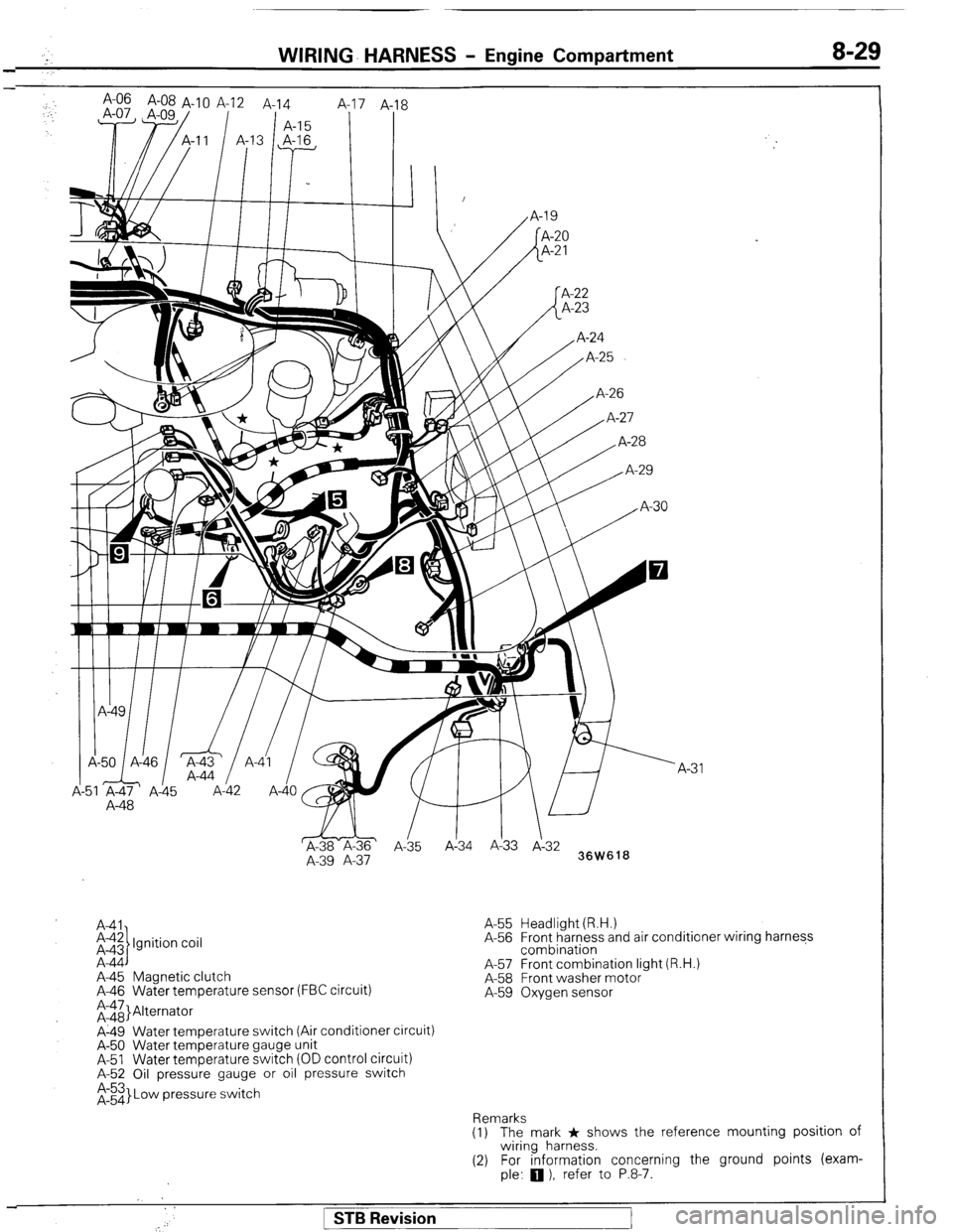
WIRING- HARNESS - Engine Compartment 8-29
; A-06 A-08 A-1 0 A-12 A-14
,.
1 A-15 8
I I
,I I I, I /
A-48
WI
&-ii& ’
A-35 Ai34 A!33 J-3:
A-39 A-37
36W618
A41
i-$ Ignition coil
A-44
A-45 Magnetic clutch
A-46 Water temperature sensor (FBC circuit)
;rii}Alternator
A-49 Water temperature switch (Air conditioner circuit)
A-50 Water temperature gauge unit
A-51 Water temperature switch (OD control circuit)
A-52 Oil pressure gauge or oil pressure switch
$3 Low pressure switch A-55 Headlight (R.H.)
A-56 Front harness and air conditioner wiring harness
combination
A-57 Front combination light (R.H.)
A-58 Front washer motor
A-59 Oxygen sensor
Remarks
(1) The mark * shows the reference mounting position of
wiring harness.
(2) For information concerning the ground points (exam-
ple:
q ), refer to P.8-7.
1 STB Revision
Page 59 of 284
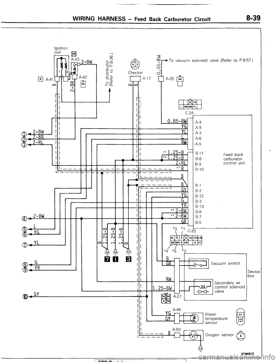
WIRING HARNESS - Feed Back Carburetor Circuit 8-39
Ignition
coil
) _ ,E3
$-To vacuum solenoid valve [Refer to P.8-57.1
7 A-42
cl BR
q A-4
c-2
, 0.85-BW
I YG
I ;
I : YL.
I
I ;
RW,
I :
‘A
f
r
A-4
A-9
A-3
A-6
A-5
B-l 1
B-6
B-9
B-IO Feed back
carburetor
control unit
I
II
II
(I I
1 I ! ! I I- - - - -. -_ __ __
L---- __._._
I +L----J I i-----,
B
B-l
B-2
B-l 2
B-3
B-13
B-8
B-7
B-5
A-46 Vacuum switch
Device
box
control solenoid
L
L
Water
temperature
sensor 1 STB Revision
Page 60 of 284
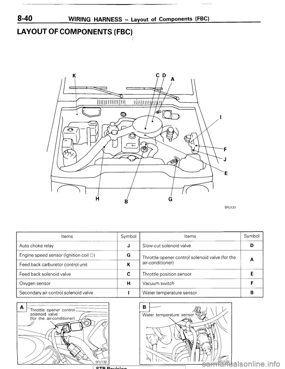
8-40 WIRING HARNESS - Layout of Components WC)
LAYOUT OFCOMPONENJS [FBC)
CD
II A
5FU131
Items
Symbol Items Symbol
Auto choke relay J Slow-cut solenoid valve D
Engine speed sensor (Ignition coil 0)
Feed back carburetor control unit G
Throttle opener control solenoid valve (for the
A
K air-conditioner)
Feed back solenoid valve
I
C Throttle position sensor
I E
Oxygen sensor
I H Vacuum switch
I F
Secondary air control solenoid valve
I I 1 Water temperature sensor
I B
Throttle opener contr
solenoid valve
Page 111 of 284
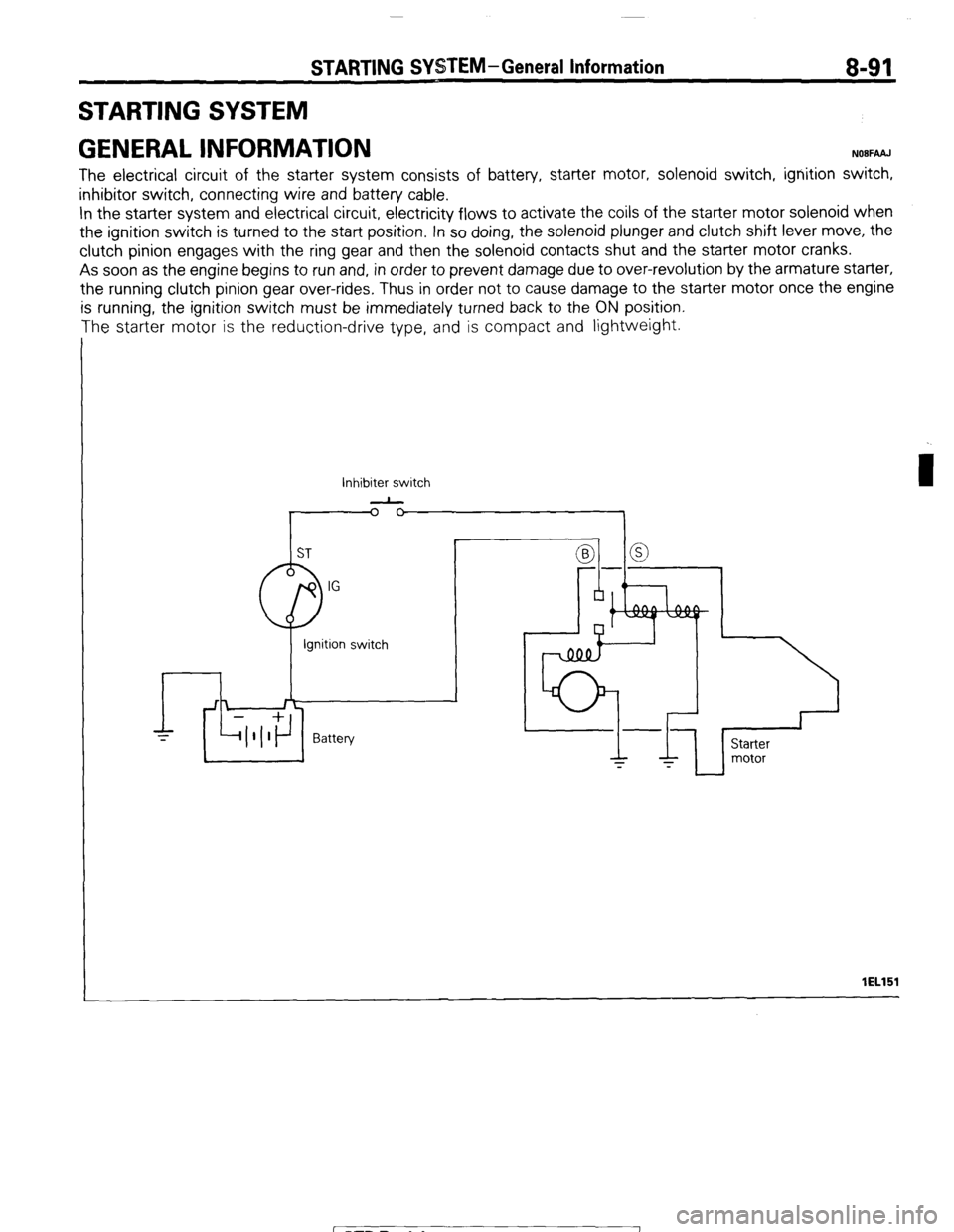
STARTING SYSTEM-General Information 8-91
STARTING SYSTEM
GENERAL INFORMATION
NOBFAAJ
The electrical circuit of the starter system consists of battery, starter motor, solenoid switch, ignition switch,
inhibitor switch, connecting wire and battery cable.
In the starter system and electrical circuit, electricity flows to activate the coils of the starter motor solenoid when
the ignition switch is turned to the start position. In so doing, the solenoid plunger and clutch shift lever move, the
clutch pinion engages with the ring gear and then the solenoid contacts shut and the starter motor cranks.
As soon as the engine begins to run and, in order to prevent damage due to over-revolution by the armature starter,
the running clutch pinion gear over-rides, Thus in order not to cause damage to the starter motor once the engine
is running, the ignition switch must be immediately turned back to the ON position.
The starter motor is the reduction-drive type, and is compact and lightweight.
Inhibiter switch
-
I lEL151
1 STB Revision
Page 125 of 284
IGNITION SYSTEM -General Information 8-105
IGNITION SYSTEM
GENERAL INFORMATION
NOUGAAB
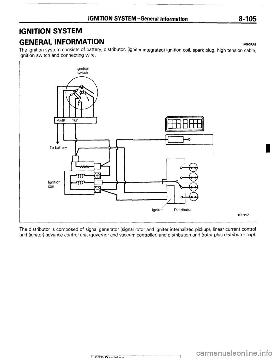
The ignition system consists of battery, distributor, (igniter-integrated) ignition coil, spark plug, high tension cable,
ignition switch and connecting wire.
Ignition
switch
0
m
I
1 AMR 1Gl
I
Ignition
coil
r
Ignite; Distributor
lEL117
The distributor is composed of signal generator (signal rotor and igniter internalized pickup), linear current control
unit (igniter) advance control unit (governor and vacuum controller) and distribution unit (rotor plus distributor cap).
Page 126 of 284
IGNITION SYSTEM-General Information
IISTRIBUTOR
Vacuum controller
lEL153
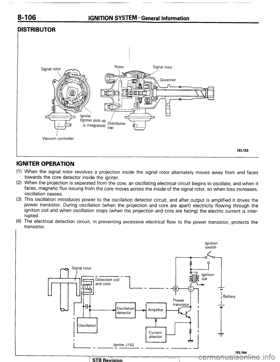
IGNITER OPERATION
(1) When the signal rotor revolves a projection inside the signal rotor alternately moves away from and faces
towards the core detector inside the igniter.
(2) When the projection is separated from the core, an oscillating electrical circuit begins to oscillate, and when it
faces, magnetic flux issuing from the core moves across the inside of the signal rotor, so when loss increases,
oscillation ceases.
(3) This oscillation introduces power to the oscillation detector circuit, and after output is amplified it drives the
power transistor. During oscillation (when the projection and core are apart) electricity flowing through the
ignition coil and when oscillation stops (when the projection and core are facing) the electric current is inter-
rupted.
(4) The electrical detection circuit, in preventing excessive electrical flow to the power transistor, protects the
transistor.
Ignition
switch
m Sig,nal rotor
Detection coil
and core -I- ----
Power
Oscillation - Amplifier
detector
Oscillation
Current
ditector
Igniter J152
-.I-
T
1 Battery
I
-
T
1 STB Revision
-7
Page 127 of 284
IGNITION SYSTEM - Specifications 8-107
SPECIFICATIONS
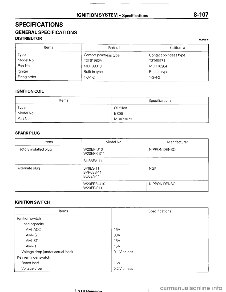
GENERAL SPECIFICATIONS
DISTRIBUTOR N08GB.B
Type
Model No.
Part No.
Igniter
Firing order Items Federal
Contact pointless type
T3T61980A
MD109013
Built-in type
1-3-4-2 California
Contact pointless type
T3T65571
MD1 10264
Built-in type
1-3-4-2
IGNITION COIL
Type
Model No.
Part No. Items
Oil filled
E-089
M DO73079 Specifications
SPARK PLUG
Items
Factory installed plug Model No. Manifacturer
W20EP-U 10 NIPPON DENS0
W20EPR-Sll
BURGEA-1 1
Alternate plug BPGES-1 1
BPRGES-1 1
BUGEA-11 NGK
W20EPR-U IO
W20EPSll NIPPON DENS0
IGNITION SWITCH
Items
ignition switch
Load capacity
AM-ACC
AM-IG
AM-ST
AM-R
Voltage drop (under actual load)
Key reminder switch
Rated load
Voltage drop Specifications
15A
30A
15A
15A
0.1 V or less
IW
0.2 V or less
) STB Revision
Page 128 of 284
8408 IGNITION SYSTEM - Specifications
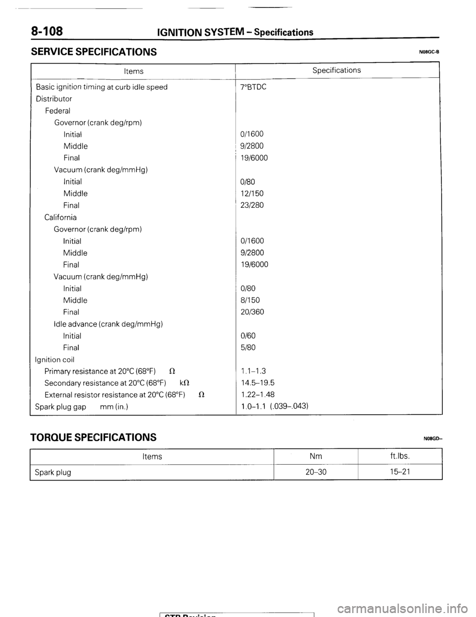
SERVICE SPECIFICATIONS
N08GC-B
Items Specifications
Basic ignition timing at curb idle speed 7”BTDC
Distributor
Federal
Governor (crank deghpm)
Initial O/l 600
Middle 1 9/2800
Final 1 g/6000
Vacuum (crank deg/mmHg)
Initial
O/80
Middle 12/I 50
Final 231280
California
Governor (crank deghpm)
initial O/l 600
Middle 912800
Final 1 g/6000
Vacuum (crank deg/mmHg)
Initial O/80
Middle 8/l 50
Final 201360
Idle advance (crank deg/mmHg)
Initial O/60
Final 5180
Ignition coil
Primary resistance at 20°C (68°F) R 1.1-1.3
Secondary resistance at 20°C (68°F) k0 14.5-19.5
External resistor resistance at 20°C (68°F) 1R 1.22-1.48
Spark plug gap mm (in.) 1.0-I .I (.039-,043)
TORQUE SPECIFICATIONS
Items Nm
NOBGD-
ft.lbs.
Spark plug 20-30 15-21
1 STB Revision
Page 129 of 284
IGNITLON SYSTEM -Troubleshooting 8-109
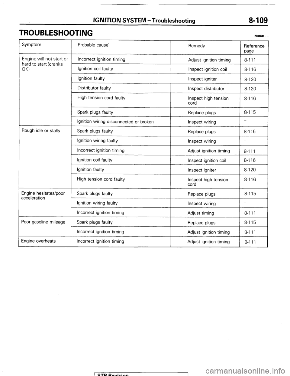
TROUBLESHOOTING
NOBGH--
Symptom Probable cause
Remedy
Reference
paw
Engine will not start or
Incorrect ignition timing
8-111
hard to start (cranks Adjust ignition timing
OKI Ignition coil faulty
Inspect ignition coil 8-116
Ignition faulty
Inspect igniter
8-120
Distributor faulty
Inspect distributor 8-120
High tension cord faulty
Inspect high tension 8-116
cord
Spark plugs faulty Replace plugs 8-115
Ignition wiring disconnected or broken
Inspect wiring -
Rough idle or stalls
Spark plugs faulty
Replace plugs 8-115
Ignition wiring faulty
Inspect wiring -
Incorrect ignition timing
Adjust ignition timing
8-111
Ignition coil faulty
Inspect ignition coil 8-116
Ignition faulty
Inspect igniter 8-120
High tension cord faulty
Inspect high tension 8-116
cord
Engine hesitates/poor
acceleration Spark plugs faulty Replace plugs 8-115
Ignition wiring faulty
Inspect wiring -
Incorrect ignition timing
Adjust timing 8-111
Poor gasoline mileage
Spark plugs faulty Replace plugs 8-115
Incorrect ignition timing Adjust ignition timing 8-111
Engine overheats Incorrect ignition timing
Adjust ignition timing
8-111 1 STB Revision
Page 130 of 284
8-110 IGNITION SYSTEM - Circuit Diagram
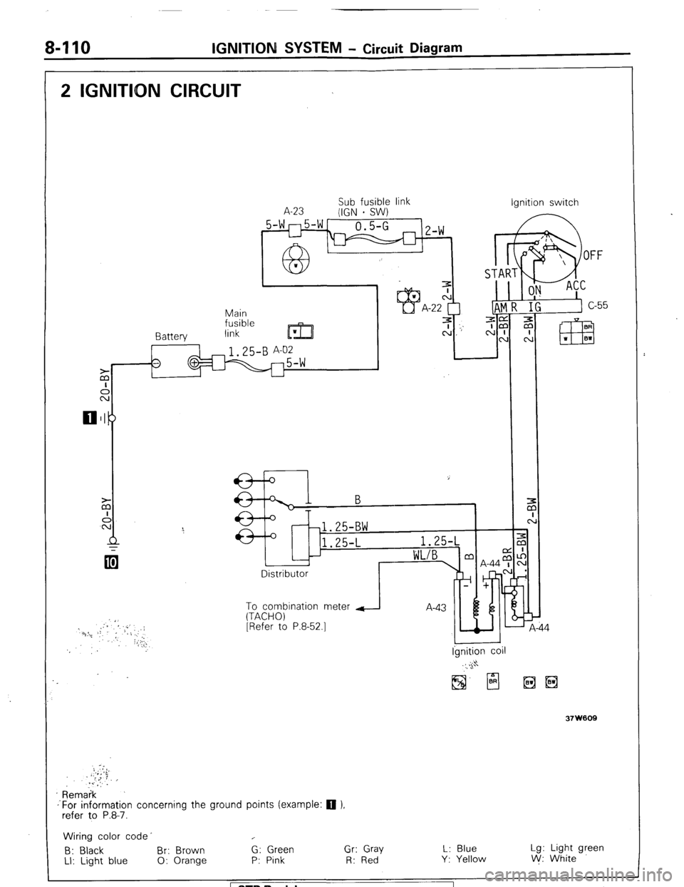
2 IGNITDN CIRCUIT
Sub fusible link
A-23
(IGN - SW) Ignition switch
5-wn5-w-
0.5-G 1
u
63- Z-W
I
IAT
Main 1
fusible
Rnttprv link
m
ze 3 cj _-’ A:“p m
N CL
I 64-b I I I m
I
Ei
I
L Disi
To combination meter d A-an b
(TACHO)
[Refer to P.8-52.1
I I Ignition coil
37 w009
Remaik
-‘For information concerning the ground points (example: q ),
refer to P.8-7.
Wiring color code’ c
B: Black Br: Brown G: Green Gr: Gray L: Blue Lg: Light green
LI: Light blue 0: Orange P: Pink R: Red Y: Yellow V/: White
1 STB Revision 1