relay MITSUBISHI MONTERO 1987 1.G User Guide
[x] Cancel search | Manufacturer: MITSUBISHI, Model Year: 1987, Model line: MONTERO, Model: MITSUBISHI MONTERO 1987 1.GPages: 284, PDF Size: 14.74 MB
Page 38 of 284
WIRING HARNESS - Troubleshooting
1660236
Power
supply
h
Fuse
ON
/----
/
/
Motor
1660239
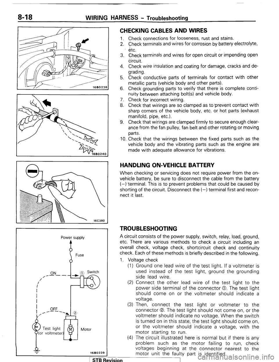
CHECKING CABLES AND WIRES
1. Check connections for looseness, rust and stains.
2. Check terminals and wires for corrosion by battery electrolyte,
$tc.
3. Check terminals and wires for open circuit or impending open
circuit.
4. Check wire insulation and coating for damage, cracks and de-
grading.
5. Check conductive parts of terminals for contact with other
metallic parts (vehicle body and other parts).
6. Check grounding parts to verify that there is complete conti-
nuity between attaching bolt(s) and vehicle body.
7. Check for incorrect wiring.
8. Check that wirings are so clamped as to ‘prevent contact with
sharp corners of the vehicle body, etc. or hot parts (exhaust
manifold, pipe, etc.).
9. Check that wirings are clamped firmly to secure enough clear-
ance from the fan pulley, fan belt and other rotating or moving
parts.
10. Check that the wirings between the fixed parts such as the
vehicle body and the vibrating parts such as the engine are
made with adequate allowance for vibrations.
HANDLING ON-VEHICLE BAlTERY
When checking or servicing does not require power from the on-
vehicle battery, be sure to disconnect the cable from the battery
(-)terminal. This is to prevent problems that could be caused by
shorting of the circuit. Disconnect the (-) terminal first and recon-
nect it last.
TROUBLESHOOTING
A circuit consists of the power supply, switch, relay, load, ground,
etc. There are various methods to check a circuit including an
overall check, voltage check, shortcircuit check and continuity
check. Each of these methods is briefly described in the following.
1. Voltage check
(1) Ground one lead wire of the test light. If a voltmeter is
used instead of the test light, ground the grounding
side lead wire.
(2) Connect the other lead wire of the test light to the
power side terminal of the connector 0. The test light
should come on or the voltmeter should indicate a
voltage.
(3) Then, connect the test light or voltmeter to the
connector (3,. The test light should not come on, or the
voltmeter should indicate no voltage. When the switch
is turned on in this state, the test light should come on,
or the voltmeter should indicate a voltage, with the
motor starting to run.
(4) The circuit illustrated here is normal but if there is any
problem such as the motor failing to run, check
voltages beginning at the connector nearest to the
motor unit the faulty part is identified. 1 ST6 Revision
Page 43 of 284
WIRING HARNESS - HOW BO Read Wiring Diagrams 8-23
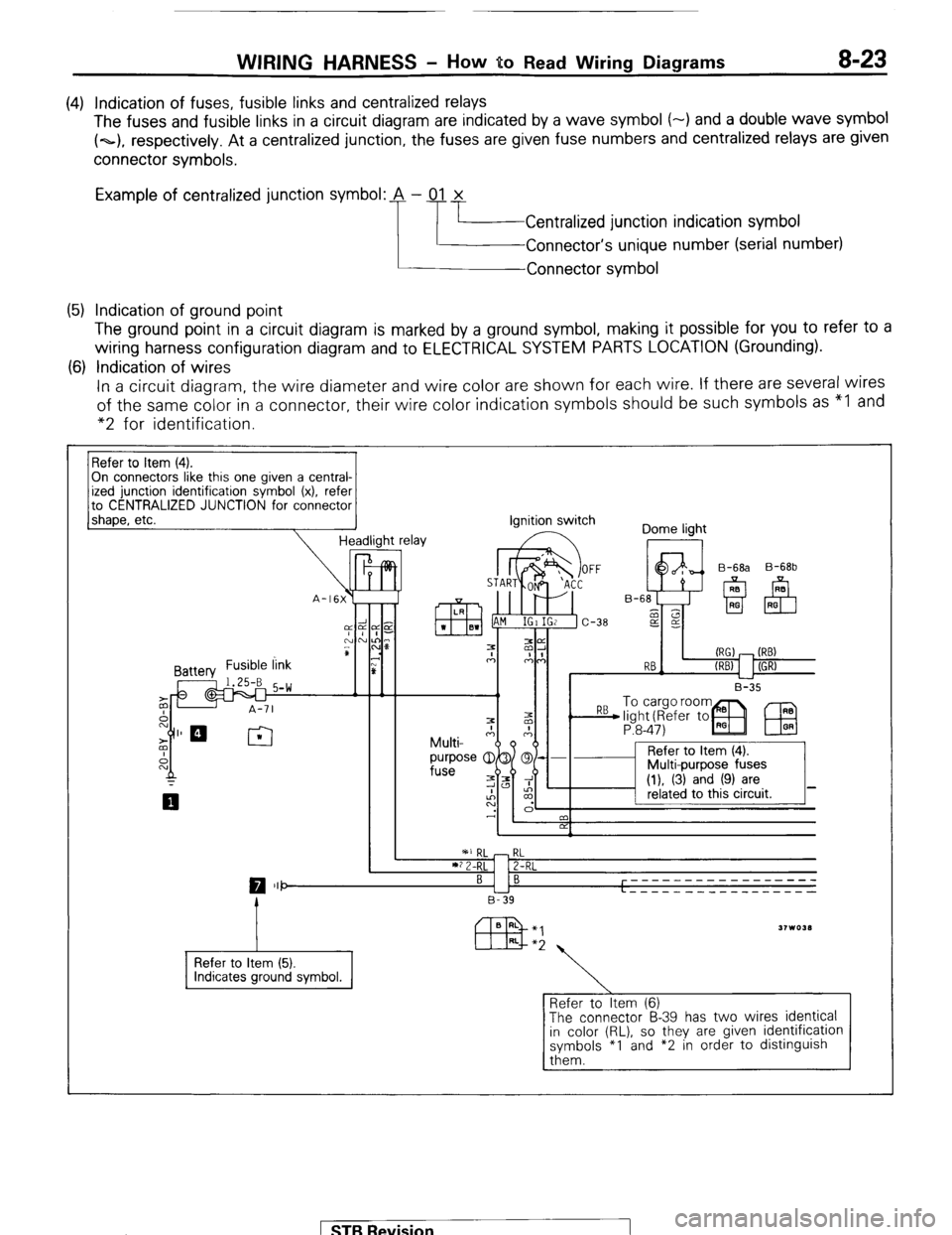
(4) Indication of fuses, fusible links and centralized relays
The fuses and fusible links in a circuit diagram are indicated by a wave symbol (-) and a double wave symbol
(~1, respectively. At a centralized junction, the fuses are given fuse numbers and centralized relays are given
connector symbols.
Example of centralized junction symbol: A - 01 x
Centralized junction indication symbol
Connector’s unique number (serial number)
Connector symbol
(5) Indication of ground point
The ground point in a circuit diagram is marked by a ground symbol, making it possible for you to refer to a
wiring harness configuration diagram and to ELECTRICAL SYSTEM PARTS LOCATION (Grounding).
(6) Indication of wires
In a circuit diagram, the wire diameter and wire color are shown for each wire. If there are several wires
of the same color in a connector, their wire color indication symbols should be such symbols as “I and
“2 for identification.
On connectors like this one given a central-
to CENTRALIZED JUNCTION for connector
1 shaoe. etc.
-I Headlight relay ignition switch
Dome light
I II I B-35 B-68b
P:8-47)
IEU
I ’ 2 I
RL
2-RL
0 III- BI B -----____________
L - - - - - _ _ _ _ _ __ _ _ _ _ _
B-39
Refer to Item (5).
Refer to Item (6)
The connector B-39 has two wires identical
in color (RL), so they are given identification
symbols *I and *2 in order to distinguish
them. 1 ST6 Revision
Page 44 of 284
8-24 WIRING HARNESS - How to Read Wiring Diagrams
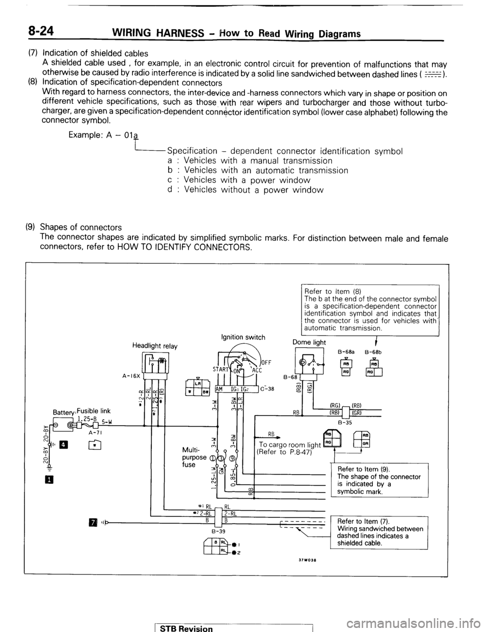
(7) Indication of shielded cables
A shielded cable used , for example, in an electronic control circuit for prevention of malfunctions that may
otherwise be caused by radio interference is indicated by a solid line sandwiched between dashed lines ( E).
(8) Indication of specification-dependent connectors
With regard to harness connectors, the inter-device and -harness connectors which vary in shape or position on
different vehicle specifications, such as those with rear wipers and turbocharger and those without turbo-
charger, are given a specification-dependent connector identification symbol (lower case alphabet) following the
connector symbol.
Example: A - Ola
Specification - dependent connector identification symbol
a : Vehicles with a manual transmission
b : Vehicles with an automatic transmission
c : Vehicles with a power window
d : Vehicles without a power window
(9) Shapes of connectors
The connector shapes are indicated by simplified symbolic marks. For distinction between male and female
connectors, refer to HOW TO IDENTIFY CONNECTORS.
Refer to Item (8)
The b at the end of the connector symbol
is a specification-dependent connector
identification
symbol and indicates that
the connector is used for vehicles with’
automatic transmission.
Headlight relay Ignition
switch I Dome light
B-68a B-68b STB Revision
Page 48 of 284
8-28 WIRING HARNESS - Engine Compartment
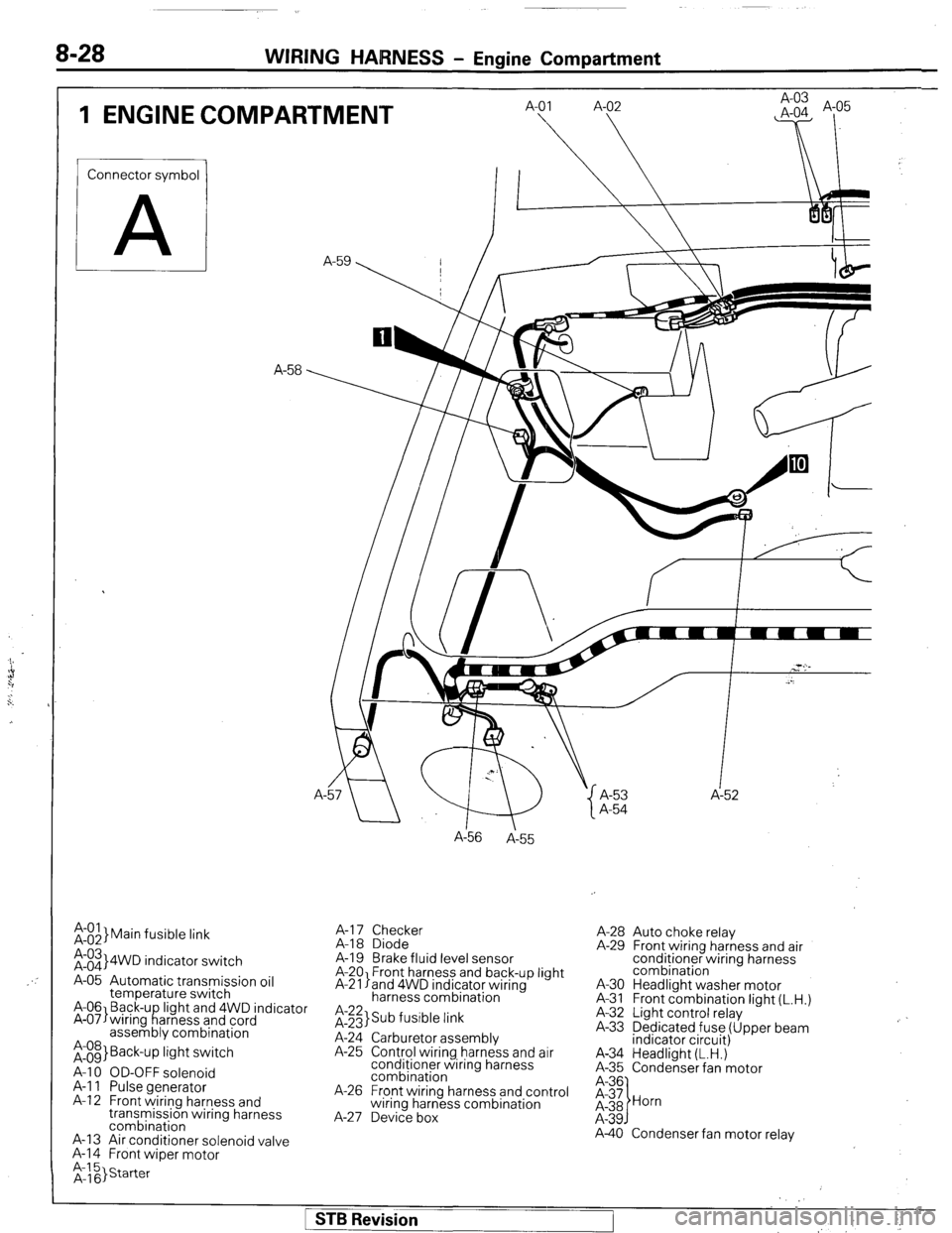
1 ENGINE COMPARTMENT
Connector symbol
A
;:::I Main fusible link
;:::I 4WD indicator switch
A-05 Automatic transmission oil
temperature switch
A-06 Back-u light and 4WD indicator
A-07)wiring f!arness and cord
assembly combination
;:g> Back-up light switch
A-l 0 OD-OFF solenoid
A-l 1 Pulse generator
A-l 2 Front wiring harness and
transmission wiring harness
combination
A-13 Air conditioner solenoid valve
A-l 4 Front wiper motor A-
A156
A-55
A-l 7 Checker
A-18 Diode
A-19 Brake fluid level sensor
A-20 Front harness and back-up light
A-21 land 4WD indicator wiring
harness combination
it;;> Sub fusible link
A-24 Carburetor assembly
A-25 Control wiring harness and air
conditioner wiring harness
combination
A-26 Front wiring harness and control
wiring harness combination
A-27 Device box A-53 A-52
A-54
A-28 Auto choke relay
A-29 Front wiring harness and air
conditioner wiring harness
combination
A-30 Headlight washer motor
A-31 Front combination light (L.H.)
A-32 Light control relay
A-33 Dedicated fuse (Upper beam
indicator circuit)
A-34 Headlight (L.H.)
A-35 Condenser fan motor
A-40 Condenser fan motor relay
1 STB Revision
Page 52 of 284
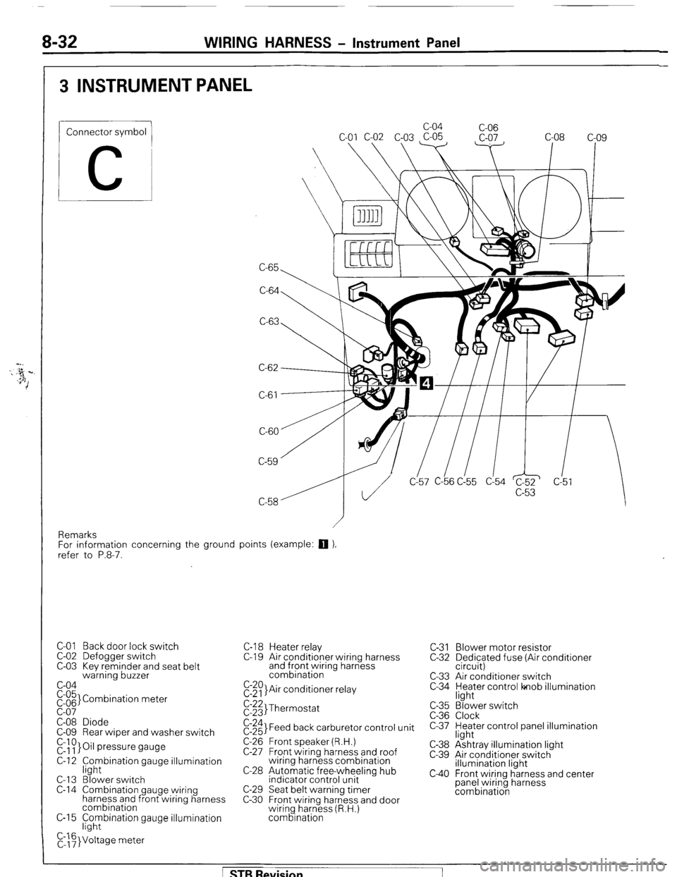
8-32 WIRING HARNESS - Instrument Panel
3 INSTRUMENT PANEL
Connector symbol
C
C-65 c-04
C-06
C-64
C-63
C-61
CL57 C-b6 C!55 d54 c!5
Remarks
For information concerning the ground points (example:
q ),
refer to P.8-7.
C-01 Back door lock switch
C-02 Defogger switch
C-03 Kev reminder and seat belt
warning buzzer
c-04
pi;’ Combination meter
C-08 Diode
C-09 Rear wiper and washer switch
r&~}Oil pressure gauge
C-12 f;hybination gauge illumination
C-l 3 Blower switch
C-14 Combination gauge wiring
harness and front wiring harness
combination
C-15 F;hybination gauge illumination
C,::F}Voltage meter C-l 8 Heater relay
C-l 9 Air conditioner wiring harness
and front wiring harness
combination
E:$)}Air conditioner relay C-31 Blower motor resistor
C-32 Dedicated fuse (Air conditioner
circuit)
C-33 Air conditioner switch
C-34 yl;Jer control lonob illumination
$:;;I Thermostat
$:;;I Feed back carburetor control unit
C-26 Front speaker (R.H.)
C-27 Front wiring harness and roof
wiring harness combination
C-28 Automatic free-wheeling hub
indicator control unit
C-29 Seat belt warning timer
C-30 Front wiring harness and door
wiring harness (R.H.)
combination c-35
C-36
c-37
C-38
c-39
c40
“3’ ‘. Blower switch
Clock
Heater control panel illumination
light
Ashtray illumination light
Air conditioner switch
illumination light
Front wiring harness and center
panel wiring harness
combination
[ STB Revision
Page 53 of 284
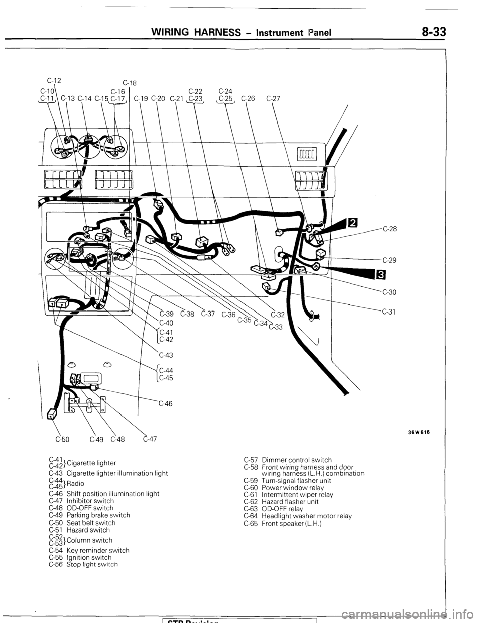
WIRING HARNESS - Instrument Panel 8-33
cy50 C149 Cl48 c-47
El$,}Cigarette lightet
C-43 Cigarette lighter illumination light
E::$ Radio
C-46 Shift position illumination light
C-47 Inhibitor switch
C-48 OD-OFF switch
C-49 Parking brake switch
C-50 Seat belt switch
C-51 Hazard switch
E3 Column switch
C-54 Key reminder switch
C-55 Ignition switch
C-56 Stop light switch C-57 Dimmer control switch
C-58 Front wiring harness and door
wiring harness (L.H.) combination
C-59 Turn-signal flasher unit
C-60 Power window relay
C-61 Intermittent wiper relay
C-62 Hazard flasher unit
C-63 OD-OFF relay
C-64 Headlight washer motor relay
C-65 Front speaker (L.H.)
Ision
Page 60 of 284
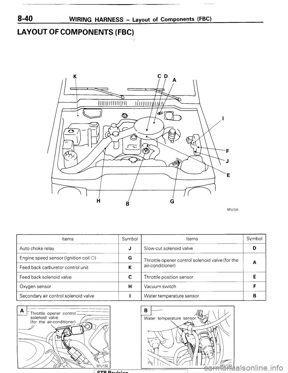
8-40 WIRING HARNESS - Layout of Components WC)
LAYOUT OFCOMPONENJS [FBC)
CD
II A
5FU131
Items
Symbol Items Symbol
Auto choke relay J Slow-cut solenoid valve D
Engine speed sensor (Ignition coil 0)
Feed back carburetor control unit G
Throttle opener control solenoid valve (for the
A
K air-conditioner)
Feed back solenoid valve
I
C Throttle position sensor
I E
Oxygen sensor
I H Vacuum switch
I F
Secondary air control solenoid valve
I I 1 Water temperature sensor
I B
Throttle opener contr
solenoid valve
Page 63 of 284
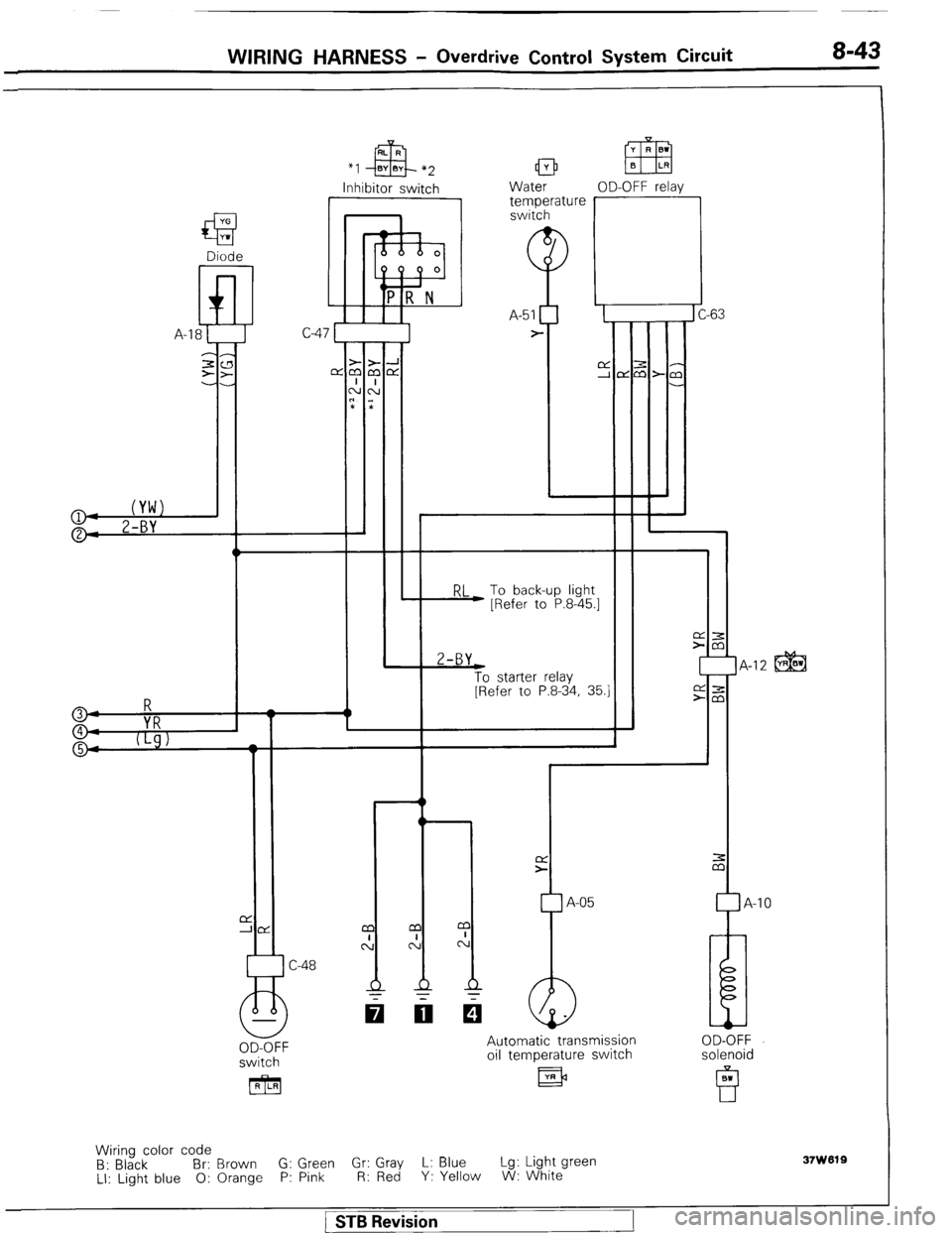
WIRING HARNESS - Overdrive Control System Circuit 8-43
*I
Inhibitor switch
I Water OD-OFF relav 1 temperature r -63 C-
RL To back-up light
) [Refer to P.8-45.1 2-BY
t
To starter relay
[Refer to P.8-34, 35.1 IA-12 @@ 3
4
VRR
9 5
I t
L
1
r
A-05 -10
switch
[RILRI Automatic transmission
oil temperature switch
llR)3 OD-OFF
solenoid
Wiring color code
B: Black Br: Brown G: Green G;; ;ZJ L: Blue Lg: Light green
LI: Light blue 0: Orange P: Pink Y: Yellow W: White
37w019
1 STB Revision
Page 65 of 284
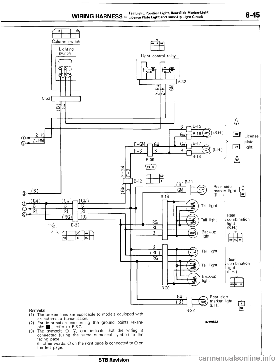
WIRING HARNESS Tail Light, Position Light, Rear Side Marker Light.
- License Plate Light and Back-Up Light Circuit 8-45
fl!FEEl
Column switch
I
Lighting
switch
Light control relay
F-GW -GW
B-l 2
B-l 1
Tail light
Rear
$ combination
light
(R.H.) Tail light
Back-up
light
‘El3 RG RI. G
Tail light
Rear
combination
fight
(L.H.) Tail light
Back-up
light
I GW
IBl Rear side
Remarks
B-22
(1) The broken lines are applicable to models equipped wrtn
an automatic transmission.
(2) For information concerning the ground points (exam-
37W023 , I
- ple: 0 ). refer to P.8-7.
(3) The symbols 0, 0, etc. indicate that the wiring is
connected (using the same numerical symbol) to the
facing page. -
(In other words, 0 on the right page is connected to 0 on
the left page.)
) STB Revision
Page 66 of 284
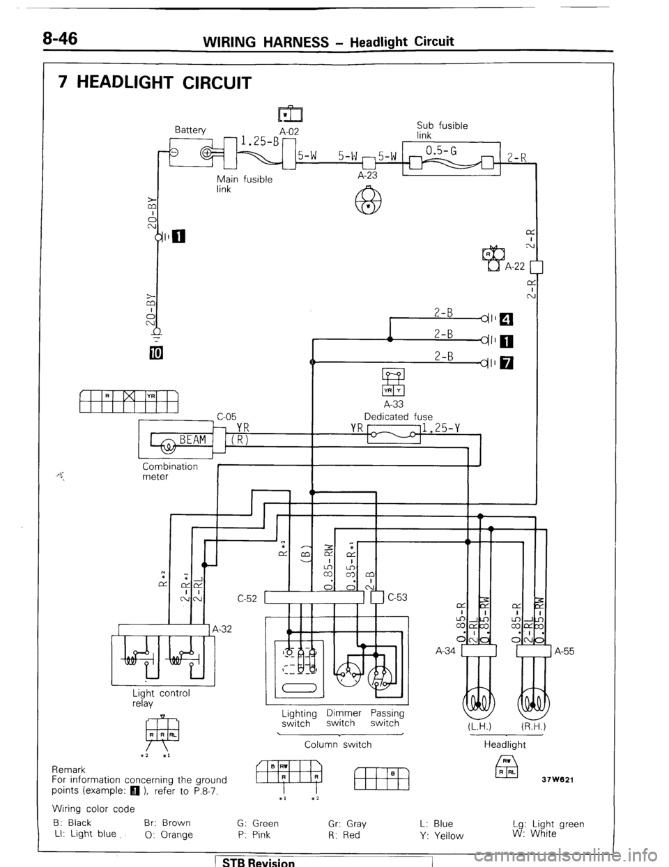
8-46 WIRING HARNESS - Headlight Circuit
7 HEADLIGHT CIRCUIT
M-!l
Battery
A-02 Sub fusible
-1.25-B- link
1 5-w 0.5-G
5-w m5-w M
2-R U
Main fusible A-23
link
F
R YR
il I I vi I! I‘i
1 c-05
1 BEAM 1 ('R;
Combination
meter
2-B
[ES 71' 0
$$J
A-33
Dedicated fuse
J
“I w C-52
-32
Light control
relay
Lighting Dimmer Passing
switch switch switch
Column‘ switch Headlight
Remark
For information concerning the ground
POintS (example: 0 ), refer to P.8-7.
9 m x2
Wiring color code
B: Black Br: Brown
G: Green Gr: Gray
Ll: Light blue
0: Orange P: Pink R: Red A-34
(L.H.) (R.H.)
1
A-55
37W621
L: Blue
Y: Yellow Lg: Light green
W: White
1 STB Revision