relay MITSUBISHI MONTERO 1987 1.G Service Manual
[x] Cancel search | Manufacturer: MITSUBISHI, Model Year: 1987, Model line: MONTERO, Model: MITSUBISHI MONTERO 1987 1.GPages: 284, PDF Size: 14.74 MB
Page 200 of 284
WIPER AND WASHER SYSTEM - Headlight Washer
INSPECTION
WASHER MOTOR AND PUMP
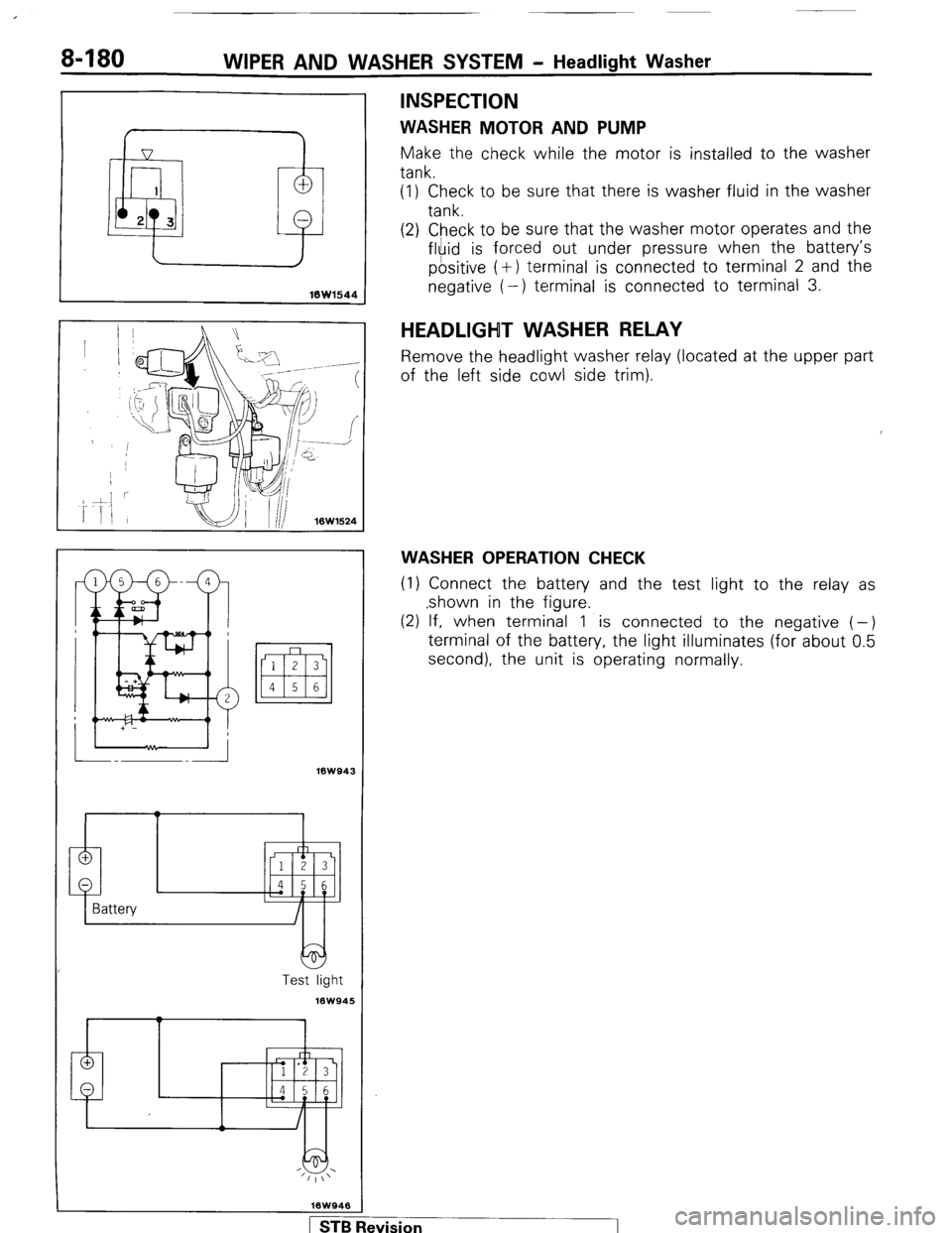
Make the check while the motor is installed to the washer
tank.
(1) Check to be sure that there is washer fluid in the washer
tank.
16Wl544
(2) Check to be sure that the washer motor operates and the
fluid is forced out under pressure when the battery’s
positive (+) terminal is connected to terminal 2 and the
negative (-) terminal is connected to terminal 3.
18W943
Test light
16W945
HEADLIGHT WASHER RELAY
Remove the headlight washer relay (located a
of the left side cowl side trim). It the upper part
WASHER OPERATION CHECK
(1) Connect the battery and the test light to the relay as
,shown in the figure.
(2) If, when terminal 1 is connected to the negative (-)
terminal of the battery, the light illuminates (for about 0.5
second), the unit is operating normally.
1 STB Revision -1
Page 213 of 284
AUDIO SYSTEM - Specifications 8-193
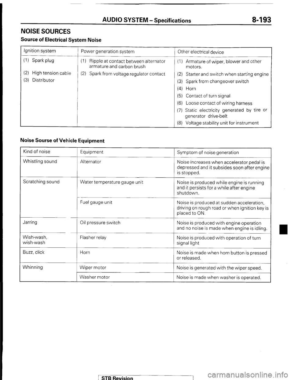
NOISE SOURCES
Source of Electrical System Noise
Ignition system
(1) Spark plug
(2) High tension cable
(3) Distributor Power generation system
(1) Ripple at contact between alternator
armature and carbon brush
(2) Spark from voltage regulator contact
!
Other electrical device
(1) Armature of wiper, blower and other
motors.
(2) Starter and switch when starting engine
(3) Spark from changeover switch
(4) Horn
(5) Contact of turn signal
(6) Loose contact of wiring harness
(7) Static electricity generated by tire or
generator drive-belt
(8) Voltage stability unit for instrument
Noise Sourse of Vehicle Equipment
Kind of noise
Whistling sound Equipment
Alternator Symptom of noise generation
Noise increases when accelerator pedal is
depressed and it subsides soon after engine
is stopped.
Scratching sound
Water temperature gauge unit Noise is produced while engine is running
and it persists for a while after engine
shutdown.
Fuel gauge unit Noise is produced at sudden acceleration,
driving on rough road or when ignition key is
placed to ON.
Jarring
Wish-wash,
wish-wash
Buzz, click Oil pressure switch
Flasher relay
Horn
Wiper motor
Washer motor Noise is produced with engine operation
and no noise is made when engine is idling.
Noise is produced with operation of turn
signal light
Noise is made when horn button is pressed
or released.
Whinning Noise is generated with the wiper speed.
Noise is made when washer is operated.
STB Revision
Page 225 of 284
BACK DOOR WINDOW DEFOGGER - Circuit Diagram 8-205
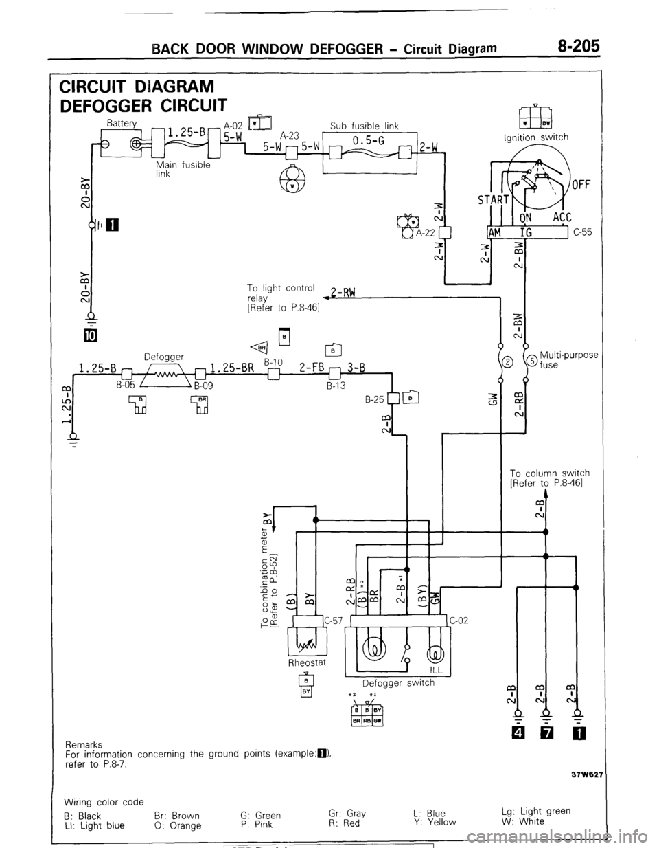
CIRCUIT DUAGRAM
DEFOGGER CIRCUIT -t IDI L
m
- H-UL Ll&J Sub fusible link
5-w A-23 0.5-G 1 5-w"5'w m
z-w ,
u
fusible ignition switch
Main
link
To light control
relay w zmR~
[Refer to P.8-461
q--l-
2 @fuse
i
Multi-purpose m
E
c:
t
To column switch
[Refer to P.8-461
1.25-B
a
c!
Rheostat
Defogger switch a
cl
31 W02:
Remarks
For information concerning the ground points (example:D).
refer to P.8-7.
Wiring color code
B: Black Br: Brown G: Green Gr: Gray L: Blue Lg: Light green
LI: Light blue 0: Orange P: Pink R: Red Y: Yellow W: White STB Revision
Page 258 of 284
24-22 AIR-CONDITIONING - Special TOOIS / Troubleshooting
SPECIAL TOOLS
Tool (Number and name)
MB990783-01
Steering/pinion gear
remover/installer Use
Installation of seal plate
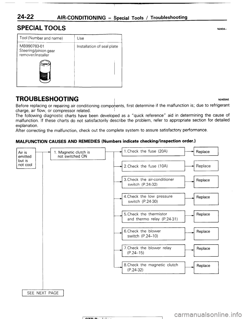
TROUBLESHOOTING N24EBAE
Before replacing or repairing air conditioning compofents, first determine if the malfunction is; due to refrigerant
charge, air flow, or compressor related.
The following diagnostic charts have been developed as a “quick reference” aid in determining the cause of
malfunction. If these charts do not satisfactorily describe the problem, refer to appropriate section for detailed
explanation.
N24DA.-
After correcting the malfunction, check out the complete system to assure satisfactory performance.
MALFUNCTION CAUSES AND REMEDIES (Numbers indicate checking/inspection order.)
1 not cool 1 Air is
emitted
but is * 1. Magnetic clutch is
not switched ON
SEE NEXT PAGE 1 Replace
1
I
I I
-4 2.Check the fuse (IOA)
t-l Replace
I
I I
I ,
I
3,Check the air-conditioner
__) Replace
switch (P.24-32)
I
4.Check the low pressure
switch (P.24-30) - Replace
---L 5.Check the thermistor
- Replace
and therm0 relay (P.24-31)
- 6.Check the blower
switch (P.24-10) - Replace
-i 7.Check the blower relay
M Replace
(P.24-15)
8.Check the magnetic clutch
(P.24-32) Replace
I
1 STB Revision
Page 261 of 284
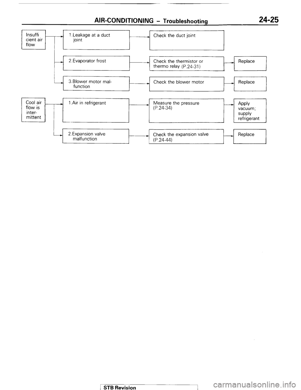
AIR-CONDITIONING - Troubleshooting 24-25
lnsuffi
cient air
flow ) 1 .Leakage at a duct
joint . Check the duct joint
- 2.Evaporator frost
D Check the thermistor or
therm0 relay (P.24-31) A Replace
3.Blower motor mal-
function + Check the blower motor - Replace
+
Cool air
.
flow is 1 .Air in refrigerant ) Measure the pressure
(P.24-34) - Apply
inter- vacuum;
mittent supply
refrigerant
i--) 2.Expansion valve
malfunction Check the expansion valve
* (P.24-44) _ Replace STB Revision
Page 263 of 284
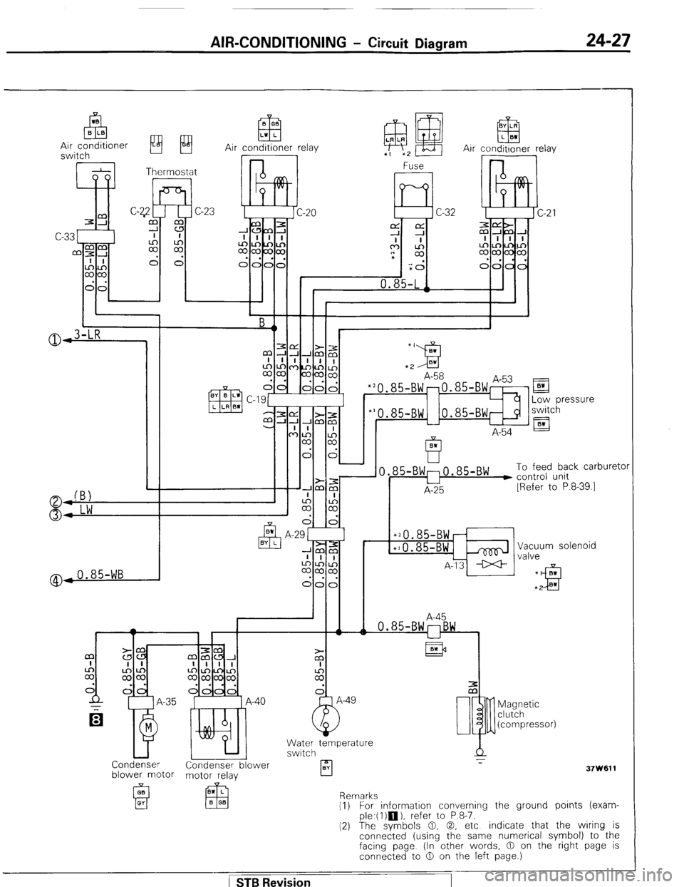
AIR-CONDITIONING - Circuit Diagram 24-27
Air conditioner relay
@,0.85-WB
El
Low pressure
switch
A-54 El
85-BW:0.85-BW ) To feed back carburetc
u control unit
A-25 [Refer to P.8-39.1
*20.85-BWr
*10.85-BWi& Vacuum solenoid
A-13 ++ valve
A-45
Condenser Condenser blower
blower motor motor relay
A
rl z-
BY
37W611 Magnetic
clutch
(compressor)
Remarks
(1) For information converning the ground points (exam-
ple.(l)m), refer to P.8-7.
(2) The symbols 0, 0, etc indicate that the wiring is
connected (using the same numerical symbol) to the
facing page (In other words, 0 on the right page is
connected to 0 on the left page.)
( STB Revision
Page 267 of 284
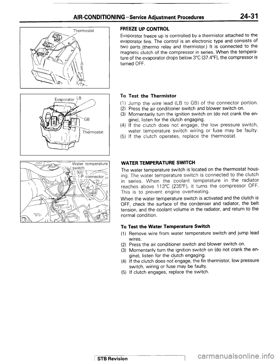
AIR-CONDITIONING-Service Adiustment Procedures 24-31
FREEZE UP CONTROL
Evaporator freeze up is controlled by a thermistor attached to the
evaporator fins. The control is an electronic type and consists of
two parts_(thermo relay and thermistor.) It is connected to the
magnetic clutch of the compressor in series. When the tempera-
ture of the evaporator drops below 3°C (37.4”F), the compressor is
turned OFF.
To Test the Thermistor
(1) Jump the wire lead (LB to GB) of the connector portion.
(2) Press the air conditioner switch and blower switch on.
(3) Momentarily turn the ignition switch on (do not crank the en-
gine), listen for the clutch engaging.
(4) If the clutch does not engage, the low pressure switch,
water temperature switch wiring or fuse may be faulty.
(5) If the clutch operates, replace the thermostat.
WATER TEMPERATURE SWITCH
The water temperature switch is located on the thermostat hous-
ing. The water temperature switch is connected to the clutch
in series. When the coolant temperature in the radiator
reaches above 113°C (235”F), it turns the compressor OFF.
This is to prevent engine overheating.
When the water temperature switch is activated and the clutch is
OFF, check the surface of the condenser and radiator, the belt
tension, and the coolant volume in the radiator, and return to the
normal condition.
To Test the Water Temperature Switch
(1) Remove wire from water temperature switch and jump lead
wires.
(2) Press the air conditioner switch and blower switch on.
(3) Momentarily turn the ignition switch on (do not crank the en-
gine), listen for the clutch engaging.
(4) If the clutch does not-engage, the fin thermistor, low pressure
switch, wiring or fuse may be faulty.
(5) If clutch engages, replace the switch.
1 STB Revision
Page 280 of 284
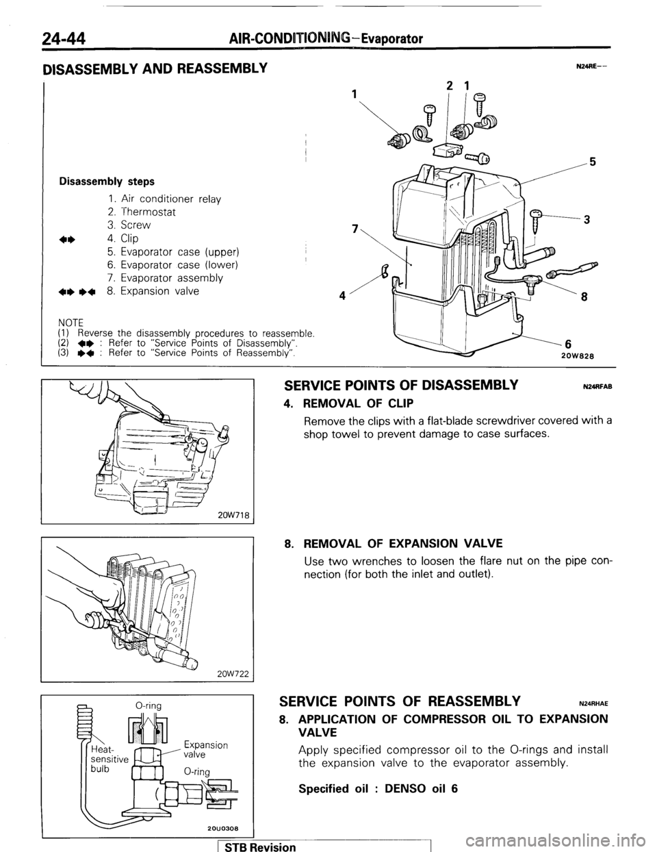
24-44 AIR-CONDOTIONING-Evaporator
DISASSEMBLY AND REASSEMBLY
1
Disassembly steps
1. Air conditioner relay
2. Thermostat
3. Screw
4* 4. Clip
5. Evaporator case (upper)
6. Evaporator case (lower)
7. Evaporator assembly
+e l + 8. Expansion valve
NOTE
(1) Reverse the disassembly procedures to reassemble.
(2) +e : Refer to “Service Points of Disassembly”.
(3) l + : Refer to “Service Points of Reassembly”.
N24RE-- -6
2OW828
2OW718
2ow722
a 0-rina
Expansion
valve
O-rim
SERVICE POINTS OF DISASSEMBLY
4. REMOVAL OF CLIP
N24RFAB Remove the clips with a flat-blade screwdriver covered with a
shop towel to prevent damage to case surfaces.
8. REMOVAL OF EXPANSION VALVE Use two wrenches to loosen the flare nut on the pipe con-
nection (for both the inlet and outlet).
SERVICE POINTS OF REASSEMBLY N24RHAE
8. APPLICATION OF COMPRESSOR OIL TO EXPANSION
VALVE Apply specified compressor oil to the O-rings and install
the expansion valve to the evaporator assembly.
Specified oil : DENS0 oil 6
1 STB Revision