relay MITSUBISHI MONTERO 1987 1.G Owner's Guide
[x] Cancel search | Manufacturer: MITSUBISHI, Model Year: 1987, Model line: MONTERO, Model: MITSUBISHI MONTERO 1987 1.GPages: 284, PDF Size: 14.74 MB
Page 98 of 284
8-78 CHARGING SYSTEM - Service Adiustment Procedures
80A
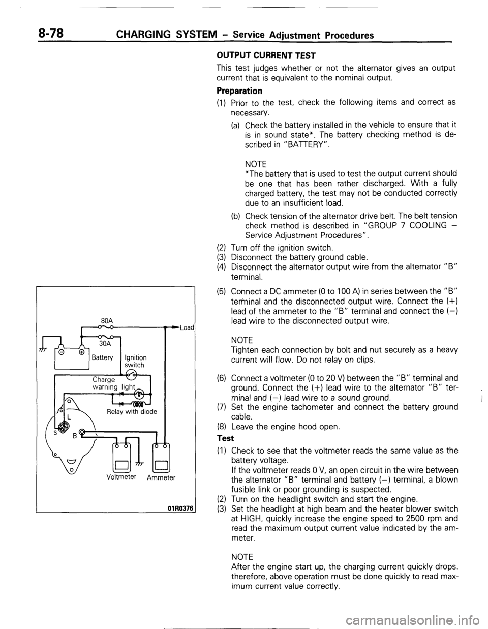
n
Relay with diode
Voltmeter
Ammeter Iad
176
OUTPUT CURRENT TEST
This test judges whether or not the alternator gives an output
current that is equivalent to the nominal output.
Preparation
(1) Prior to the test, check the following items and correct as
necessary.
(a) Check the battery installed in the vehicle to ensure that it
is in sound state*. The battery checking method is de-
scribed in “BATTERY”.
NOTE
*The battery that is used to test the output current should
be one that has been rather discharged. With a fully
charged battery, the test may not be conducted correctly
due to an insufficient load.
(b) Check tension of the alternator drive belt. The belt tension
check method is described in “GROUP 7 COOLING -
Service Adjustment Procedures”.
(2) Turn off the ignition switch.
(3) Disconnect the battery ground cable.
(4) Disconnect the alternator output wire from the alternator “B”
terminal.
(5) Connect a DC ammeter (0 to 100 A) in series between the “B”
terminal and the disconnected output wire. Connect the (+)
lead of the ammeter to the “B” terminal and connect the (-)
lead wire to the disconnected output wire.
NOTE
Tighten each connection by bolt and nut securely as a heavy
current will flow. Do not relay on clips.
(6) Connect a voltmeter (0 to 20 V) between the “B” terminal and
ground. Connect the (+) lead wire to the alternator “B” ter-
minal and (-) lead wire to a sound ground.
(7) Set the engine tachometer and connect the battery ground
cable.
(8) Leave the engine hood open.
Test
(1) Check to see that the voltmeter reads the same value as the
battery voltage.
If the voltmeter reads 0 V, an open circuit in the wire between
the alternator “B” terminal and battery (-) terminal, a blown
fusible link or poor grounding is suspected.
(2) Turn on the headlight switch and start the engine.
(3) Set the headlight at high beam and the heater blower switch
at HIGH, quickly increase the engine speed to 2500 rpm and
read the maximum output current value indicated by the am-
meter.
NOTE
After the engine start up, the charging current quickly drops.
therefore, above operation must be done quickly to read max-
imum current value correctly.
[ STB Revision
--I
Page 143 of 284
METERS AND GAUGES-Specifications
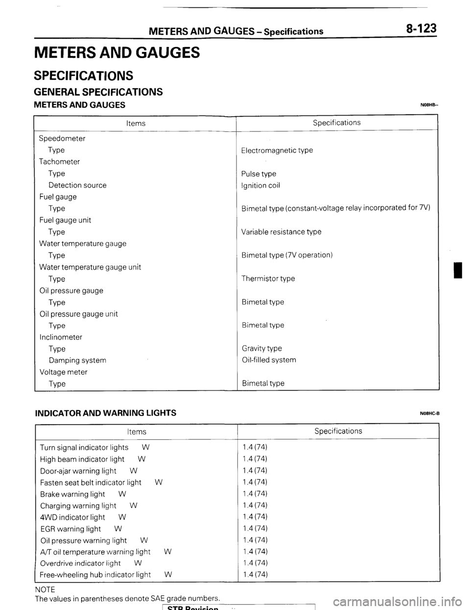
METERS AND GAUGES
8-123
SPECIFICATIONS
GENERAL SPECIFICATIONS
METERS AND GAUGES NOEHB-
Items
Speedometer
Type
Tachometer
Type
Detection source
Fuel gauge
Type
Fuel gauge unit
Type
Water temperature gauge
Type
Water temperature gauge unit
Type
Oil pressure gauge
Type
Oil pressure gauge unit
Type
Inclinometer
Type
Damping system
Voltage meter
Type Specifications
Electromagnetic type
Pulse type
Ignition coil
Bimetal type (constant-voltage relay incorporated for 7V)
Variable resistance type
Bimetal type (7V operation)
Thermistor type
Bimetal type
Bimetal type
Gravity type
Oil-filled system
Bimetal type
INDICATOR AND WARNING LIGHTS
NOEHC-B
Items Specifications
Turn signal indicator lights
W 1.4 (74)
High beam indicator light W 1.4 (74)
Door-ajar warning light W 1.4 (74)
Fasten seat belt indicator light W 1.4 (74)
Brake warning light W 1.4 (74)
Charging warning light W 1.4 (74)
4WD indicator light W 1.4 (74)
EGR warning light W 1.4 (74)
Oil pressure warning light W 1.4 (74)
A/T oil temperature warning light
W 1.4 (74)
Overdrive indicator light
W 1.4 (74)
Free-wheeling hub indicator light W 1.4 (74)
NOTE
The values in parentheses denote SAE grade numbers.
1 STB Revision ”
Page 163 of 284
LIGHTING SYSTEM - Specifications 8-143
LIGHTING SYSTEM
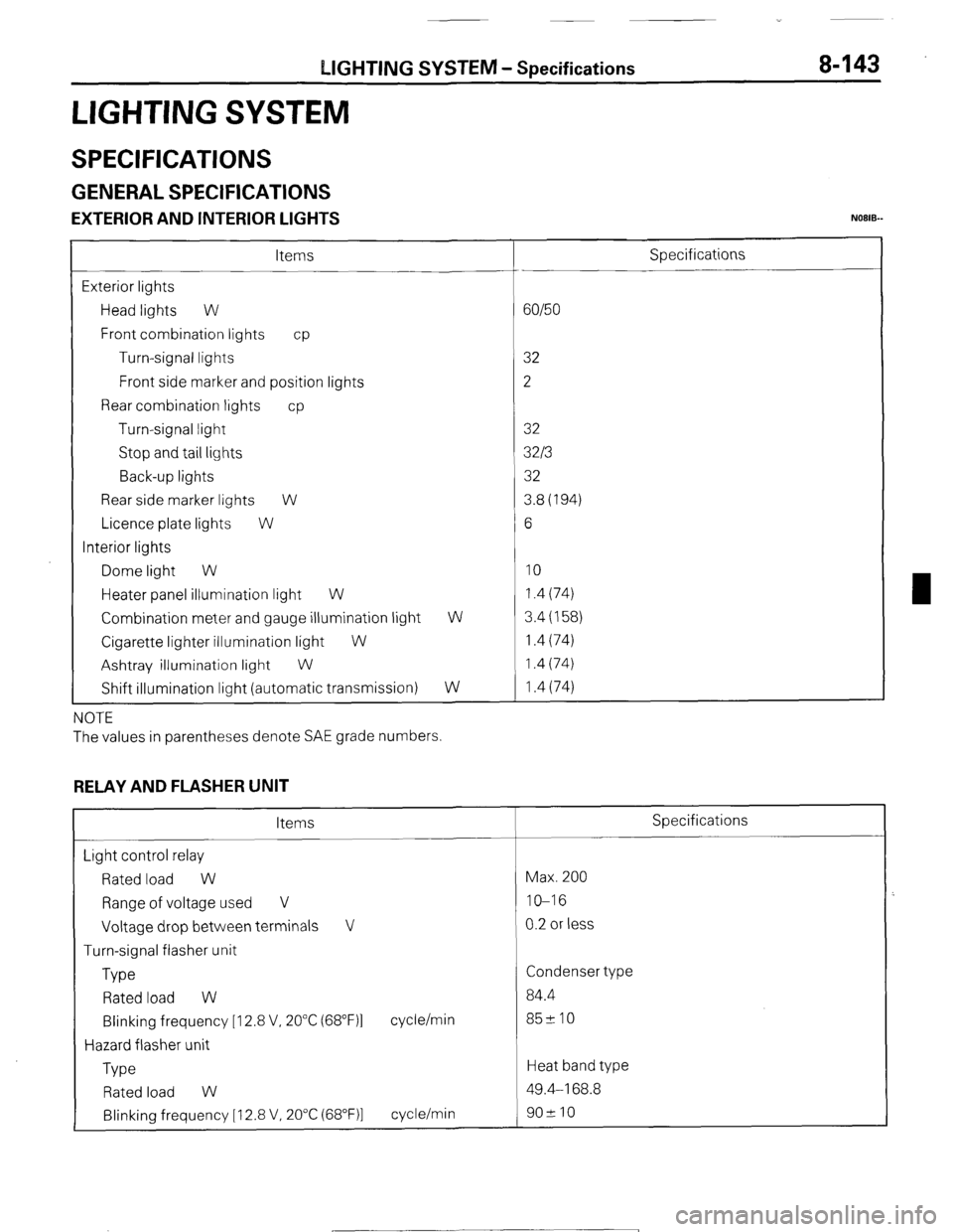
SPECIFICATIONS
GENERAL SPECIFICATIONS
EXTERIOR AND INTERIOR LIGHTS NOEIB-
Items
Exterior lights
Head lights W
Front combination lights cp
Turn-signal lights
Front side marker and position lights
Rear combination lights cp
Turn-signal light
Stop and tail lights
Back-up lights
Rear side marker lights W
Licence plate lights W
Interior lights
Dome light W
Heater panel illumination light W
Combination meter and gauge illumination light
Cigarette lighter illumination light
W
Ashtray illumination light
W
Shift illumination light (automatic transmission) W
W
NOTE
The values in parentheses denote SAE grade numbers.
RELAY AND FLASHER UNIT
Items
Light control relay
Rated load W
Range of voltage used V
Voltage drop between terminals V
Turn-signal flasher unit
Type
Rated load W
Blinking frequency [I 2.8 V, 20°C (68”F)l
Hazard flasher unit
Type cycle/min
Rated load W
Blinking frequency [ 12.8 V, 20°C (68”F)l cycle/min Specifications
60/50
32
2
32
32/3
32
3.8(194)
6
10 1.4 (74)
3.4 (158)
1.4 (74)
1.4 (74)
1.4 (74)
Specifications
Max. 200
IO-16
0.2 or less
Condenser type
84.4
85210
Heat band type
49.4-168.8
902 10
1 STB Revision
Page 169 of 284
LIGHTING SYSTEM - Circuit Diagram 8-149
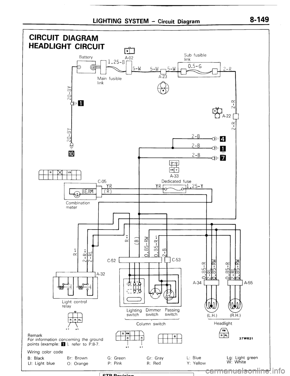
CIRCUIT DIAGRAM
HEADLIGHT CIRCUIT m
Battery
A-02 Sub fusible
link
0.5-G
5-v m5-w m 2-R
L-l
Main fusible A-23
lrnk
z
A
2-B
dl
r 2-B
I dl
ItfYH
A-33
c-05 Dedicated fuse
YR[ 11.25-Y
1-1
I
Combination
meter
I I
Wlir,L n
*
7
.-32 A
I
A-55
I
Lighting Dimmer Passing
switch switch switch
Column switch Lrght control
relay
FP R R RL
x2 XI
J
(LTH.) (R.H.)
Headlight
37W621 Remark
For information concerning the ground
points (example:
q ), refer to P.8-7.
Wiring color code
B: Black Br: Brown G: Green Gr: Gray
LI: Light blue 0: Orange P: Pink R: Red L: Blue
Y: Yellow Lg: Light green
W: White
/ STB Revision
Page 171 of 284
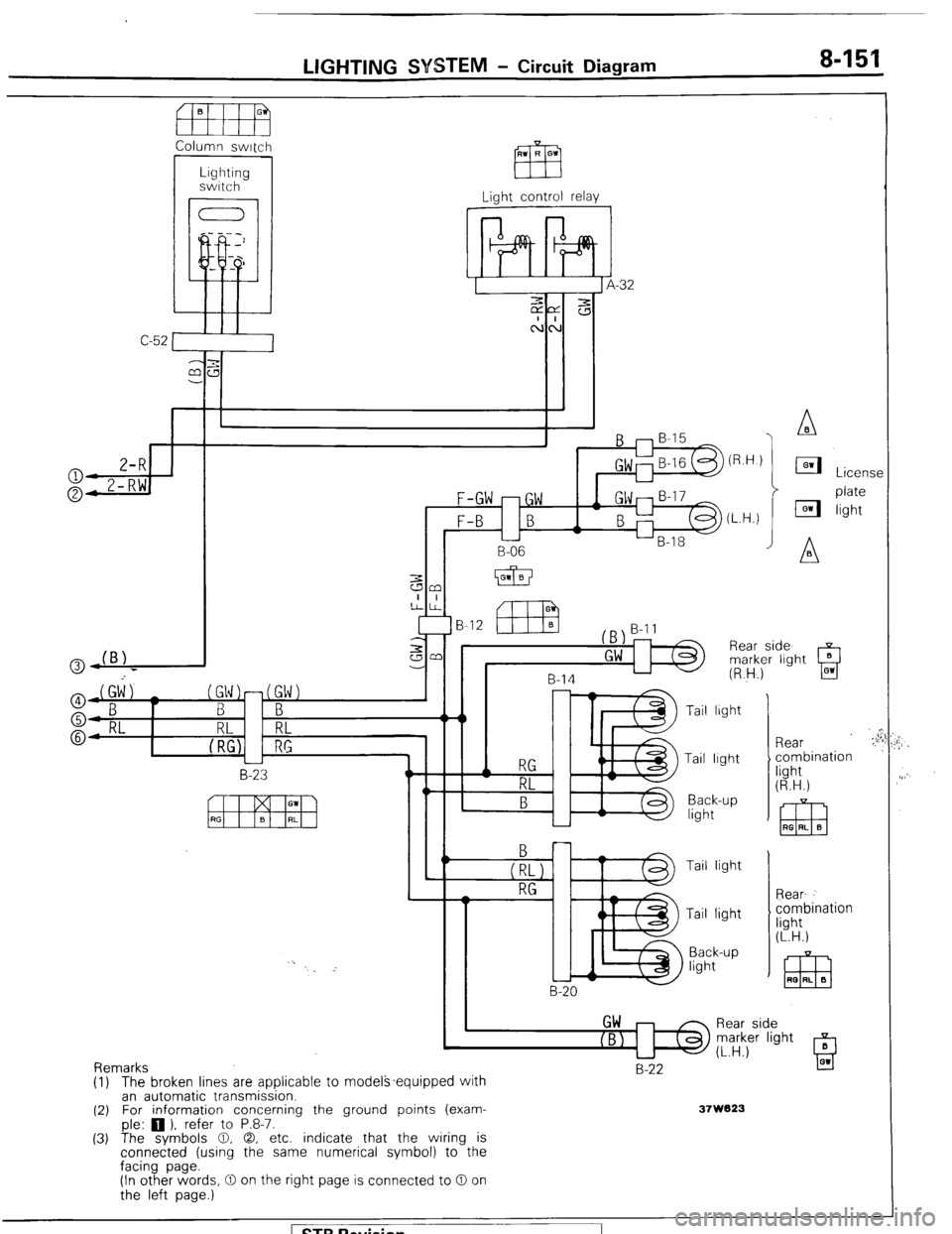
LIGHTING SYSTEM - Circuit Diagram 8-154
Column switch
C-52 Light control relay
1
-32
J
F-GW -GW
F-B B
L
B-06
B-12
B-14
L-l5 B-20 Tail light
Tail lrght
Back-up
light
Tail light
Tail light
Back-up
light Rear
combination
light
(R.H.)
Rear
combination
light
(L.H.)
Rear side
marker light
(L.H.)
Remarks
(1) (2)
(3) The broken lines are applicable to models~equipped with
an automatic transmission.
For information concerning the ground points (exam-
ple: 0 ). refer to P.8-7. B-22
37W823
The symbols 0, 0, etc. indicate that the wiring is
connected (using the same numerical symbol) to the
facing page.
(In other words, 0 on the right page is connected to 0 on
the left page.)
) STB Revision
Page 178 of 284
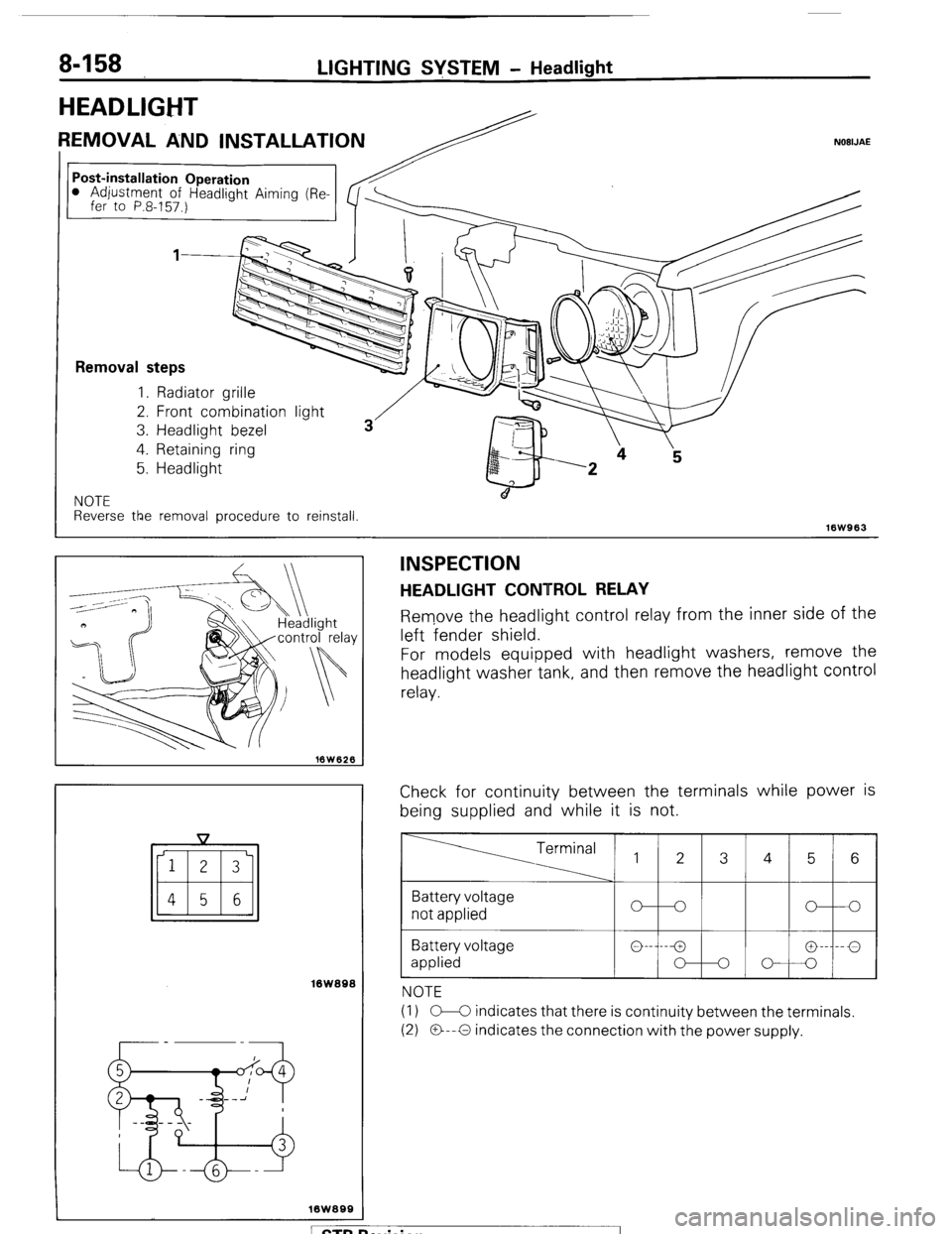
8-158 LIGHTING SYSTEM - Headlight
Post-installation Operation l Adjustment of Headliaht Aimina (
HEADLIGHT
REMOVAL AND INSTALLATION NOBIJAE
( fer to P.8-157.) Removal steps
1. Radiator grille
2. Front combinatior
3. Headlight bezel
4. Retaining ring
5. Headlight
I light
NOTE
Reverse the removal procedure to reinstall.
16W963
iswasa
INSPECTION
HEADLIGHT CONTROL RELAY
Remove the headlight control relay from the inner side of the
left fender shield.
For models equipped with headlight washers, remove the
headlight washer tank, and then remove the headlight control
relay.
Check for continuity between the terminals while power is
being supplied and while it is not. Terminal 1 2 3 4 5 6
Battery voltage
not applied
Battery voltage
applied
NOTE
(I 1 C-C indicates that there is continuity between the terminals.
(2) O--O indicates the connection with the power supply.
ewision I
Page 183 of 284
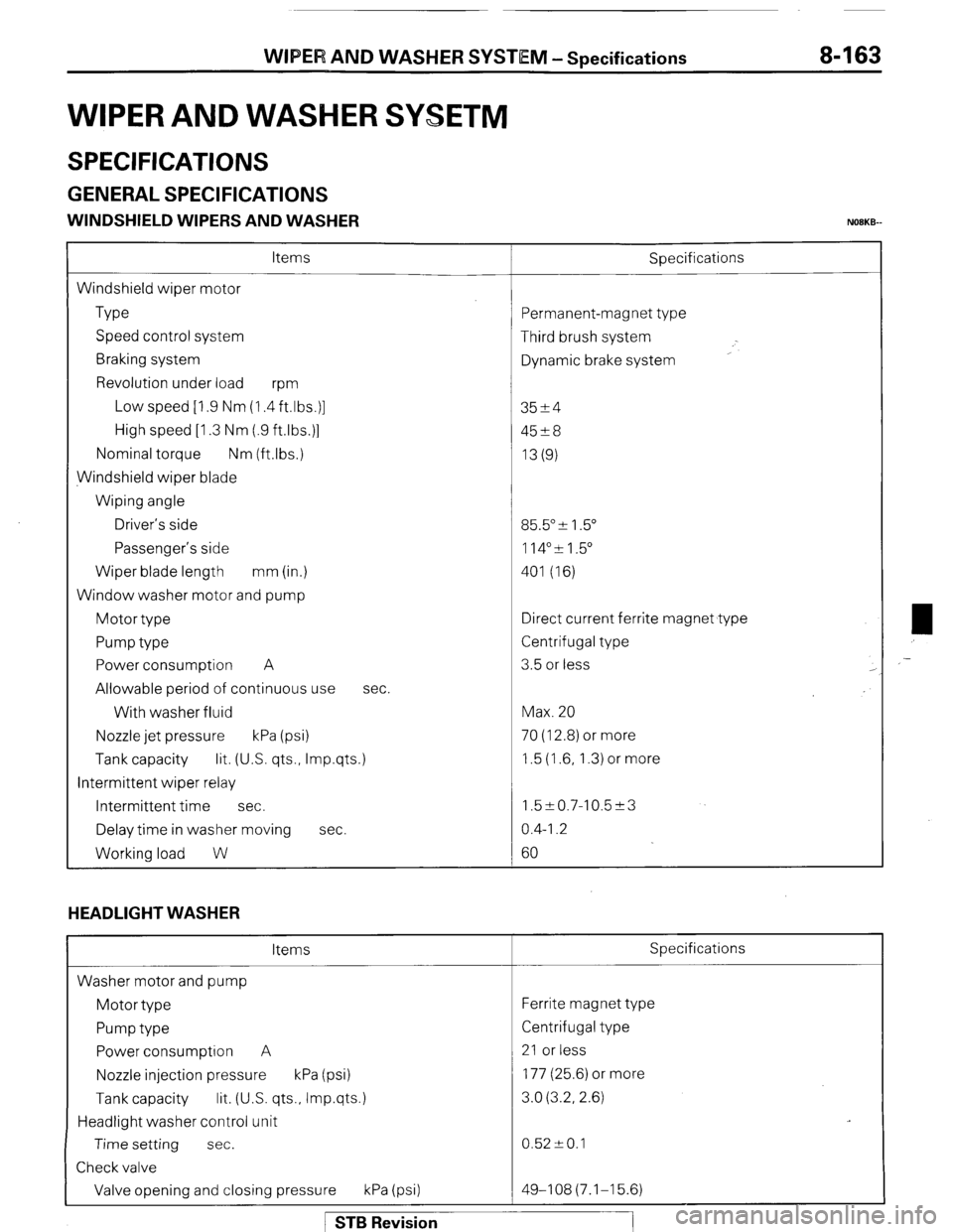
WIPER AND WASHER SYSTEM -Specifications 8-163
WIPER AND WASHER SYSETM
SPECIFICATIONS
GENERAL SPECIFICATIONS
WINDSHIELD WIPERS AND WASHER NOBKB-
Items
Windshield wiper motor
Type
Speed control system
Braking system
Revolution under load
wm
Low speed [I .9 Nm (1.4 ft.lbs.)]
High speed [I .3 Nm (.9 ftlbs.)]
Nominal torque Nm (ftlbs.)
Windshield wiper blade
Wiping angle
Driver’s side
Passenger’s side
Wiper blade length mm (in.)
Window washer motor and pump
Motor type
Pump type
Power consumption A
Allowable period of continuous use
With washer fluid
Nozzle jet pressure kPa (psi) Sbecifications
sec.
Tank capacity lit. (US. qts., Imp.qts.)
Intermittent wiper relay
Intermittent time sec.
Delay time in washer moving sec.
Working load W
HEADLIGHT WASHER
Items
Washer motor and pump
Motor type
Pump type
Power consumption A
Nozzle injection pressure kPa (psi)
Tank capacity lit. (U.S. qts., Imp.qts.)
Headlight washer control unit
Time setting sec.
Check valve
Valve opening and closing pressure kPa (psi) ‘ermanent-magnet type
Third brush system
Dynamic brake system
3524
45?8
13(g)
35.5” & 1.5”
114”51.5”
401 (16)
Iirect current ferrite magnet type
Zentrifugal type
3.5 or less
Max. 20
70 (12.8) or more
1.5 (1.6, 1.3) or more
1.5~0.7-10.5~3
0.4-I .2
60
Specifications
Ferrite magnet type
Centrifugal type
21 or less
177 (25.6) or more
3.0 (3.2, 2.6)
0.52 -+ 0.1
49-108(7.1-15.6) ,-
1 STB Revision
Page 188 of 284
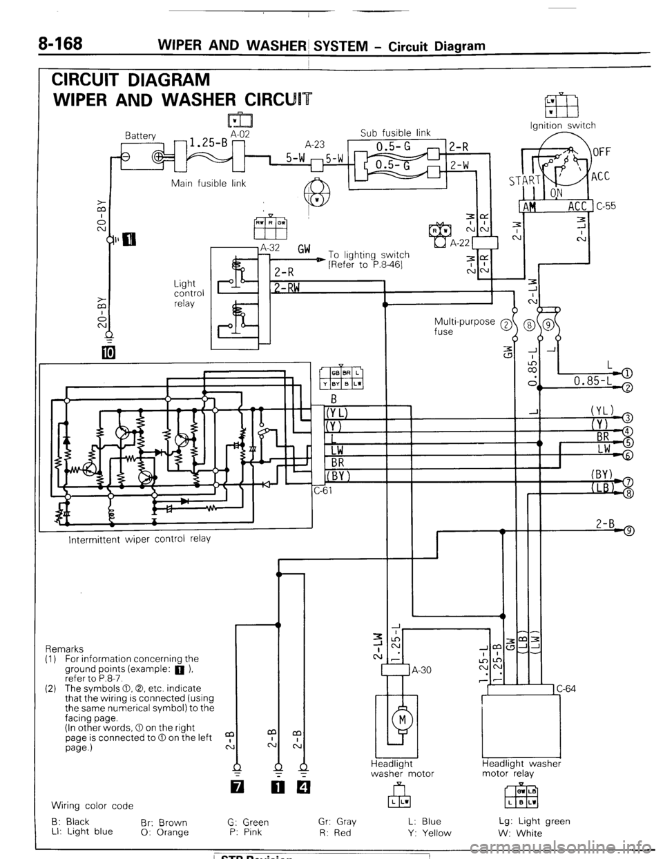
8468 WIPER AND WASHERS SYSTEM - Circuit Diagram
CIRCUIT DIAGRAM
WIPER AND WASHER CIRCU
Ignition switch
lattery
-1.SBAz2 Sub fusible link
A-23
0.5-G
1 5-w m5-w
U
2-R
Z-W
Main fusible link A IL
J.
c
7
C
-
-
-
-
-
-
J A
:
II,
L
.
> 0.85-L '
Light
control
relay P I? 1 -RW ,
Multi-purpose @
fuse
2-B 9
I--
Intermittent wiper control relay
-r ,m:
JJ-
-.
1 C-64
Headlight washer
motor relay Remarks
(I) For information concernina the
ground points (example: a ),
refer to P.8-7.
(2) The svmbols 0.0. etc. indicate
that the wiring is connected (using
the same numerical symbol) to the
facing page.
(In other words, 0 on the right
page is connected to 0 on the left
page.)
a
c: m LB
EEEI L B L1 Wiring color code
B: Black
Br: Brown
LI: Light blue 0: Orange G: Green
P: Pink Gr: Gray
R: Red L: Blue
Y: Yellow Lg: Light green
W: White
/ STB Revision
Page 193 of 284
WIPER AND WASHER SYSTEM - Windshield Wipers 8-173
I Battery
To wiper
motor bracket
16W1540
16W1524
16UO373
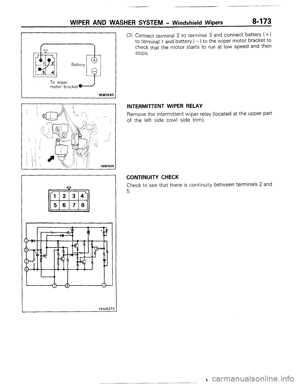
(3) Connect terminal 2 to terminal 3 and connect battery (+)
to terminal 1 and battery (-) to the wiper motor bracket to
check that the motor starts to run at low speed and then
stops.
INTERMITTENT WIPER RELAY
Remove the intermittent wiper relay (located at the upper part
of the left side cowl side trim).
CONTINUITY CHECK
Check to see that there is continuity between terminals 2 and
5.
) STB Revision
Page 194 of 284
a-174 WIPER AND WASHER $YSTEM - Windshield Wipers / Rear Wiper
REAR WIPtER
7
-est light
16K1920
t
REMOVAL AND INSTALLATION
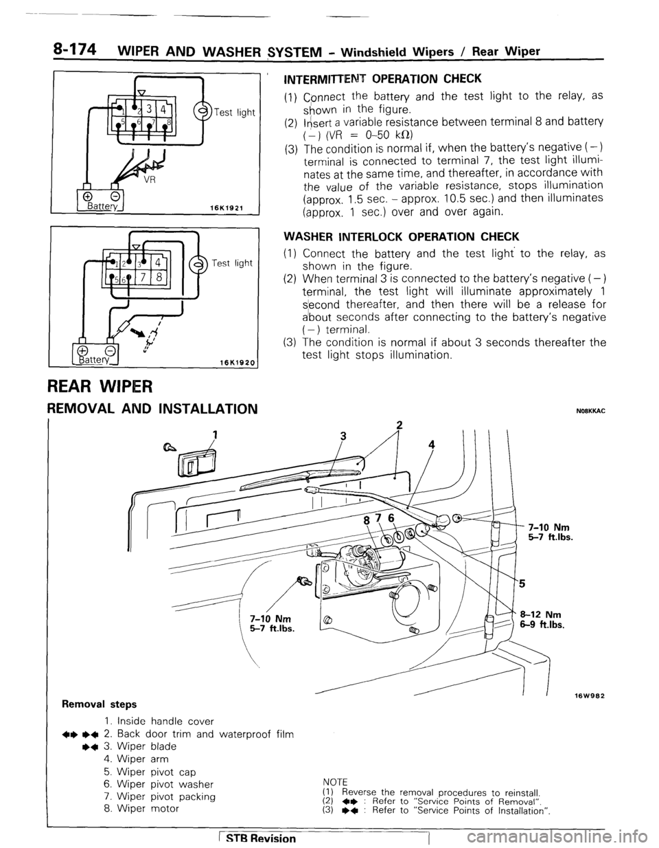
INTERMITTENT OPERATION CHECK
(1) Cpnnect the battery and the test light to the relay, as
shown in the figure.
(2) l&ert a variable resistance between terminal 8 and battery
(1) (VR = O-50 kfl)
(3) The condition is normal if, when the battery’s negative (-)
terminal is connected to terminal 7, the test light illumi-
nates at the same time, and thereafter, in accordance with
the value of the variable resistance, stops illumination
(approx. 1.5 sec. - approx. 10.5 sec.) and then illuminates
(approx. 1 sec.) over and over again.
WASHER INTERLOCK OPERATION CHECK
(1) Connect the battery and the test light’ to the relay, as
shown in the .figure.
(2) When terminal 3 is connected to the battery’s negative (-)
terminal, the test light will illuminate approximately 1
s’econd thereafter, and then there will be a release for
a’bout seconds after connecting to the battery’s negative
( - ) terminal.
The condition is normal if about 3 seconds thereafter the
test light stops illumination. (3
NOOKKAC
16W962
Removal steps
1. inside handle cover
+e l + 2. Back door trim and waterproof film
++ 3. Wiper blade
4. Wiper arm
5. Wiper pivot cap
6. Wiper pivot washer
7. Wiper pivot packing
8. Wiper motor NOTE
(1) Reverse the removal procedures to reinstall.
(2) 4* : Refer to “Service Points of Removal”. (3) l * : Refer to “Service Points of Installation”.
1 STB Revision
-7