service MITSUBISHI MONTERO 1987 1.G Owner's Manual
[x] Cancel search | Manufacturer: MITSUBISHI, Model Year: 1987, Model line: MONTERO, Model: MITSUBISHI MONTERO 1987 1.GPages: 284, PDF Size: 14.74 MB
Page 105 of 284
CHARGING SYSTEM - Alternator 8-85
SERVICE POINTS OF INSTALLATION
6. INSTALLATION OF ALTERNATOR
(1) Position the alternator and insert the support bolt. (Do not
attach the nut.)
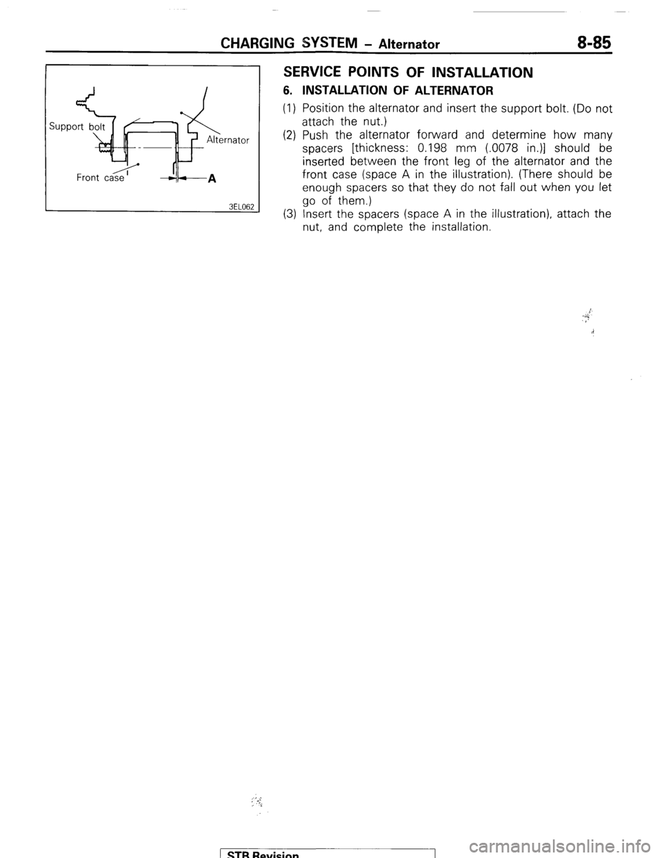
(2) Push the alternator forward and determine how many
spacers [thickness: 0.198 mm (.0078 in.)] should be
inserted between the front leg of the alternator and the
front case (space A in the illustration). (There should be
enough spacers so that they do not fall out when you let
go of them.)
(3) Insert the spacers (space A in the illustration), attach the
nut, and complete the installation.
; ‘.-:,
i
) STB Revision
Page 106 of 284
CHARGING SYSTEM-Alternator
10 11 14
8 ? \I I
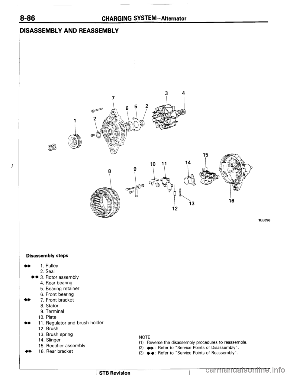
Disassembly steps
4* 1. Pulley
2. Seal
l a 3. Rotor assembly
4. Rear bearing
5. Bearing retainer
6. Front bearing
4*
7. Front bracket
8. Stator
9. Terminal
10. Plate
4* 11. Regulator and brush holder
12. Brush
13. Brush spring
14. Slinger
15. Rectifier assembly
4, 16. Rear bracket NOTE
(1) Reverse the disassembly procedures to reassemble.
(2) +e : Refer to “Service Points of Disassembly”.
(3) l
+ : Refer to “Service Points of Reassembly”.
1 EL666 1 STB Revision
Page 107 of 284
CHARGING SYSTEM-Alternator 8-87
6ELllt
SERVICE POINTS OF DISASSEMBLY
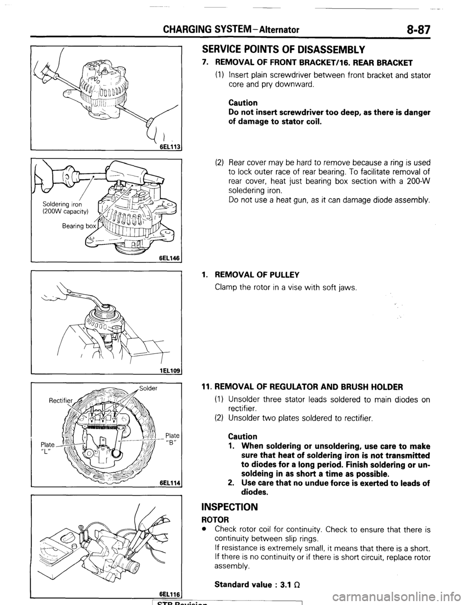
7. REMOVAL OF FRONT BRACKET/lG. REAR BRACKET
(1) Insert plain screwdriver between front bracket and stator
core and pry downward.
Caution
Do not insert screwdriver too deep, as there is danger
of damage to stator coil.
(2) Rear cover may be hard to remove because a ring is used
to lock outer race of rear bearing. To facilitate removal of
rear cover, heat just bearing box section with a 200-W
soledering iron.
Do not use a heat gun, as it can damage diode assembly.
1. REMOVAL OF PULLEY
Clamp the rotor in a vise with soft jaws.
11. REMOVAL OF REGULATOR AND BRUSH HOLDER
(1) Unsolder three stator leads soldered to main diodes on
rectifier.
(2) Unsolder two plates soldered to rectifier.
Caution
1. When soldering or unsoldering, use care to make
sure that heat of soldering iron is not transmitted
to diodes for a long period. Finish soldering or un-
soldeing in as short a time as possible.
2. Use care that no undue force is exerted to leads of
diodes.
INSPECTION
ROTOR
l Check rotor coil for continuity. Check to ensure that there is
continuity between slip rings.
If resistance is extremely small, it means that there is a short.
If there is no continuity or if there is short circuit, replace rotor
assembly.
Standard value : 3.1 f2
. . .
I 1 STB hewsion
Page 110 of 284
8-90 CHARGING SYSTEM-Alternator
Rear bracket Wire
6EL122
6EL123 I
SERVICE POINTS OF REASSEMBLY
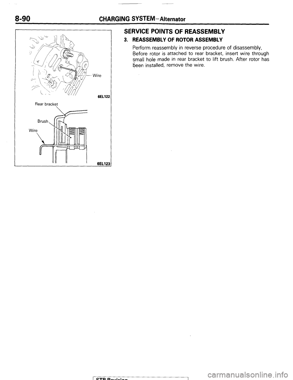
3. REASSEMBLY OF ROTOR ASSEMBLY
Perform reassembly in reverse procedure of disassembly,
Before
rotor is attached to rear bracket, insert wire through
small hole made in rear bracket to lift brush. After rotor has
6een installed, remove the wire.
STB Revision
Page 113 of 284
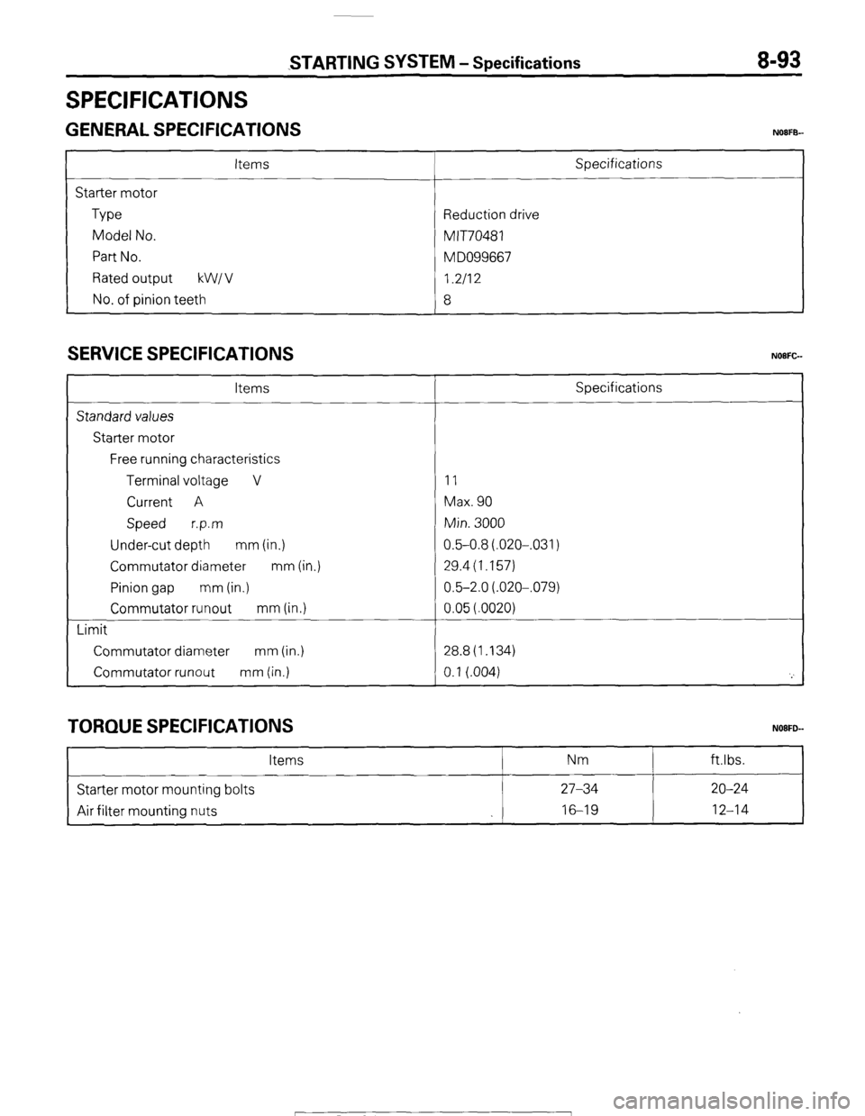
SPECIFICATIONS
STARTING SYSTEM - Specifications 8-93
GENERAL SPECIFICATIONS NOIFB-
Items
Starter motor
Type
Model No.
Part No.
Rated output kW1 v
No. of pinion teeth Specifications
Reduction drive
MIT70481
M DO99667
I.2112
8
SERVICE SPECIFICATIONS
Items
Standard values
Starter motor
Free running characteristics
Terminal voltage V
Current A
Speed r.p.m
Under-cut depth mm (in.)
Commutator diameter mm (in.)
Pinion gap mm (in.)
Commutator runout mm (in.)
Limit
Commutator diameter mm (in.)
Commutator runout mm (in.) Specifications
11
Max. 90
Min. 3000
0.5-0.8(.020-,031)
29.4(1.157)
0.5-2.0(.020-,079)
0.05(.0020)
28.8(1.134)
0.1 (.004)
'_'
TORQUE SPECIFICATIONS
Items Nm ftlbs.
Starter motor mounting bolts 27-34 20-24
Air filter mounting nuts 16-19
12-14
1 STB Revision
Page 117 of 284
STARTING WSTEM - Starter Motor 8-97
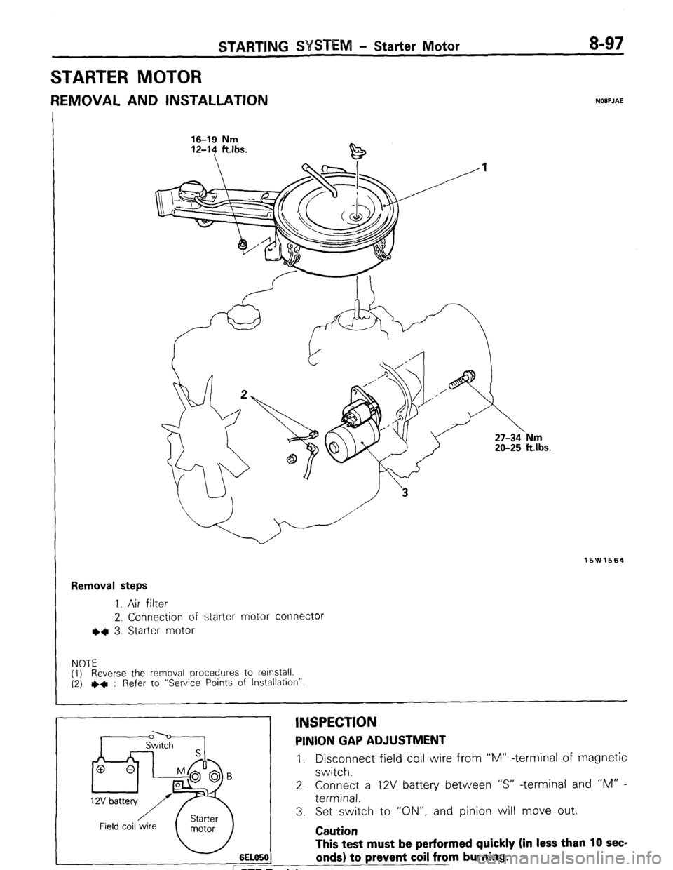
STARTER MOTOR
REMOVAL AND INSTALLATION NOBFJAE
16-19 Nm 16-19 Nm
12-l? ft.lbs. 12-14 ft.lbs.
15W1564
Removal steps
1. Air filter
2. Connection of starter motor connector
l * 3. Starter motor
NOTE
(1) Reverse the removal procedures to reinstall.
(2) ++ : Refer to “Service Points of Installation”
6EL05( This test must be performed quickly (in less than 10 sec-
onds) to prevent coil from burning. D Revision
INSPECTION PINION GAP ADJUSTMENT
I, Disconnect field coil wire from “M” -terminal of magnetic
switch.
2. Connect a 12V battery between “S” -terminal and “M” -
terminal.
3. Set switch to “ON”, and pinion will move out.
Caution
Page 119 of 284
WEEM -Starter Motor 8-99
I-
Carbon-pile rheostat
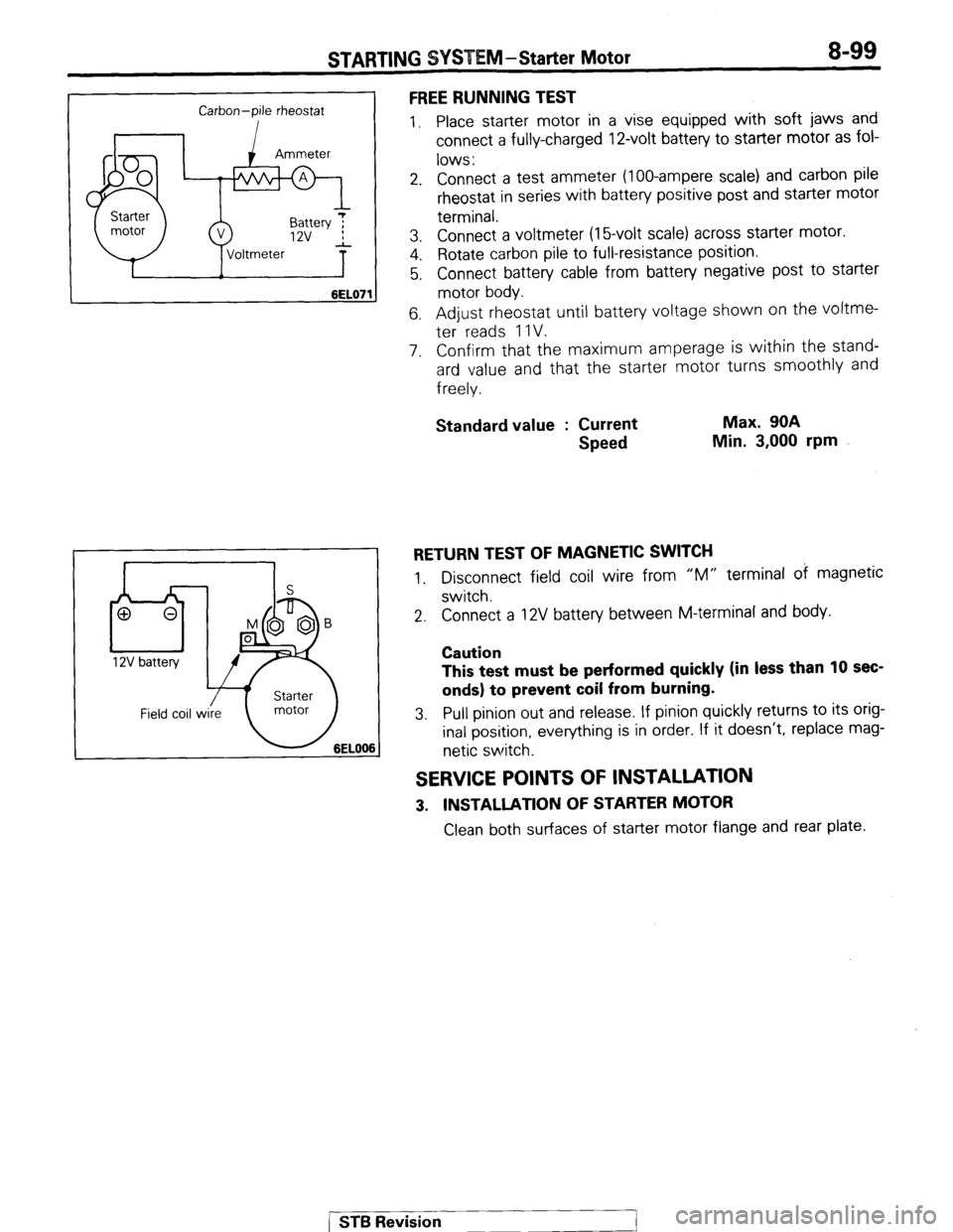
6EL07’ FREE RUNNING TEST
1. Place starter motor in a vise equipped with soft jaws and
connect a fully-charged 12-volt battery to starter motor as fol-
lows :
2. Connect a test ammeter (loo-ampere scale) and carbon pile
rheostat in series with battery positive post and starter motor
terminal.
3. Connect a voltmeter (16volt scale) across starter motor.
4. Rotate carbon pile to full-resistance position.
5. Connect battery cable from battery negative post to starter
motor body.
6. Adjust rheostat until battery voltage shown on the voltme-
ter reads 1 IV.
7. Confirm that the maximum amperage is within the stand-
ard value and that the starter motor turns smoothly and
freely.
Standard value : Current
Speed Max. 90A
Min. 3,000 rpm
RETURN TEST OF MAGNETIC SWITCH
1. Disconnect field coil wire from “M” terminal of magnetic
switch.
2. Connect a 12V battery between M-terminal and body.
Caution
This test must be performed quickly (in less than 10 sec-
onds) to prevent coil from burning.
3. Pull pinion out and release. If pinion quickly returns to its orig-
inal position, everything is in order. If it doesn’t, replace mag-
netic switch.
SERVICE POINTS OF INSTALLATION
3. INSTALLATlON OF STARTER MOTOR
Clean both surfaces of starter motor flange and rear plate.
[ ST6 Revision
1
Page 120 of 284
STARTING SYSTEM -Starter Motor
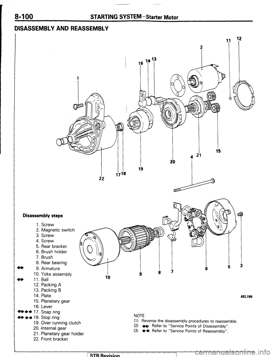
DISASSEMBLY AND REASSEMBLY
Disassembly steps
+* 1. Screw
2. Magnetic switch
3. Screw
4. Screw
5. Rear bracket
6. Brush holder
7. Brush
8. Rear bearing
9. Armature
10. Yoke assembly
4* 11. Ball
12. Packing A
13. Packing B
14. Plate
15. Planetary gear
16. Lever
+* l d 17. Snap ring
+* l a 18. Stop ring
19. Over running clutch
20. -Internal gear
21. Planetary gear holder
22. Front bracket
6ELlSS
NOTE
(1) Reverse the disassembly procedures to reassemble.
(2) a+: Refer to “Service Points of Disassembly”.
(3) l O: Refer to “Service Points of Reassembly”.
] STB Revision
Page 121 of 284
STARTING SYSTEM-Starter Motor 8-101
Snap
L Armature
1ELlO
pi-
SERVICE POINTS OF DISASSEMBLY
9. CAUTION OF ARMATURE/ll. BALL
When removing the armature, do not lose the ball which acts
as a bearing for the armature and tip.
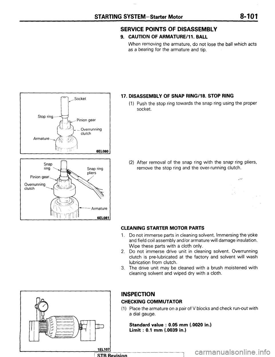
17. DISASSEMBLY OF SNAP RING/18. STOP RING
(1) Push the stop ring towards the snap ring using the proper
socket.
(2) After removal of the snap ring with the snap ring pliers,
remove the stop ring and the over-running clutch.
CLEANING STARTER MOTOR PARTS
1, Do not immerse parts in cleaning solvent. Immersing the yoke
and field coil assembly and/or armature will damage insulation.
Wipe these parts with a cloth only.
2. Do not immerse drive unit in cleaning solvent. Overrunning
clutch is pre-lubricated at the factory and solvent will wash
lubrication from clutch.
3. The drive unit may be cleaned with a brush moistened with
cleaning solvent and wiped dry with a cloth.
INSPECTION
CHECKING COMMUTATOR
(1) Place the armature on a pair of V blocks and check run-out with
a dial gauge.
Standard value : 0.05 mm (-0020 in.)
Limit : 0.1 mm (.0039 in.)
wision
I
Page 124 of 284
8-104 STARTING SYSTEM-Starter Motor
SERVICE POINTS OF REASSEMBLY
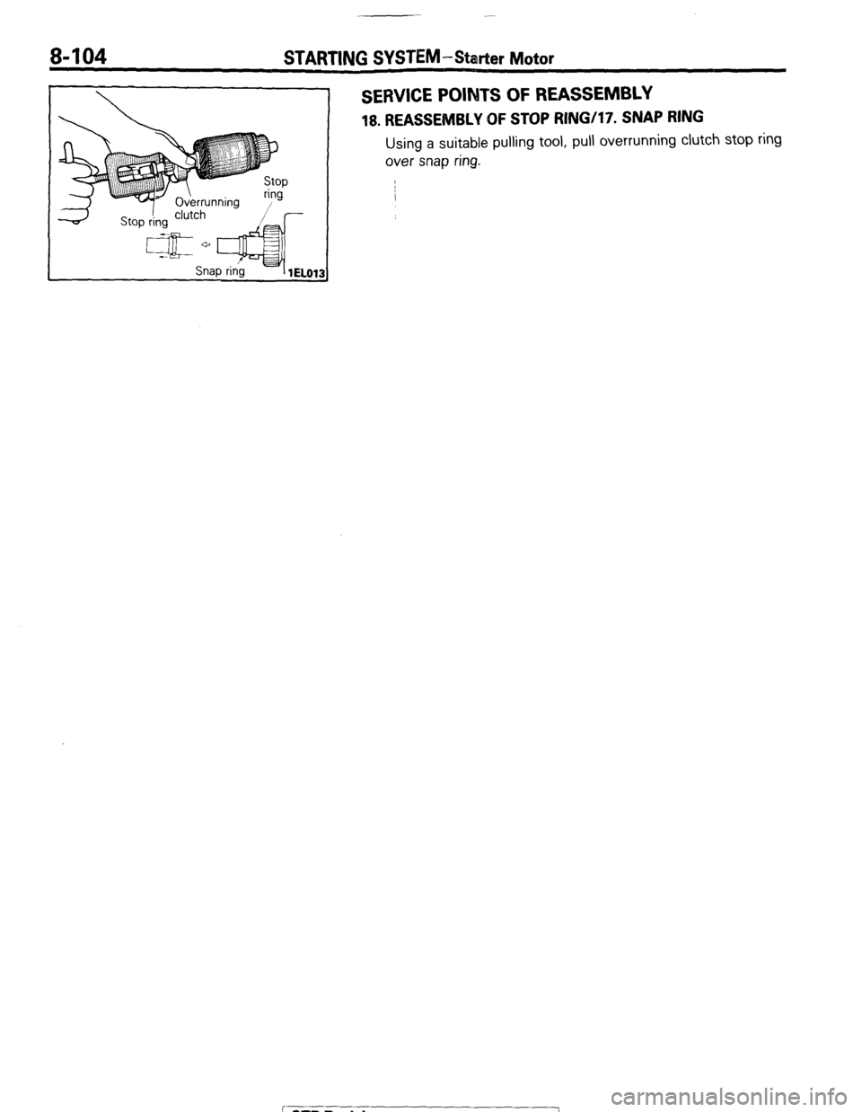
18. REASSEMBLY OF STOP RINGi17. SNAP RING
Using a suitable pulling tool, pull overrunning clutch stop ring
over snap ring.
1 STB Revision
--I