service MITSUBISHI MONTERO 1987 1.G Service Manual
[x] Cancel search | Manufacturer: MITSUBISHI, Model Year: 1987, Model line: MONTERO, Model: MITSUBISHI MONTERO 1987 1.GPages: 284, PDF Size: 14.74 MB
Page 150 of 284
8430 METERS AND GAUGES - Service Adjustment Procedures.
SERVICE BJUSTMENT. PROCEDURES
SPEEDOMETER INSPECTION NOSHIAA
I. Adjust tire inflation pressure to the standard value. (Refer
to’GROUP 22 WHEELS AND TIRES-General Specifications)
2. Use speedometer tester to make sure that the speedome-
ter indication error is within the standard value.
Standard value :
Meter with “km/h” indication km/h
20 km/h +4
-1
40 km/h +4
0
80 km/h +5
0
120 km/h + 5.5
+0.5
Meter with “mph” indication
mph
10 mph
25 mph
50 mph
75 mph +I.5
21.5
+I.5
&I.5
Caution
1 When using a speedometer tester to inspect the
speedometer, be sure to chock the non-drive wheels
to prevent the vehicle from moving. Also be sure to
set the transfer shift lever to “2H”.
2 If there is a special regulation for speedometer
indication error in the area where the ‘vehicle is
operated, be sure to meet the requirement of the
regulation.
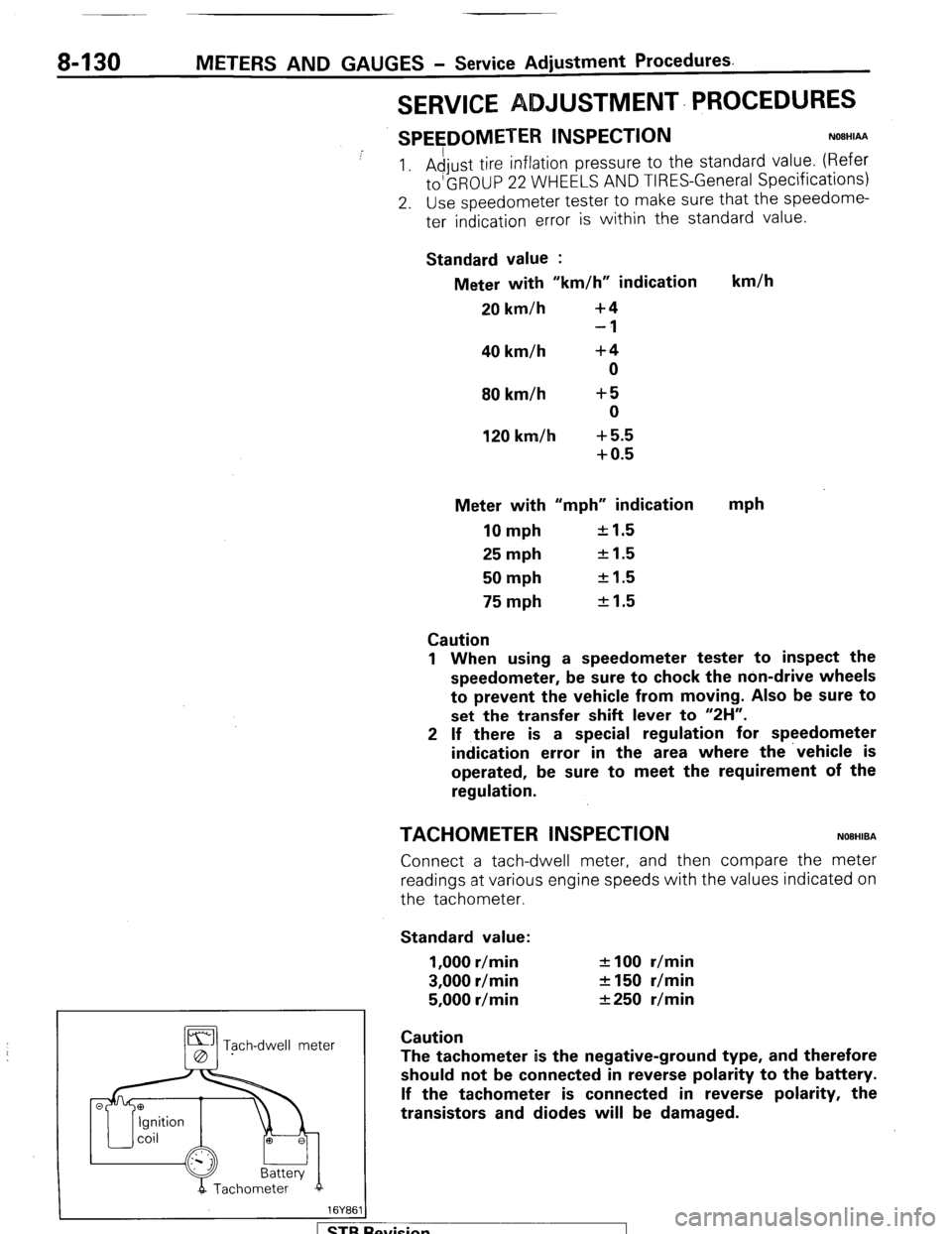
TACHOMETER INSPECTION NOBHIBA
Connect a tach-dwell meter, and then compare the meter
readings at various engine speeds with the values indicated on
the tachometer.
Standard value:
1,000 r/min
3,000 r/min
5,000 r/min f 100 r/min
2150 r/min
&250 r/min
Tgch-dwell meter Caution
The tachometer is the negative-ground type, and therefore
should not be connected in reverse polarity to the battery.
If the tachometer is connected in reverse polarity, the
transistors and diodes will be damaged.
evision
Page 151 of 284
METERS AND GAUGES - Service Adiustment Procedures 8-131
r
(harness side) 16W834
Stopper (upper)
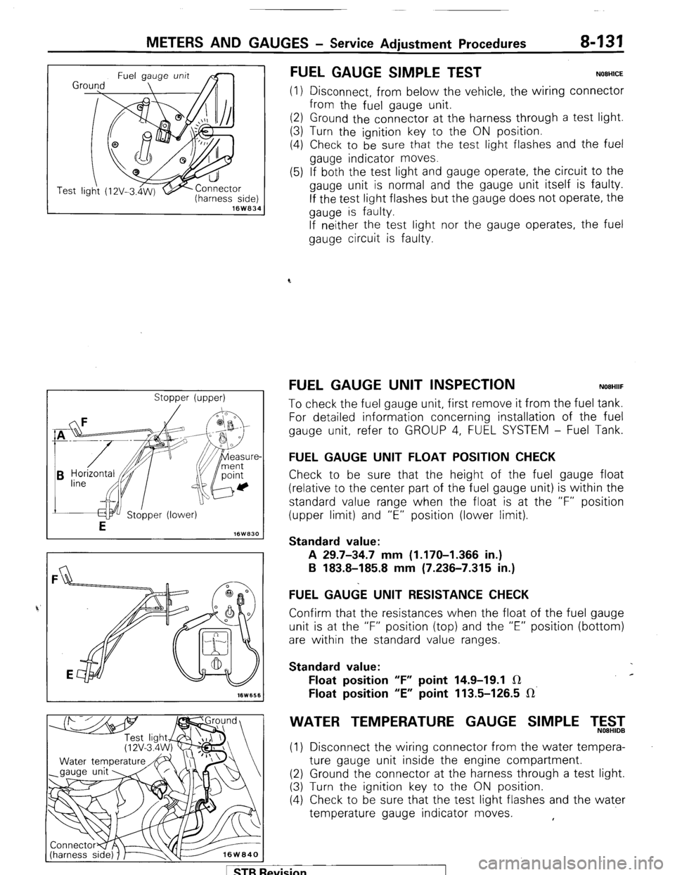
FUEL GAUGE SIMPLE TEST NOEHICE
(1) Disconnect, from below the vehicle, the wiring connector
from the fuel gauge unit.
(2) Ground the connector at the harness through a test light.
(3) Turn the ignition key to the ON position.
(4) Check to be
sure that the test light flashes and the fuel
gauge indicator moves.
(5) If both the test light and gauge operate, the circuit to the
gauge unit is normal and the gauge unit itself is faulty.
If the test light flashes but the gauge does not operate, the
gauge is faulty.
If neither the test light nor the gauge operates, the fuel
gauge circuit is faulty.
FUEL GAUGE UNIT INSPECTION NOEHIIF
To check the fuel gauge unit, first remove it from the fuel tank.
For detailed information concerning installation of the fuel
gauge unit, refer to GROUP 4, FUEL SYSTEM - Fuel Tank.
FUEL GAUGE UNIT FLOAT POSITION CHECK
Check to be sure that the height of the fuel gauge float
(relative to the center part of the fuel gauge unit) is within the
standard value range when the float is at the “F” position
(upper limit) and “E” position (lower limit).
Standard value:
A 29.7-34.7 mm (1.170-I .366 in.)
B 183.8-185.8 mm (7.236-7.315 in.)
FUEL GA&E UNIT RESISTANCE CHECK
Confirm that the resistances when the float of the fuel gauge
unit is at the “F” position (top) and the “E” position (bottom)
are within the standard value ranges.
Standard value:
Float position “F” point 14.9-19.1 IR c
Float position “E” point 113.5-126.5 IR’
WATER TEMPERATURE GAUGE SIMPLE T,5$2
(1) Disconnect the wiring connector from the water tempera-
ture gauge unit inside the engine compartment.
(2) Ground the connector at the harness through a test light.
(3) Turn the ignition key to the ON position.
(4) Check to be sure that the test light flashes and the water
temperature gauge indicator moves. ,
1 STB Revision
Page 152 of 284
8-132 METERS AND GAUGES - Service Adjustment Procedures
(5) If both the test light and gauge operate, the circuit to the
gauge unit is normal and the gauge unit itself is faulty.
If the test light flashes but the gauge does not operate, the
gauge is faulty.
If 1 neither the test light nor the gauge operates, the water
temperature gauge circuit is faulty.
Se
VVATER TEMPERATURE GAUGE UNIT ONSPEC-
TION
NOBHIKD
To check the water temperature gauge unit, first remove it
from the intake manifold.
For detailed information concerning installation of the water
temperature gauge unit, refer to GROUP 11, INTAKE AND
EXHAUST SYSTEM - Intake Manifold.
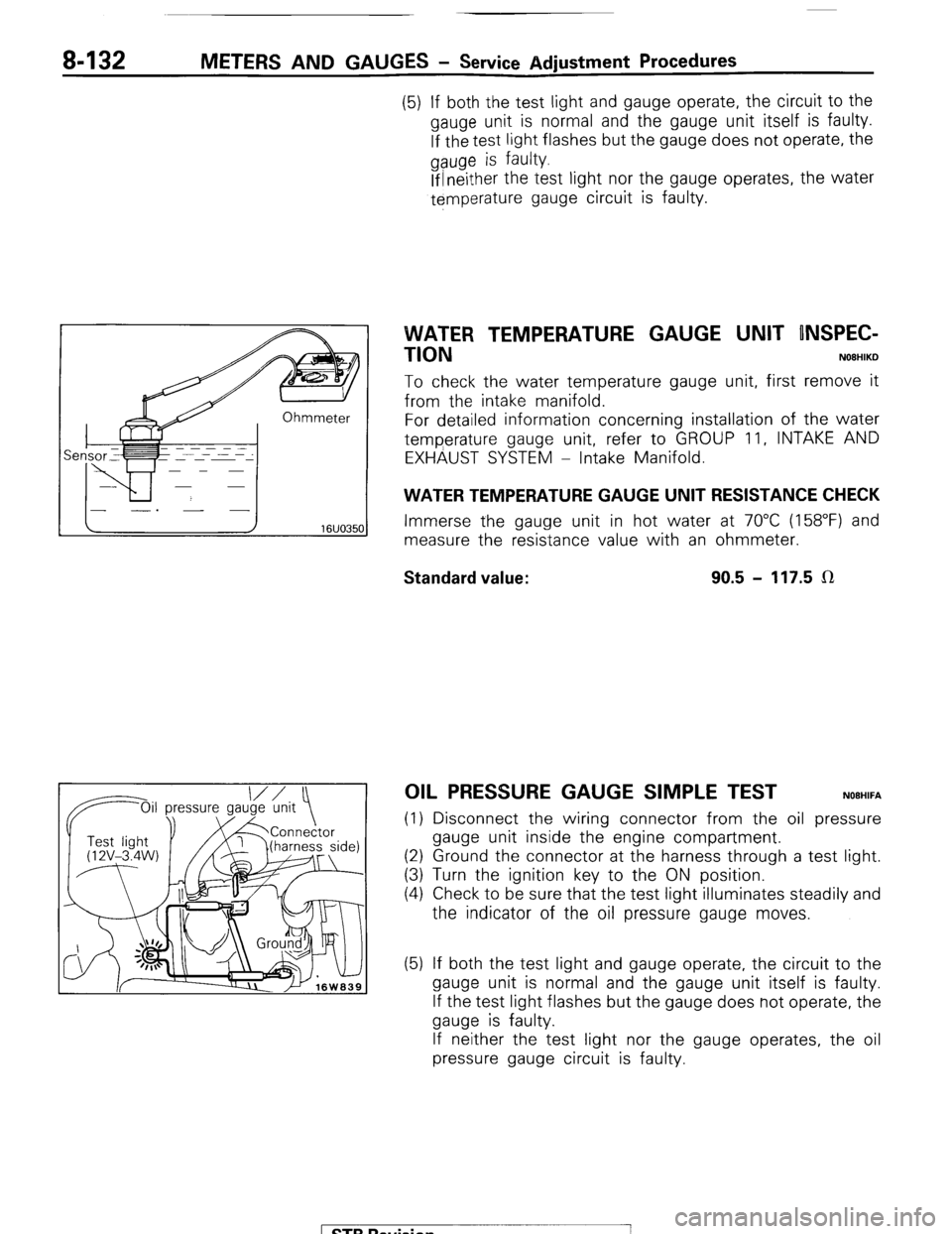
WATER TEMPERATURE GAUGE UNIT RESISTANCE CHECK
Immerse the gauge unit in hot water at 70°C (158°F) and
measure the resistance value with an ohmmeter.
Standard value: 90.5 - 117.5 LR
OIL PRESSURE GAUGE SIMPLE TEST NOEHIFA
(1) Disconnect the wiring connector from the oil pressure
gauge unit inside the engine compartment.
(2) Ground the connector at the harness through a test light.
(3) Turn the ignition key to the ON position.
(4) Check to be sure that the test light illuminates steadily and
the indicator of the oil pressure gauge moves.
(5) If both the test light and gauge operate, the circuit to the
gauge unit is normal and the gauge unit itself is faulty.
If the test light flashes but the gauge does not operate, the
gauge is faulty.
If neither the test light nor the gauge operates, the oil
pressure gauge circuit is faulty.
1 STB Revision
-7
Page 153 of 284
METERS AND GAUGES - Service Adjustment Procedures 8-133
IOil p Oil pressure ressure
gauge unit
1 I Test light
‘@‘(12V - 3.4 I
W)
16W1576
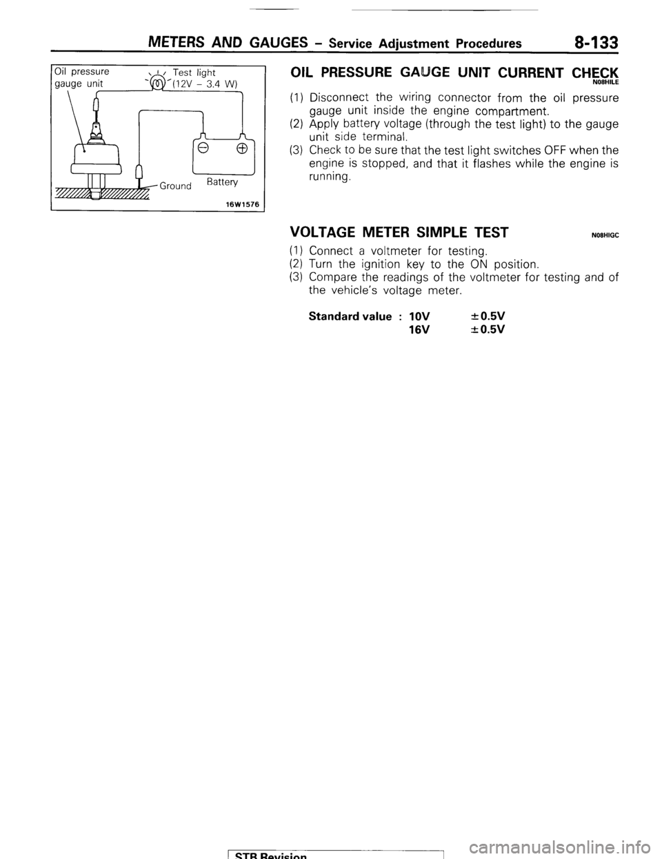
OIL PRESSURE GA GE UNIT CURRENT CHEC,‘l<,
(1) Disconnect the wiring connector from the oil pressure
gauge unit inside the engine compartment.
(2) Apply battery voltage (through the test light) to the gauge
unit side terminal.
(3) Check to be sure that the test light switches OFF when the
engine is stopped, and that it flashes while the engine is
running.
VOLTAGE METER SIMPLE TEST NOEHIGC
(1) Connect a voltmeter for testing.
(2) Turn the ignition key to the ON position.
(3) Compare the readings of the voltmeter for testing and of
the vehicle’s voltage meter. Standard value : 1OV
16V + 0.5v
+ 0.5v
1 STB Revision
Page 154 of 284
8-134 METERS AND GAUGES - Combination Meter
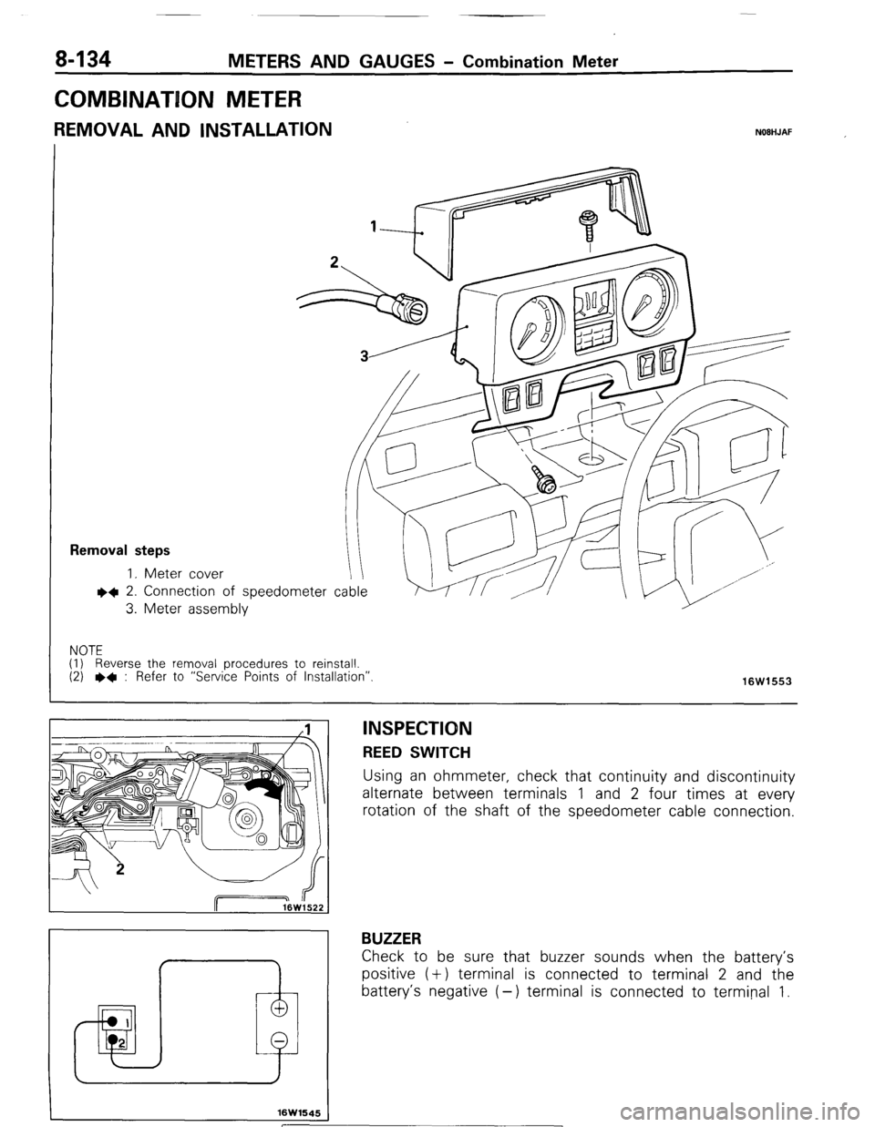
COMBINATION METER
REMOVAL AND INSTALLATION NOBHJAF
Removal steps
1. Meter cover
l 4 2. Connection
3. Meter asset of speedometer cable
nbly
NOTE
(I) Reverse the removal procedures to reinstall.
(2)
l + : Refer to “Service Points of Installation”.
16W1553
I 1 I
I
f
16W1645
INSPECTION REED SWITCH
Using an ohmmeter, check that continuity and discontinuity
alternate between terminals 1 and 2 four times at every
rotation of the shaft of the speedometer cable connection.
BUZZER
Check to be sure that buzzer sounds when the battery’s
positive (+) terminal is connected to terminal 2 and the
battery’s negative (-) terminal is connected to terminal 1.
[ STB Revision
Page 155 of 284
METERS AND GAUGES - Combination Meter 8-135
.3
16WQ25
16W925
10W926
16F554
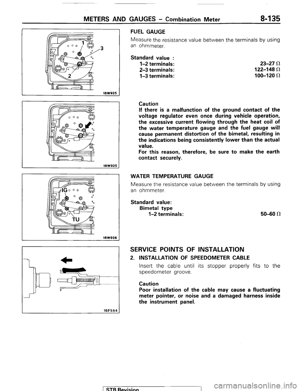
FUEL GAUGE
Measure the resistance value between t.he terminals by using
an ohmmeter.
Standard value :
l-2 terminals:
2-3 terminals:
l-3 terminals: 23-27 R
122-148 Sz
100-120 IR
Caution
If there is a malfunction of the ground contact of the
voltage regulator even once during vehicle operation,
the excessive current flowing through the heat coil of
the water temperature gauge and the fuel gauge will
cause permanent distortion of the bimetal, resulting in
the indications being consistently lower than the actual
value.
For this reason, therefore, be sure to make the earth
contact securely.
WATER TEMPERATURE GAUGE
Measure the resistance value between the terminals by using
an ohmmeter.
Standard value:
Bimetal type
l-2 terminals: 50-80 n
SERVICE POINTS OF INSTALLATION
2. INSTALLATION OF SPEEDOMETER CABLE
Insert the cable until its stopper properly fits to the
speedometer groove.
Caution
Poor installation of the cable may cause a fluctuating
meter pointer, or noise and a damaged harness inside
the instrument panel.
) STB Revision
Page 164 of 284
8-144
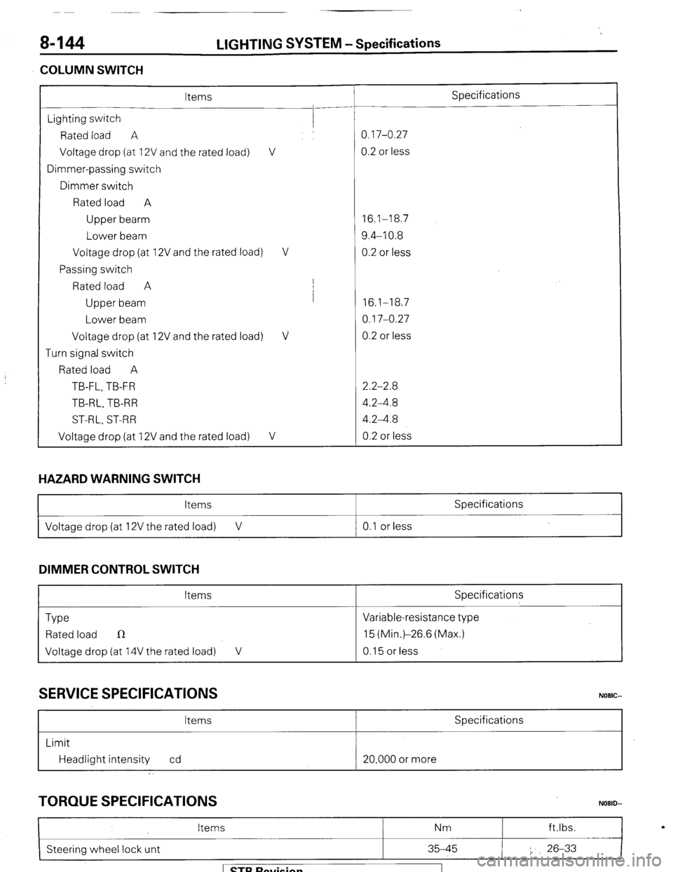
COLUMN SWITCH LIGHTING
SYSTEM -Specifications
Items Specifications
Lighting switch
Rated load A 0.17-0.27
Voltage drop (at 12V and the rated load) V 0.2 or less
Dimmer-passing switch
Dimmer switch
Rated load A
Upper bearm 16.1-18.7
Lower beam 9.4-10.8
Voltage drop (at 12V and the rated load) V 0.2 or less
Passing switch
Rated load A I
Upper beam I
16.1-18.7
Lower beam 0.17-0.27
Voltage drop (at 12V and the rated load)
V 0.2 or less
Turn signal switch
Rated load A
TB-FL, TB-FR 2.2-2.8
TB-RL, TB-R R 4.2-4.8
ST-RL, ST-RR 4.2-4.8
Voltage drop (at 12V and the rated load)
V 0.2 or less
HAZARD WARNING SWITCH
Items Specifications
I Voltage drop (at 12V the rated load) V 0.1 or less
I
DIMMER CONTROL SWITCH
Items Specifications
Type Variable-resistance type
Rated load n 15 (Min.)-26.6 (Max.)
Voltage drop (at 14V the rated load) V 0.15 or less
SERVICE SPECIFICATIONS
Items Specifications
Limit
Headlight intensity cd 20,000 or more
TORQUE SPECIFICATIONS
I
Items Nm ft.lbs.
N08lb
Steering wheel lock unt 35-45 I. 26-33
I
1 STB Revision
Page 177 of 284
LIGHTING SYSTEM - Service Adjustment Procedures 8-157
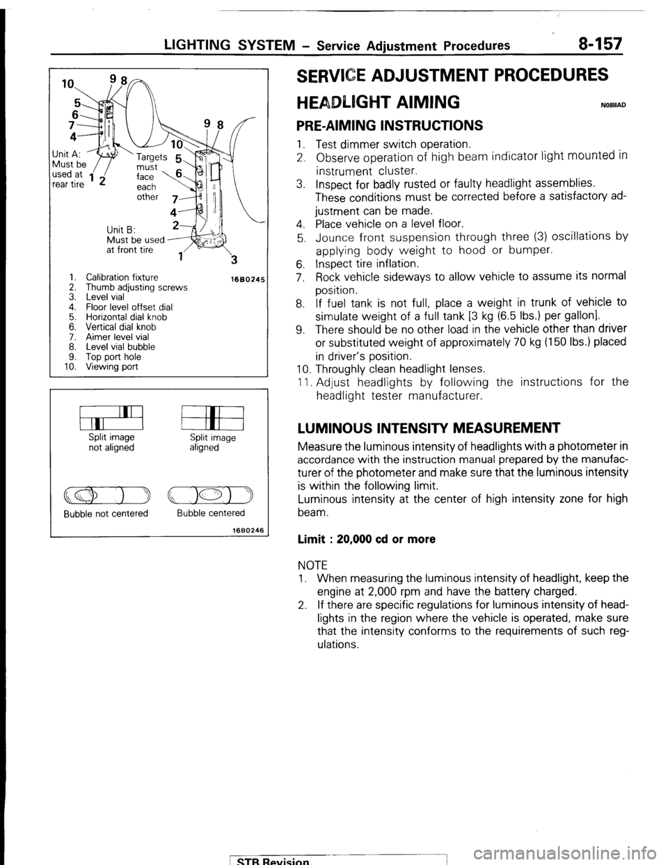
Must be used J;it A:
I ‘w ‘Targets
1. Calibration fixture
2. Thumb adjusting screws
3. Level vial
4. Floor level offset dial
5. Horizontal dial knob
6. Vertical dial knob
7. Aimer level vial
8. Level vial bubble
9. Top port hole
10. Viewing port
1660245
Split image
not aligned Split image
aligned
Bubble not centered Bubble centered
1660246
E ADJUSTMENT PROCEDURES
T AIMING
PRE-AIMING INSTRUCTIONS 1. Test dimmer switch operation.
2. Observe operation of high beam indicator light
mounted in instrument cluster.
3. Inspect for badly rusted or faulty headlight assemblies.
These conditions must be corrected before a satisfactory ad-
justment can be made.
4. Place vehicle on a level floor.
5. Jounce front suspension through three (3) oscillations by
applying body weight to hood or bumper.
6. Inspect tire inflation.
7. Rock vehicle sideways to allow vehicle to assume its normal
position.
8. If fuel tank is not full, place a weight in trunk of vehicle to
simulate weight of a full tank [3 kg (6.5 Ibs.) per gallon].
9. There should be no other load in the vehicle other than driver
or substituted weight of approximately 70 kg (150 Ibs.) placed
in driver’s position.
10. Throughly clean headlight lenses.
11. Adjust headlights by following the instructions for the
headlight tester manufacturer.
LUMINOUS INTENSITY MEASUREMENT Measure the luminous intensity of headlights with a photometer in
accordance with the instruction manual prepared by the manufac-
turer of the photometer and make sure that the luminous intensity
is within the following limit.
Luminous intensity at the center of high intensity zone for high
beam.
Limit : 20,000 cd or more NOTE
1. When measuring the luminous intensity of headlight, keep the
engine at 2,000 rpm and have the battery charged.
2. If there are specific regulations for luminous intensity of head-
lights in the region where the vehicle is operated, make sure
that the intensity conforms to the requirements of such reg-
ulations.
pTB Revision
Page 179 of 284
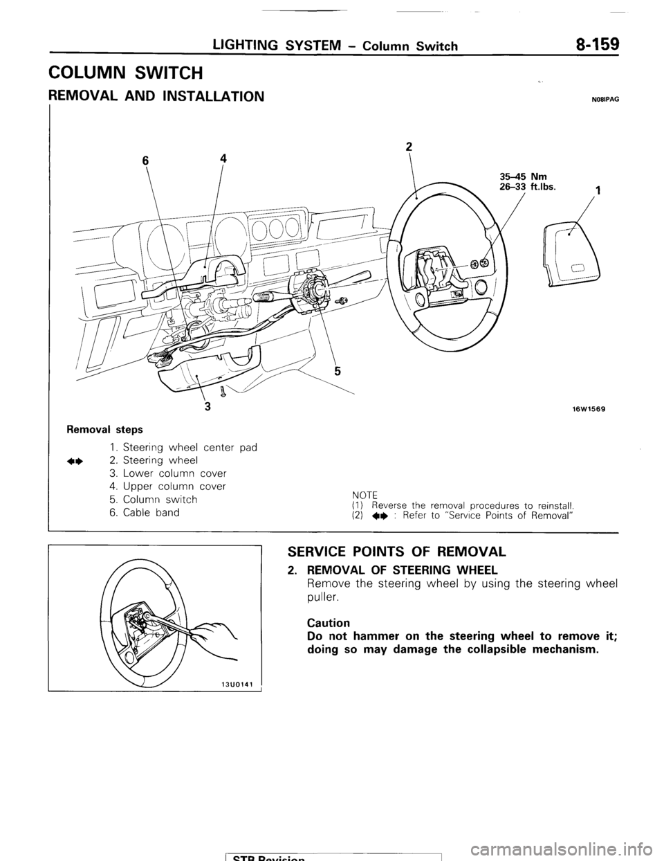
LIGHTING SYSTEM - Column Switch 8-159
COLUMN SWITCH
REMOVAL AND INSTALLATION NOBIPAG
3
Removal steps
I. Steering wheel center pad
*I) 2. Steering wheel
3. Lower column cover
4. Upper column cover
hlnTC
16W1569
5. Column switch
6. Cable band I\I”IC (I) Reverse the removal procedures to reinstall.
(2) l * : Refer to “Service Points of Removal”
SERVICE POINTS OF REMOVAL 2. REMOVAL OF STEERING WHEEL
Remove the steering wheel by using the steering wheel
puller. Caution
Do not hammer on the steering wheel to remove it;
doing so may damage the collapsible mechanism.
) STB Revision
Page 190 of 284
8-170 WIPER AND WASHER SYSTEM - Service Adjustment Procedures
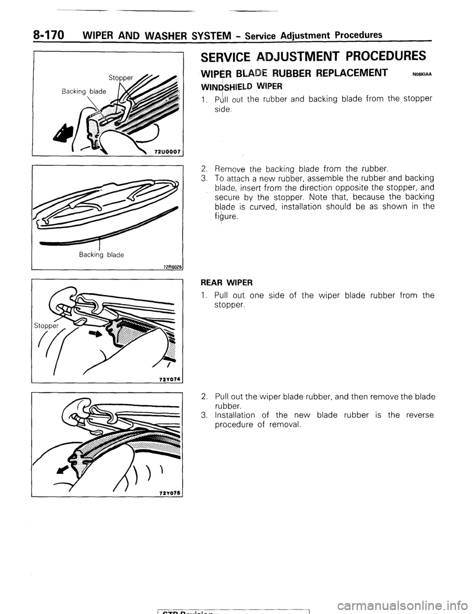
SERVICE ADJUSTMENT PROCEDURES
WIPE#l BLADE RUBBER REPLACEMENT
WINdSHIELD WIPER
NOBKIAA
1. Pull out the rubber and backing blade from the stopper
side.
Back&g blade
2. Remove the backing blade from the rubber.
3. To attach a new rubber, assemble the rubber and backing
blade, insert from the direction opposite the stopper, and
secure by the stopper. Note that, because the backing
blade is curved, installation should be as shown in the
figure.
REAR WIPER
1. Pull out one side of the wiper blade rubber from the
stopper.
2. Pull out the wiper blade rubber, and then remove the blade
rubber.
3. Installation of the new blade rubber is the reverse
procedure of removal.
( ST6 Revision