service MITSUBISHI MONTERO 1987 1.G Repair Manual
[x] Cancel search | Manufacturer: MITSUBISHI, Model Year: 1987, Model line: MONTERO, Model: MITSUBISHI MONTERO 1987 1.GPages: 284, PDF Size: 14.74 MB
Page 191 of 284
WIPER AND WASHER SYSTEM - Windshield Wipers 8-171
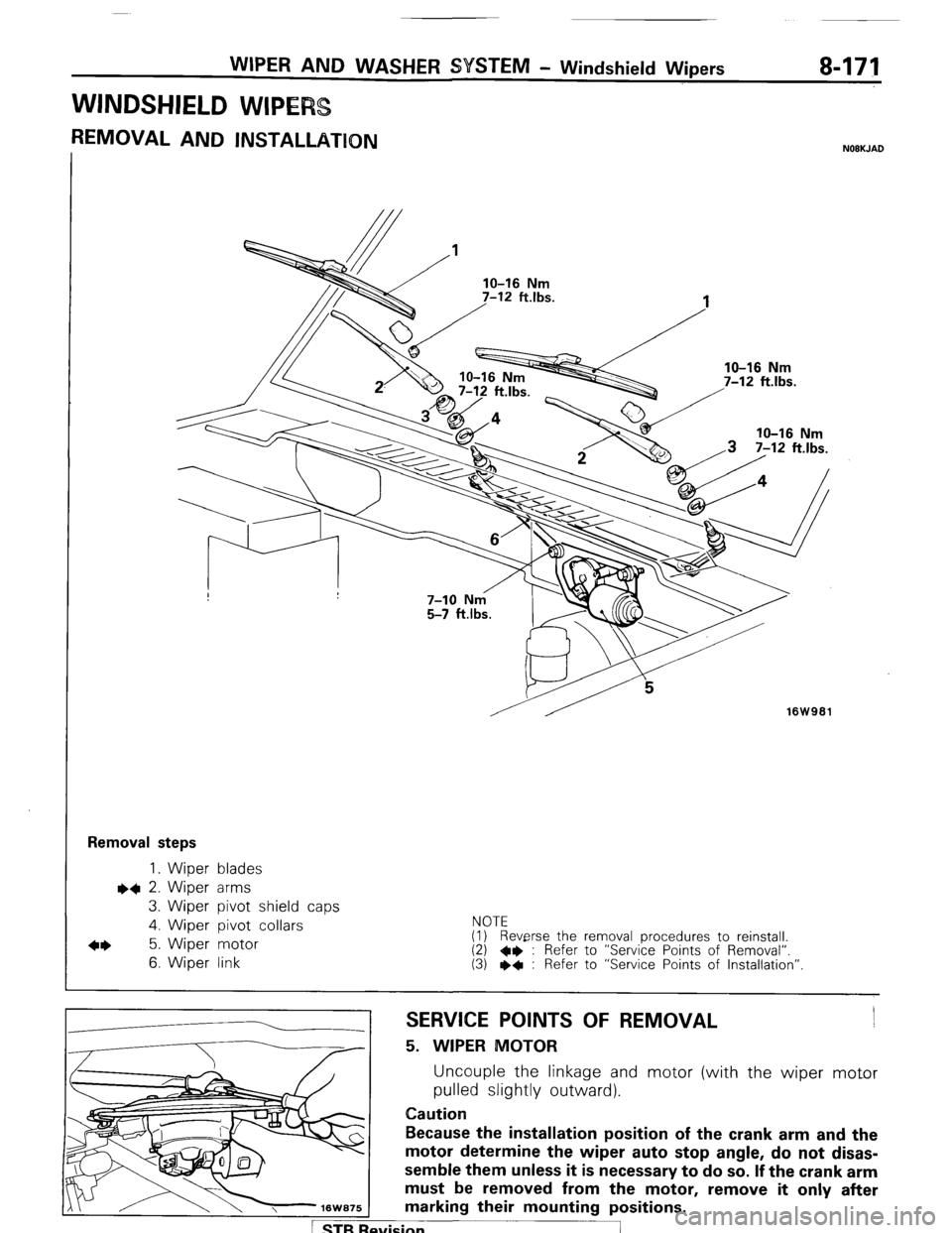
WINDSHIELD WIPE
REMOVAL AND INSTALLATION NOBKJAD
16W961
Removal steps
1. Wiper blades l
+ 2. Wiper arms
3. Wiper pivot shield caps
4. Wiber pivot collars NOTE
4* 5. Wiper motor (1) Reverse the removal procedures to reinstall.
6. Wiper link (2) 4* : Refer to “Service Points of Removal”.
(3) I)* : Refer to “Service Points of Installation”
SERVICE POINTS OF REMOVAL
5. WIPER MOTOR
Uncouple the linkage and motor (with the wiper motor
pulled slightly outward).
Caution
Because the installation position of the crank arm and the
motor determine the wiper auto stop angle, do not disas-
semble them unless it is necessary to do so. If the crank arm
must be removed from the motor, remove it only after
marking their mounting positions.
svision
I
Page 192 of 284
8-172 WIPER AND WAsHER SYSTEM - Windshield Wipers
nm (in.1 16Y1568 I
I
J (v L
I 2
Battery
II I , +
Battery @
16W1538
bv
J’ L
.jr 2.
Battery
3 4
I
16W1539
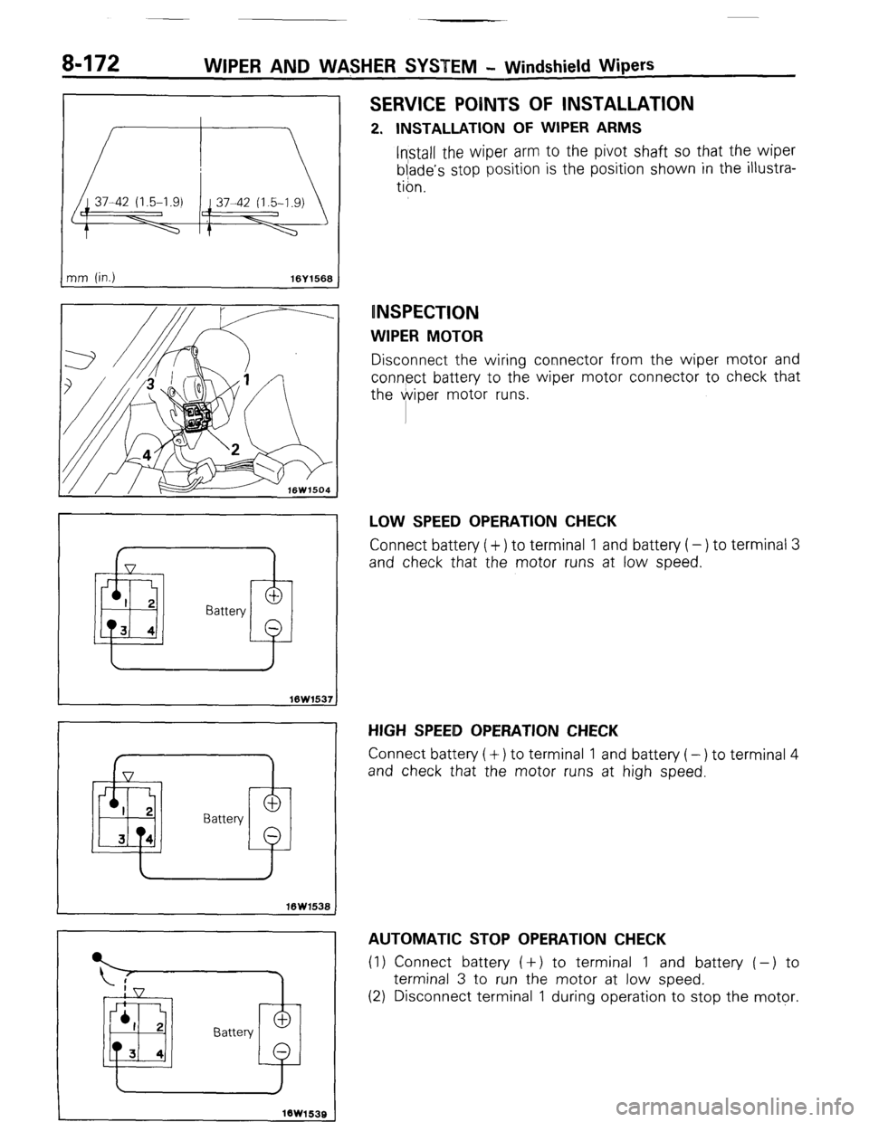
SERVICE POINTS OF INSTALLATION
2. INSTALLATION OF WIPER ARMS
Install the wiper arm to the pivot shaft so that the wiper
blade’s stop position is the position shown in the illustra-
tion.
INSPECTION
WIPER MOTOR
Disconnect the wiring connector from the wiper motor and
connect battery to the wiper motor connector to check that
the @viper motor runs.
LOW SPEED OPERATION CHECK
Connect battery ( + ) to terminal 1 and battery ( - ) to terminal 3
and check that the motor runs at low speed.
HIGH SPEEID OPERATION CHECK
Connect battery (+) to terminal 1 and battery (-) to terminal 4
and check that the motor runs at high speed.
AUTOMATIC STOP OPERATION CHECK
(1) Connect battery ( +) to terminal 1 and battery ( -) to
terminal 3 to run the motor at low speed.
(2) Disconnect terminal 1 during operation to stop the motor.
1 STB Revision
-7
Page 194 of 284
a-174 WIPER AND WASHER $YSTEM - Windshield Wipers / Rear Wiper
REAR WIPtER
7
-est light
16K1920
t
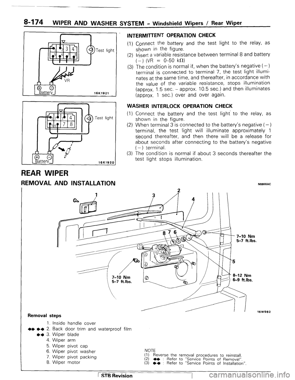
REMOVAL AND INSTALLATION
INTERMITTENT OPERATION CHECK
(1) Cpnnect the battery and the test light to the relay, as
shown in the figure.
(2) l&ert a variable resistance between terminal 8 and battery
(1) (VR = O-50 kfl)
(3) The condition is normal if, when the battery’s negative (-)
terminal is connected to terminal 7, the test light illumi-
nates at the same time, and thereafter, in accordance with
the value of the variable resistance, stops illumination
(approx. 1.5 sec. - approx. 10.5 sec.) and then illuminates
(approx. 1 sec.) over and over again.
WASHER INTERLOCK OPERATION CHECK
(1) Connect the battery and the test light’ to the relay, as
shown in the .figure.
(2) When terminal 3 is connected to the battery’s negative (-)
terminal, the test light will illuminate approximately 1
s’econd thereafter, and then there will be a release for
a’bout seconds after connecting to the battery’s negative
( - ) terminal.
The condition is normal if about 3 seconds thereafter the
test light stops illumination. (3
NOOKKAC
16W962
Removal steps
1. inside handle cover
+e l + 2. Back door trim and waterproof film
++ 3. Wiper blade
4. Wiper arm
5. Wiper pivot cap
6. Wiper pivot washer
7. Wiper pivot packing
8. Wiper motor NOTE
(1) Reverse the removal procedures to reinstall.
(2) 4* : Refer to “Service Points of Removal”. (3) l * : Refer to “Service Points of Installation”.
1 STB Revision
-7
Page 195 of 284
WIPER AND WASHER SYSTEM - Rear Wiper 8-175
SERVICE POINTS OF REMOVAL
2. REMOVAL OF BACK DOOR TRIM AND WATERPROOF
FILM
Refer to GROUP 23 BODY - Back Door Trim and Water-
proof Film.
I 16K394 1
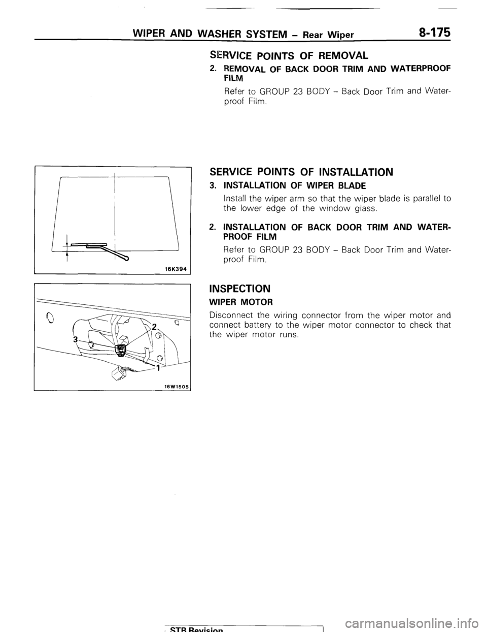
SERVICE POINTS OF INSTALLATION
3. INSTALLATION OF WIPER BLADE
Install the wiper arm so that the wiper blade is parallel to
the lower edge of the window glass.
2. INSTALLATION OF BACK DOOR TRIM AND WATER-
PROOF FILM
Refer to GROUP 23 BODY - Back Door Trim and Water-
proof Film.
INSPECTION
WIPER MOTOR
Disconnect the wiring connector from the wiper motor and
connect battery to the wiper motor connector to check that
the wiper motor runs.
I STB Revision
Page 198 of 284
8-178 WIPER AND WASHER SYSTEM - Rear Washer
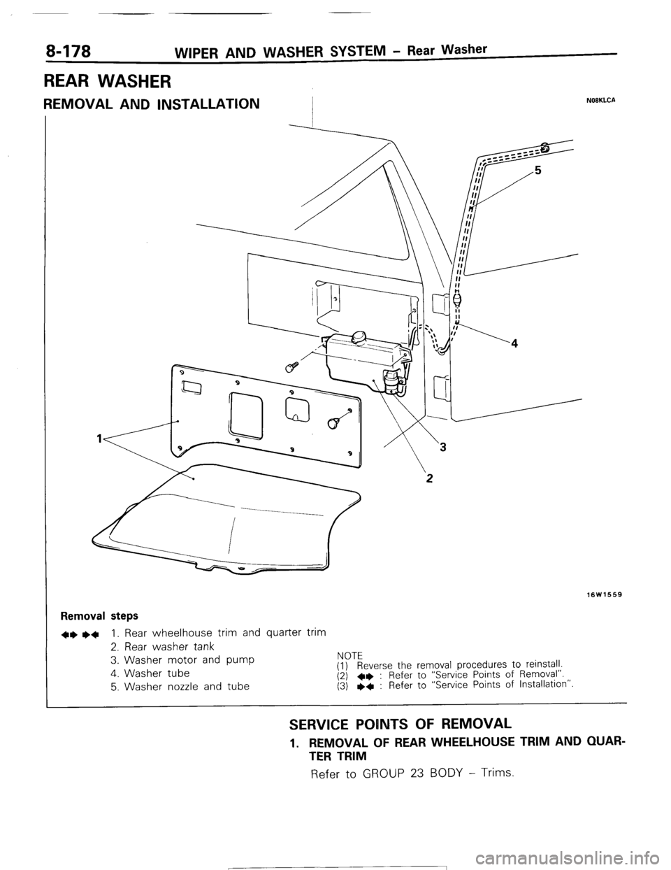
REAR WASHER
REMOVAL AND INSTALLATION I N08KLCA
16W1669
Removal steps
+e ~~ 1. Rear wheelhouse trim and quarter trim
2. Rear washer tank
3. Washer motor and pump NOTE
4. Washer tube
(1) Reverse the removal procedures to reinstall.
(2) l * : Refer to “Service Points of Removal”. 5. Washer nozzle and tube (3) l + : Refer to “Service Points of Installation”.
SERVICE POINTS OF REMOVAL
1. REMOVAL OF REAR WHEELHOUSE TRIM AND QUAR-
TER TRIM Refer to
GROUP 23 BODY - Trims.
1 STR Ravisinn -7
Page 199 of 284
I 1
+ -
li.if 1
2
WIPER AND WASHER SYSTEM - Rear Washer / Headlight Washer 8-179 (1) Check to be sure that there is washer fluid in the washer
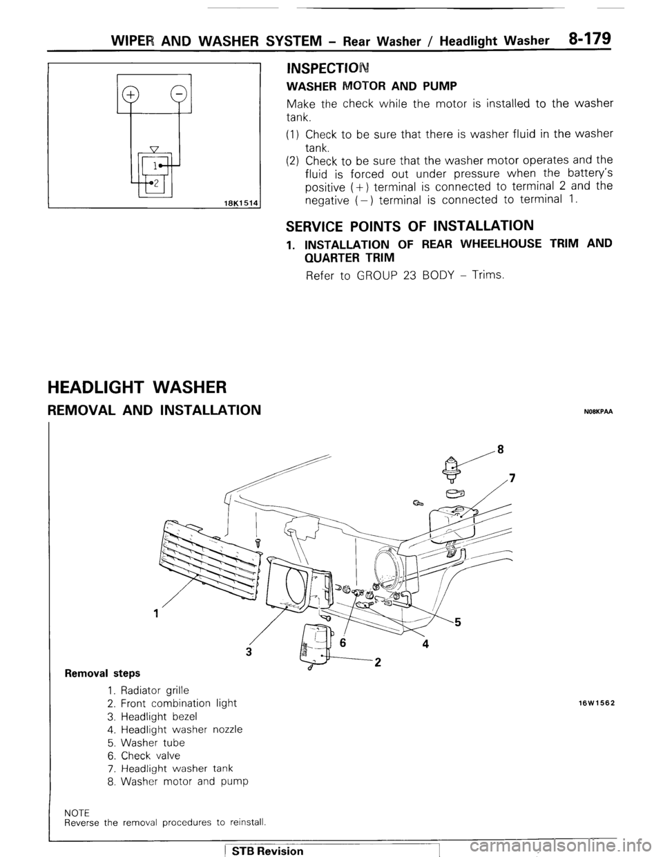
tank.
(2) Check to be sure that the washer motor operates and the
fluid is forced out under pressure when the battery’s
positive (+) terminal is connected to terminal 2 and the
negative (-) terminal is connected to terminal 1.
INSPECTION
WASHER MOTOR AND PUMP Make the check while the motor is installed to the washer
tank.
SERVICE POINTS OF INSTALLATION
1. INSTALLATION OF REAR WHEELHOUSE TRIM AND
QUARTER TRIM Refer to GROUP 23 BODY - Trims.
HEADLIGHT WASHER
REMOVAL AND INSTALLATION NOEKPAA
Removal steps 1. Radiator grille
2. Front combination light
3. Headlight bezel
4. Headlight washer nozzle
5. Washer tube
6. Check valve
7. Headlight washer tank
8. Washer motor and pump
16W1562
NOTE Reverse the removal procedures to reinstall.
) STB Revision
Page 201 of 284
WIPER AND WASHER SYSTEM - Column Switch
COLUMN SWITCH 8-181
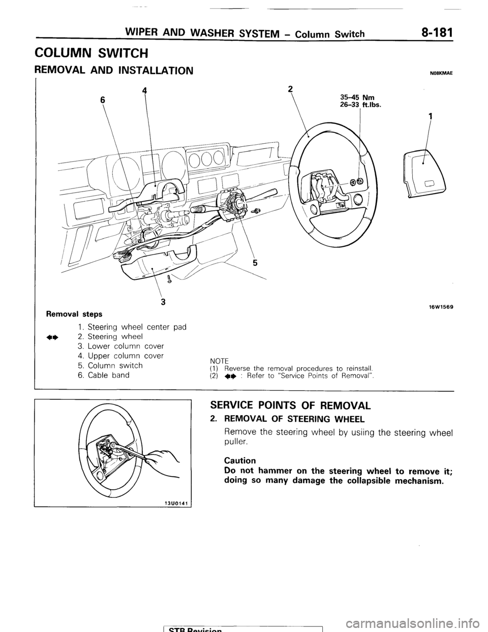
REMOVAL AND INSTALLATION NOBKMAE
35-45 Nm
Removal steps
3
l * 1. Steering wheel center pad
2. Steering wheel
3. Lower column cover
4. Upper column cover
5. Column switch
6. Cable band
NOTE
(1) Reverse the removal procedures to reinstall.
(2) *I) : Refer to “Service Points of Removal” 16W1569
SERVICE POINTS OF REMOVAL
2. REMOVAL OF STEERING WHEEL
Remove the steering wheel by usiing the steering wheel
puller.
Caution
Do not hammer on the steering wheel to remove it;
doing so many damage the collapsible mechanism.
) STB Revision
Page 203 of 284
WIPER AND WASHER SYSTEM - Rear Wiper and Washer Switch 8-183
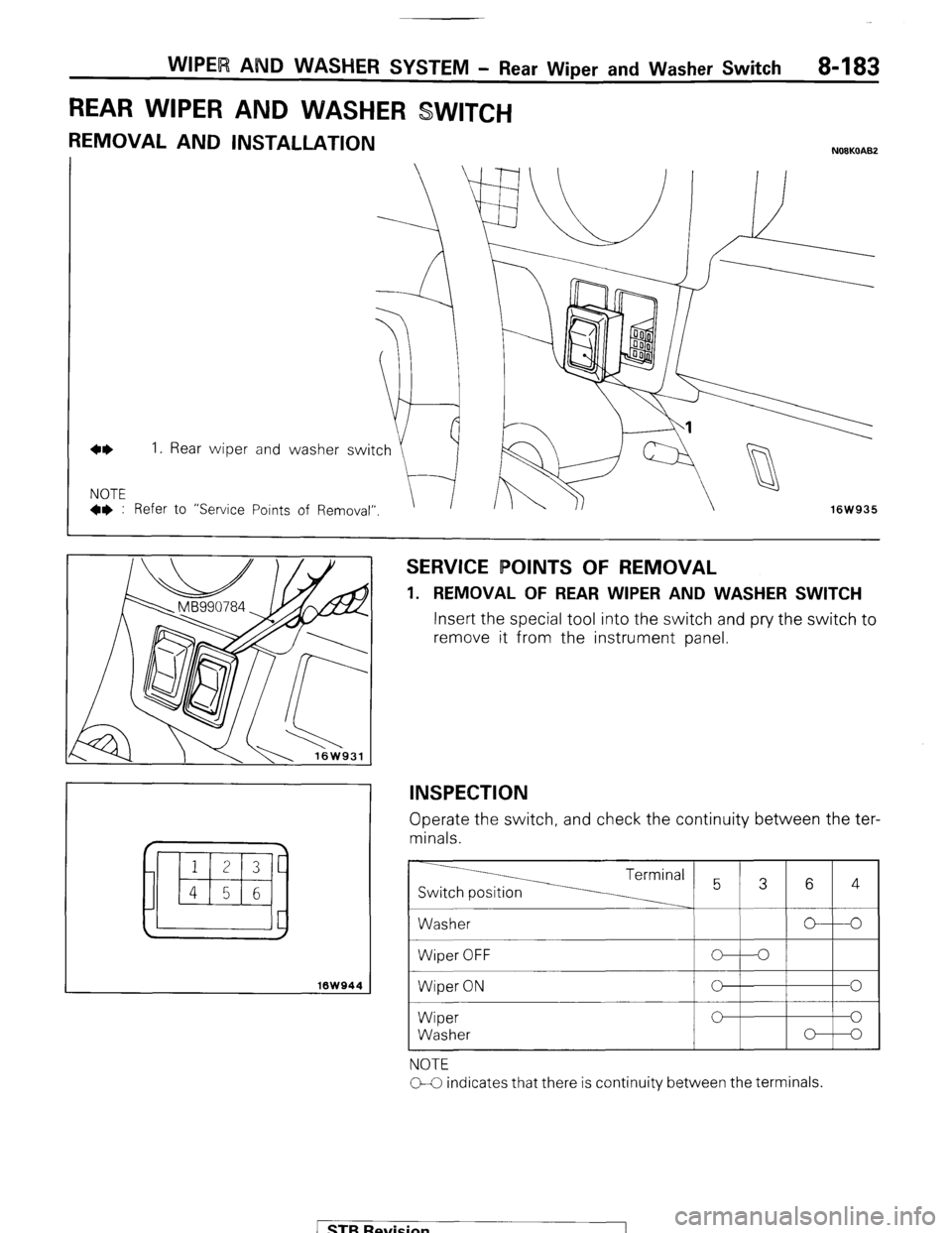
REAR WIPER AND WASHER SWITCH
REMOVAL AND INSTALLATION
4* I.
NOTE l * : Refer Rear wiper
to “Service
16W944
SERVICE POINTS OF REMOVAL
1. REMOVAL OF REAR WIPER AND WASHER SWITCH
Insert the special tool into the switch and pry the switch to
remove it from the instrument panel.
INSPECTION
Operate the switch, and check the continuity between the ter-
minals. ) STB Revision
Page 207 of 284
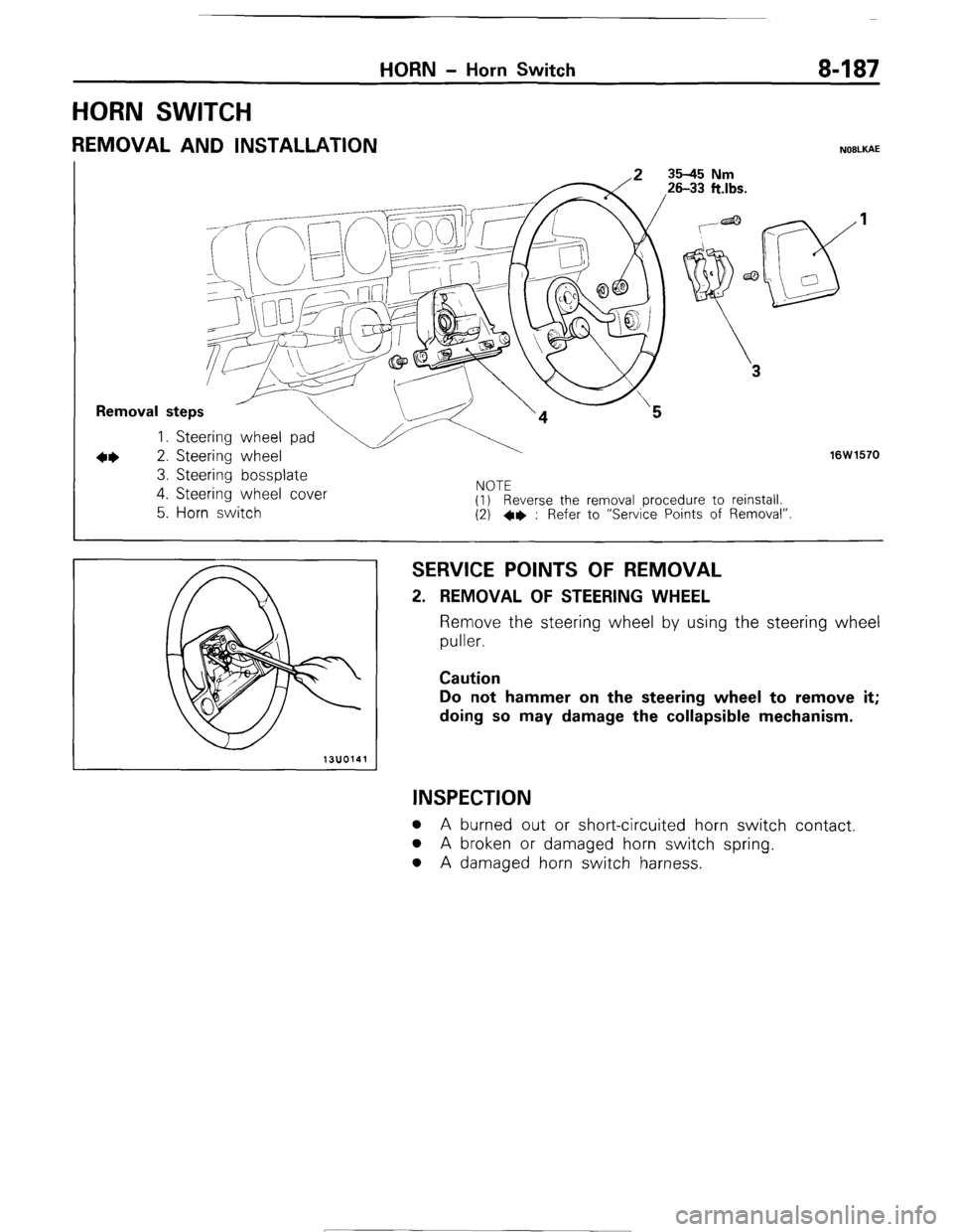
HORN SWITCH
HORN - Horn Switch 8-187
REMOVAL AND INSTALLATION NOILKAE
I T--J2
Removal steps
1. Steering wheel pa
+I) 2. Steering wheel
3. Steering bossplate
16W1570
4. Steering wheel cover
5. Horn switch I”” IL (1) Reverse the removal procedure to reinstall.
(2) +e : Refer to “Service Points of Removal”.
SERVICE POINTS OF REMOVAL 2. REMOVAL OF STEERING WHEEL
Remove the steering wheel by using the steering wheel
puller.
Caution
Do not hammer on the steering wheel to remove it;
doing so may damage the collapsible mechanism.
INSPECTION
l A burned out or short-circuited horn switch contact.
l A broken or damaged horn switch spring.
l A damaged horn switch harness. 1 STB Revision
Page 216 of 284
8-196 AUDIO SYSTEM - Service Adjustment Procedures
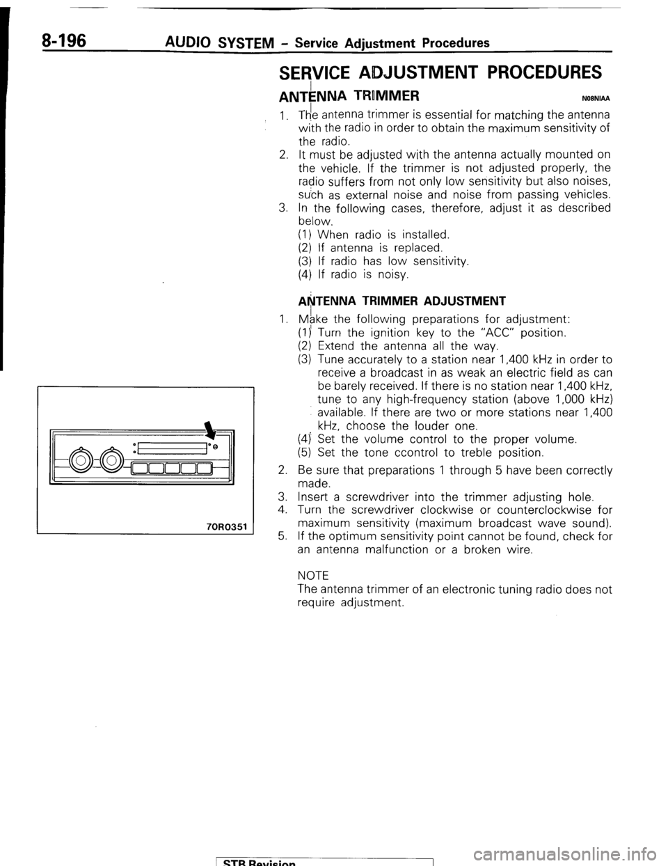
SERVICE ADJUSTMENT PROCEDURES
ANTkNNA TRUMMER NOBNIAA
70R0351
1.
2.
3.
1.
2.
3.
4.
5. The antenna trimmer is essential for matching the antenna
with the radio in order to obtain the maximum sensitivity of
the radio.
It must be adjusted with the antenna actually mounted on
the vehicle. If the trimmer is not adjusted properly, the
radio suffers from not only low sensitivity but also noises,
su’ch as external noise and noise from passing vehicles.
In the following cases, therefore, adjust it as described
below.
(1) When radio is installed.
(2) If antenna is replaced.
(3) If radio has low sensitivity.
(4) If radio is noisy.
AkTENNA TRIMMER ADJUSTMENT
Mgke the following preparations for adjustment:
(1)’ Turn the ignition key to the “ACC” position.
(2) Extend the antenna all the way.
(3) Tune accurately to a station near 1,400 kHz in order to
receive a broadcast in as weak an electric field as can
be barely received. If there is no station near 1,400 kHz,
tune to any high-frequency station (above 1,000 kHz)
available. If there are two or more stations near 1,400
kHz, choose the louder one.
(4) Set the volume control to the proper volume.
(5) Set the tone ccontrol to treble position.
Be sure that preparations 1 through 5 have been correctly
made.
Insert a screwdriver into the trimmer adjusting hole.
Tumrn the screwdriver clockwise or counterclockwise for
maximum sensitivity (maximum broadcast wave sound).
If the optimum sensitivity point cannot be found, check for
an antenna malfunction or a broken wire.
NOTE
The antenna trimmer of an electronic tuning radio does not
require adjustment.
/ STB Revision