Hazard switch MITSUBISHI MONTERO 1987 1.G Workshop Manual
[x] Cancel search | Manufacturer: MITSUBISHI, Model Year: 1987, Model line: MONTERO, Model: MITSUBISHI MONTERO 1987 1.GPages: 284, PDF Size: 14.74 MB
Page 21 of 284
8-1
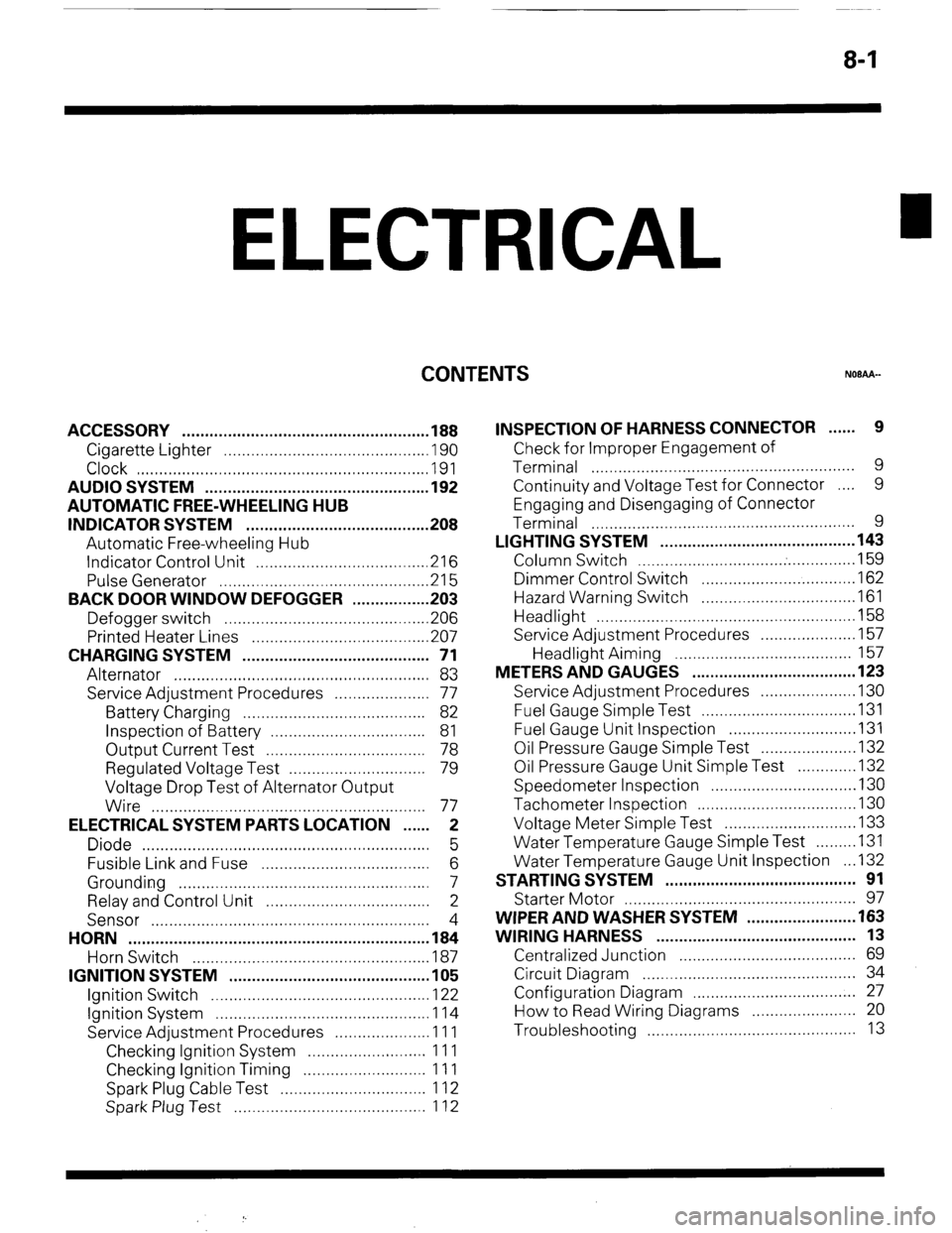
ELECTRICAL
CONTENTS
NOBAA-
ACCESSORY ......................................................
188
Cigarette Lighter ............................................
,190
Clock ...............................................................
,191
AUDIO SYSTEM ................................................
.192
AUTOMATIC FREE-WHEELING HUB
INDICATOR SYSTEM ........................................
208
Automatic Free-wheeling Hub
Indicator Control Unit
..................................... ,216
Pulse Generator ..............................................
215
BACK DOOR WINDOW DEFOGGER
................ .203
Defogger switch ............................................
,206
Printed Heater Lines
...................................... ,207
CHARGING SYSTEM .........................................
71
Alternator ........................................................
83
Service Adjustment Procedures
..................... 77
Battery Charging ........................................
82
Inspection of Battery ..................................
81
Output Current Test ...................................
78
Regulated Voltage Test ..............................
79
Voltage Drop Test of Alternator Output
Wire ............................................................
77
ELECTRICAL SYSTEM PARTS LOCATION
...... 2
Diode ...............................................................
5
Fusible Link and Fuse
..................................... 6
Grounding .......................................................
7
Relay and Control Unit ....................................
2
Sensor .............................................................
4
HORN ..................................................................
184
Horn Switch
.................................................... 187
IGNITION SYSTEM ............................................
105
Ignition Switch
................................................ 122
Ignition System ...............................................
1 14
Service Adjustment Procedures
.................... .l 1 1
Checking Ignition System
..........................
11 1
Checking Ignition Timing
...........................
11 1
Spark Plug Cable Test
................................
1 12
Spark Plug Test
.......................................... 1 12 INSPECTION OF HARNESS CONNECTOR ...... 9
Check for Improper Engagement of
Terminal .......................................................... 9
Continuity and Voltage Test for Connector .... 9
Engaging and Disengaging of Connector
Terminal ..........................................................
9
LIGHTING SYSTEM ........................................... 143
Column Switch
................................ .
.............. .I59
Dimmer Control Switch
................................. .I62
Hazard Warning Switch
................................. .I61
Headlight ........................................................ ,158
Service Adjustment Procedures
.................... .I57
Headlight Aiming .......................................
157
METERS AND GAUGES .................................... 123
Service Adjustment Procedures
.................... .I30
Fuel Gauge Simple Test ................................. .I31
Fuel Gauge Unit Inspection ........................... .I31
Oil Pressure Gauge Simple Test
.................... .I32
Oil Pressure Gauge Unit Simple Test
............ ,132
Speedometer Inspection
............................... .I30
Tachometer Inspection .................................. ,130
Voltage Meter Simple Test
............................ .I33
Water Temperature Gauge Simple Test
....... ..I3 1
Water Temperature Gauge Unit Inspection
. ..I3 2
STARTING SYSTEM .......................................... 91
Starter Motor ............ ....................................... 97
WIPER AND WASHER SYSTEM
....................... .163
WIRING HARNESS ............................................ 13
Centralized Junction ....................................... 69
Circuit Diagram ............................................... 34
Configuration Diagram .................................... 27
How to Read Wiring Diagrams ....................... 20
Troubleshooting .............................................. 13
Page 53 of 284
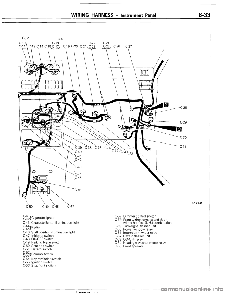
WIRING HARNESS - Instrument Panel 8-33
cy50 C149 Cl48 c-47
El$,}Cigarette lightet
C-43 Cigarette lighter illumination light
E::$ Radio
C-46 Shift position illumination light
C-47 Inhibitor switch
C-48 OD-OFF switch
C-49 Parking brake switch
C-50 Seat belt switch
C-51 Hazard switch
E3 Column switch
C-54 Key reminder switch
C-55 Ignition switch
C-56 Stop light switch C-57 Dimmer control switch
C-58 Front wiring harness and door
wiring harness (L.H.) combination
C-59 Turn-signal flasher unit
C-60 Power window relay
C-61 Intermittent wiper relay
C-62 Hazard flasher unit
C-63 OD-OFF relay
C-64 Headlight washer motor relay
C-65 Front speaker (L.H.)
Ision
Page 67 of 284
WIRING HARNESS - Dome Light Circuit 8-47
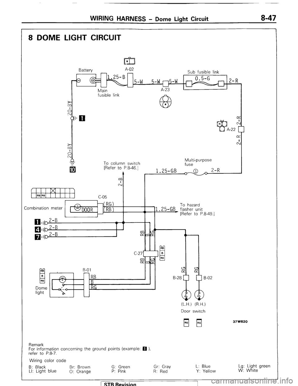
8 DOME LIGHT CIRCUIT
r
Battery A-02
Sub fusible link
3
1.25-B
2-w 0.5-G
5-w rl5-w m 2-R
u
A-23
Main
fusible link
To column switch
[Refer to P.8-46.1
m
A
t
Combination meter
C-27’
Dome
light B-01 Multi-purpose
fuse
1.25-GB
& 2-R
I-- To hazard
1.25-GB flasher unit
[Refer to P.8.49.1
(L.H.) (R.H.)
Door switch
37W620
Remark
For information concerning the ground points (example: 0 ),
refer to P.8-7.
Wiring color code
B: Black Br: Brown G: Green Gr: Gray L: Blue Lg: Light green
LI: Light blue
0: Orange P: Pink R: Red Y: Yellow W: White
1 STB Revision
Page 68 of 284
8-48 WIRING HARNESS - Turn-Signal and Hazard Light Circuit
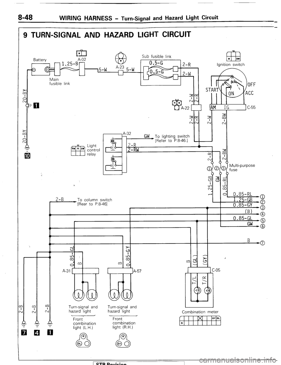
9 TURN-SIGNAL AND HAZARD LIGHT CIRCUIT
m 1 Sub fusible link
Battery A-02
- 1.25-B- a3 1 0.5-G
2-R
8 (5-W A-23 5-W
l-l
2-W El3 1 81 Ignition switch
r Main
fusible link
A-32
GW To lighting switch
e [Refer to P.8-46.1
2-R *
2-RW
I-
2-B To column switch
[Rear to P.8-461 I l.ZS-tit3 - a
t 'I 0.85-GY +
I_
(Bl -6
7 0.85-GL LO
I Gw -@ rn&
b-d 5
c-05
lzil
A-57
J CL
--.
I- I--
IG
Turn-signal and
hazard light Turn-signal and
hazard light
Combination meter
Front Front
combination
light (R.H.)
el
n 00
STB Revision
Page 69 of 284
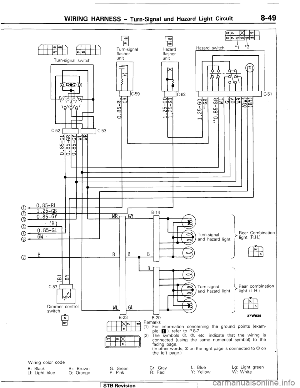
WIRING HARNESS - Turn-Signal and Hazard Light Circuit 8-49
OR
0 RI.
Turn-signal
flasher
GO
0 0.3
Hazard
flasher iazard switch “1 *2
1
Turn-signal switch unit unit
I
I
r
E
L:
ci
C
C-62
Rear Combination
light (R.H.) Turn-signal
and hazard light
-> mm
&
c-57 Rear combination
light (L.H.) light
OL
Em B Dimmer control
switch
m WL
-2 37W825
EJ
m “em~:~s~ ) refer to P.8-7. (1) For information concerning the ground points (exam-
(2) The symbols 0, 0, etc. indicate that the wiring is
connected (using the same numerical symbol) to the
facing page.
(In other words, 0 on the right page is connected to 0 on
the left page.)
Wiring color code
B: Black Br: Brown G: Green Gr: Gray L: Blue Lg: Light green
LI: Light blue
0: Orange P: Pink
R: Red Y: Yellow W: White
I
STB Revision
Page 70 of 284
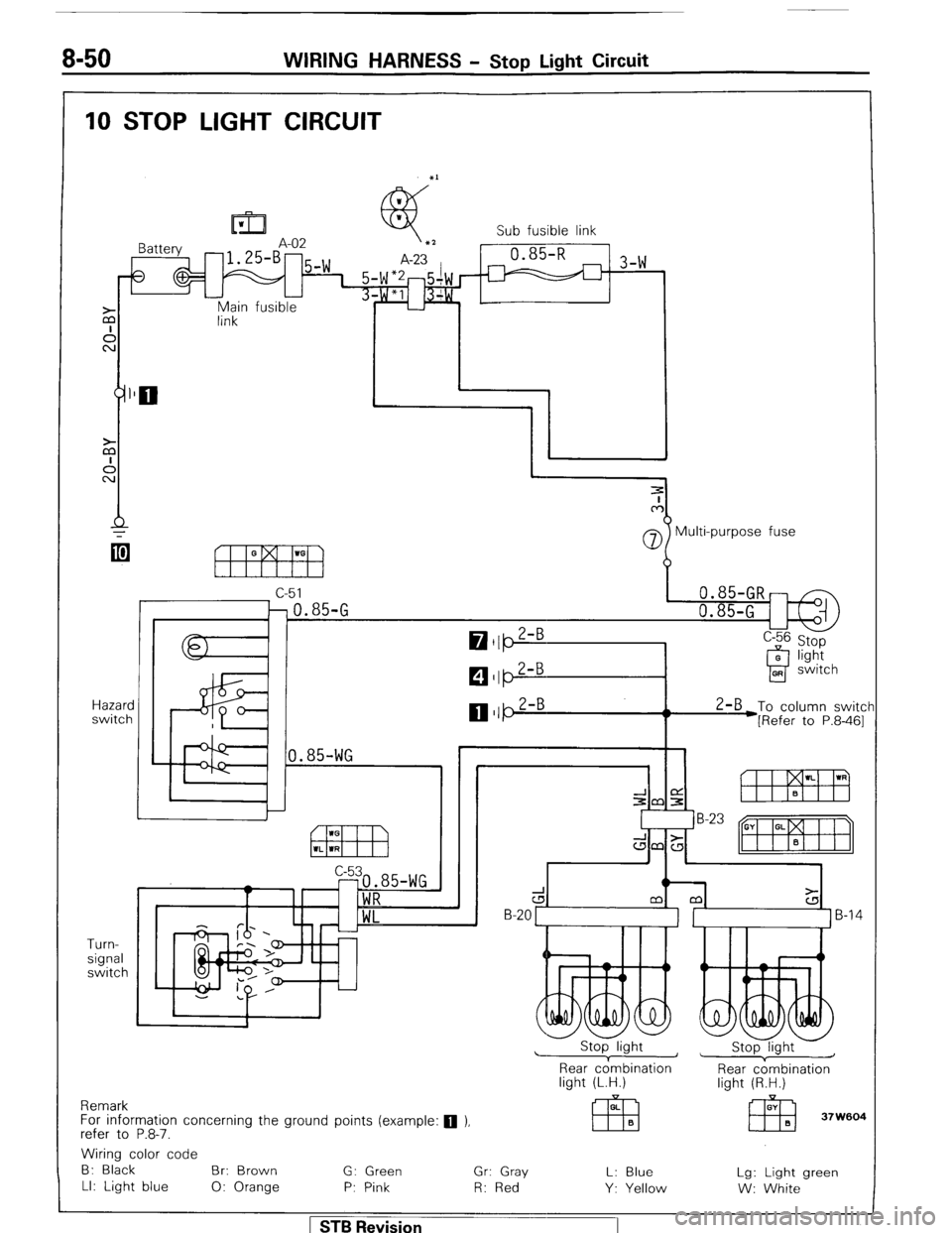
8-50 WIRING HARNESS - Stop Light Circuit
IO STOP LIGHT CIRCUIT
In3 1 Sub fusible link
A-07
Main fusible
link
Hazard
switch
Turn-
signal
switch Multi-purpose fuse
c-51
0.85-GR
0.85-G 0.85-G
1.85-WG 1 1 1 ,I
,I
$R
WL ’ (
Rear cdmbination
light (L.H.) Rear c:mbination
light (R.H.)
Remark
For information concerning the ground points (example: 0 ),
refer to P.8-7.
Wiring color code
B: Black Br: Brown
G: Green Gr: Gray L: Blue Lg: Light green
LI: Light blue
0: Orange P: Pink R: Red Y: Yellow W: White
1 STB Revision
Page 82 of 284
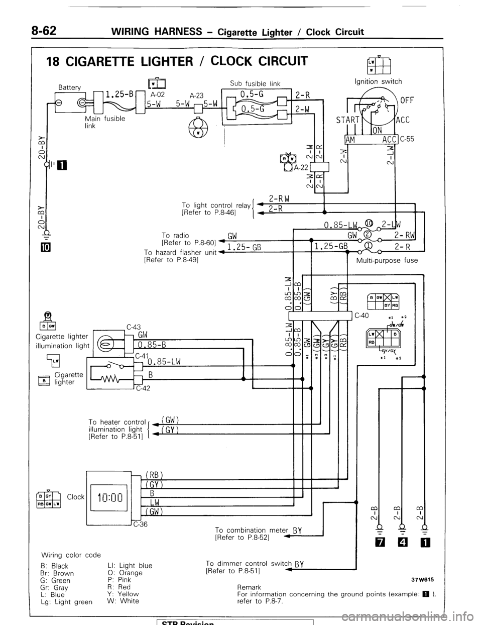
8-62 WIRING HARNESS - Cigarette Lighter / Clock Circuit
18 CIGARETTE LIGHTER / CLOCK CIRCUIT
Sub fusible link Ignition switch
r-l E-f? ‘) n
-u yn;in fusible
7-R \*I
To light control relay
[Refer to P.8-461
To radio
GW [Refer to P&601-, 3F- Pm
To hazard flasher unit4 I .LJ- G
[Refer to P.8-491
II I Multi-purpose fuse
illumination light
To heater control
illumination light
[Refer to P.8-511
Clock
CT
0: 1
h J
6
Jc-36
To combination mete& BY
[Refer to P.8-521 1
Wiring color code
B: Black LI: Light blue To dimmer control switch BY
Br: Brown 0: Orange [Refer to P.8-511 M
G: Green P: Pink
-
Gr: Gray H: Red
L: Blue Y: Yellow
Lg: Light green W: White Remark
For information concerning the ground points (example: 0 1,
refer to P.8-‘7.
Page 90 of 284
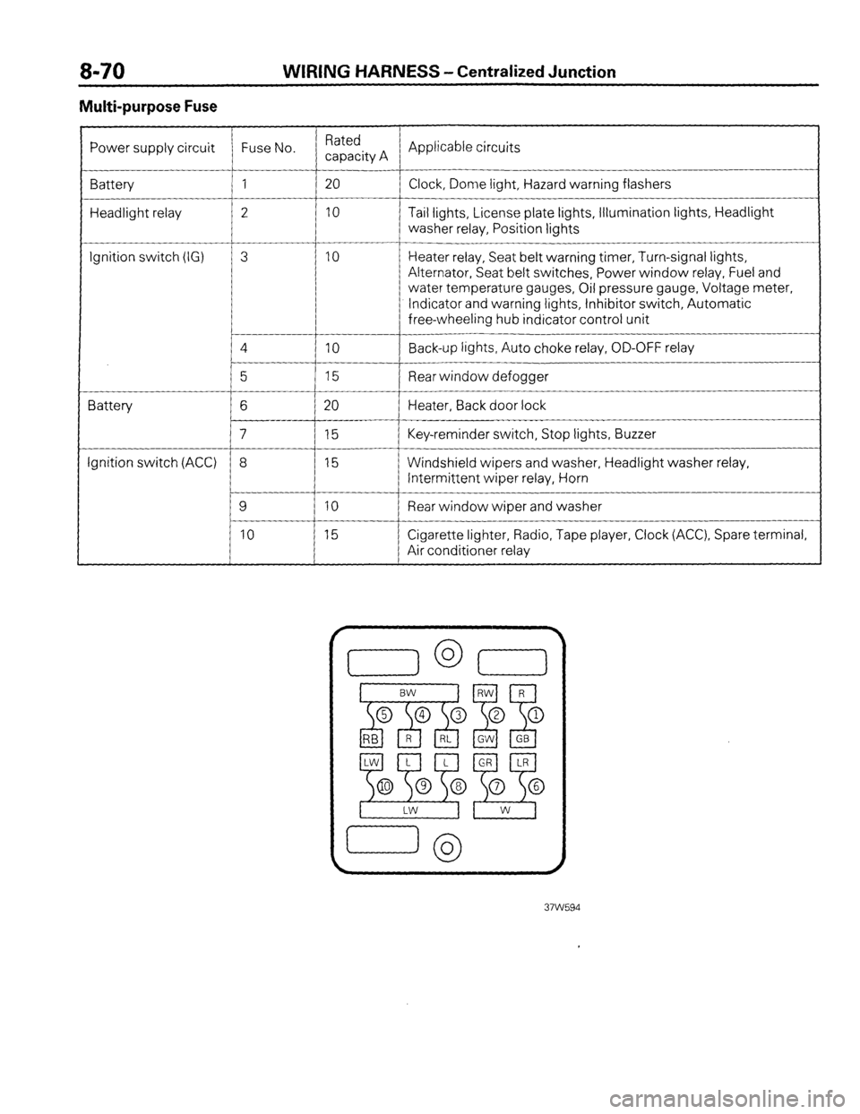
WIRING HARNESS - Centralized Junction
Multi-purpose Fuse
Power supply circuit Fuse No. Rated
capacity A Applicable circuits
Battery 1 20
Clock, Dome light, Hazard warning flashers
Headlight relay 2 10 Tail lights, License plate lights, Illumination lights, Headlight
washer relay, Position lights
__-
Ignition switch (IG) 3 10 Heater relay, Seat belt warning timer, Turn-signal lights,
Alternator, Seat belt switches, Power window relay, Fuel and
water temperature gauges, Oil pressure gauge, Voltage meter,
Indicator and warning lights, Inhibitor switch, Automatic
free-wheeling hub indicator control unit
4
IO Back-up lights, Auto choke relay, OD-OFF relay
__-
5 15 Rear window defogger
Battery 6 20 Heater, Back door lock
7 15 Key-reminder switch, Stop lights, Buzzer
Ignition switch (ACC) 8 15 Windshield wipers and washer, Headlight washer relay,
Intermittent wiper relay, Horn
9 10 Rear window wiper and washer
10 15 Cigarette lighter, Radio, Tape player, Clock (ACC), Spare terminal,
Air conditioner relay
Page 161 of 284
METERS AND GAUGES - Indicators and Warning Lights 8-141
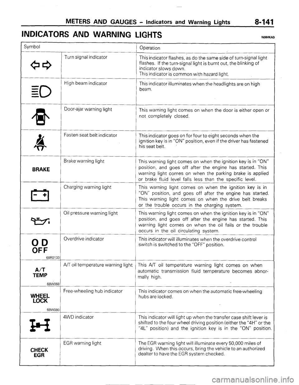
INDICATORS AND WARNING
LIGHTS
Symbol
Operation
Turn signal indicator
+e3 This indicator flashes, as do the same side of turn-signal light
flashes. If the turn-signal light is burnt out, the blinking of
indicator slows down.
This indicator is common with hazard light.
0
High beam indicator
- This indicator illuminates when the headlights are on high
= beam.
=
* Door-ajar warning light
This warning light comes on when the door is either open or
not completely closed.
4 Fasten seat belt indicator
This indicator goes on for four to eight seconds when the
ignition key is in “ON” position, even if the driver has fastened
his seat belt.
BRAKE
Brake warning light
This warning light comes on when the ignition key is in “ON”
position, and goes off after the engine has started. This
warning light comes on when the parking brake is applied
or brake fluid level falls less than the specific level.
III Charging warning light This warning light comes on when the ignition key is in
- + “ON” position, and goes off after the engine has started.
This warning light comes on when the drive belt breaks
or the trouble occurs in the charging system.
Oil pressure warning light This warning light comes on when the ignition key is in “ON”
P position, and goes off after the engine has started. This
warning light comes on when the oil fails or the trouble
occurs in the oil circulating system.
00
Overdrive indicator
This indicator will illuminates when the overdrive control
OFF
switch is switched to the “OFF” position.
68R0133
A/T
A/T oil temperature warning light This A/T oil temperature warning light comes on when
TEMP automatic transmission fluid temperature becomes abnor-
mally high.
68WO68
Free-wheeling hub indicator
YEL This indicator comes on when the automatic free-wheeling
hubs are locked.
68WO80
z4 4WD indicator This indicator will light up when the transfer case shift lever is
shifted to the four wheel driving position (either the “4H” or the
“4L” position) and the ignition key is in the “ON” position.
CHECK
EGR
EGR warning light The EGR warning light will illuminate every 50,000 miles of
driving. When this occurs, bring the vehicle to an authorized
dealter to have the EGR system checked.
) STB Revision
Page 164 of 284
8-144
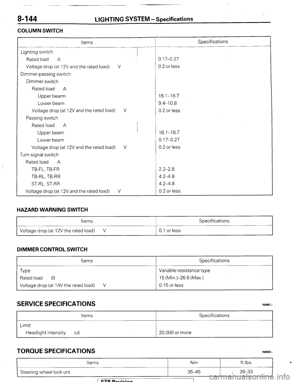
COLUMN SWITCH LIGHTING
SYSTEM -Specifications
Items Specifications
Lighting switch
Rated load A 0.17-0.27
Voltage drop (at 12V and the rated load) V 0.2 or less
Dimmer-passing switch
Dimmer switch
Rated load A
Upper bearm 16.1-18.7
Lower beam 9.4-10.8
Voltage drop (at 12V and the rated load) V 0.2 or less
Passing switch
Rated load A I
Upper beam I
16.1-18.7
Lower beam 0.17-0.27
Voltage drop (at 12V and the rated load)
V 0.2 or less
Turn signal switch
Rated load A
TB-FL, TB-FR 2.2-2.8
TB-RL, TB-R R 4.2-4.8
ST-RL, ST-RR 4.2-4.8
Voltage drop (at 12V and the rated load)
V 0.2 or less
HAZARD WARNING SWITCH
Items Specifications
I Voltage drop (at 12V the rated load) V 0.1 or less
I
DIMMER CONTROL SWITCH
Items Specifications
Type Variable-resistance type
Rated load n 15 (Min.)-26.6 (Max.)
Voltage drop (at 14V the rated load) V 0.15 or less
SERVICE SPECIFICATIONS
Items Specifications
Limit
Headlight intensity cd 20,000 or more
TORQUE SPECIFICATIONS
I
Items Nm ft.lbs.
N08lb
Steering wheel lock unt 35-45 I. 26-33
I
1 STB Revision