Hazard switch MITSUBISHI MONTERO 1987 1.G User Guide
[x] Cancel search | Manufacturer: MITSUBISHI, Model Year: 1987, Model line: MONTERO, Model: MITSUBISHI MONTERO 1987 1.GPages: 284, PDF Size: 14.74 MB
Page 165 of 284
LIGHTING SYSTEM - Special tools / Troubleshooting
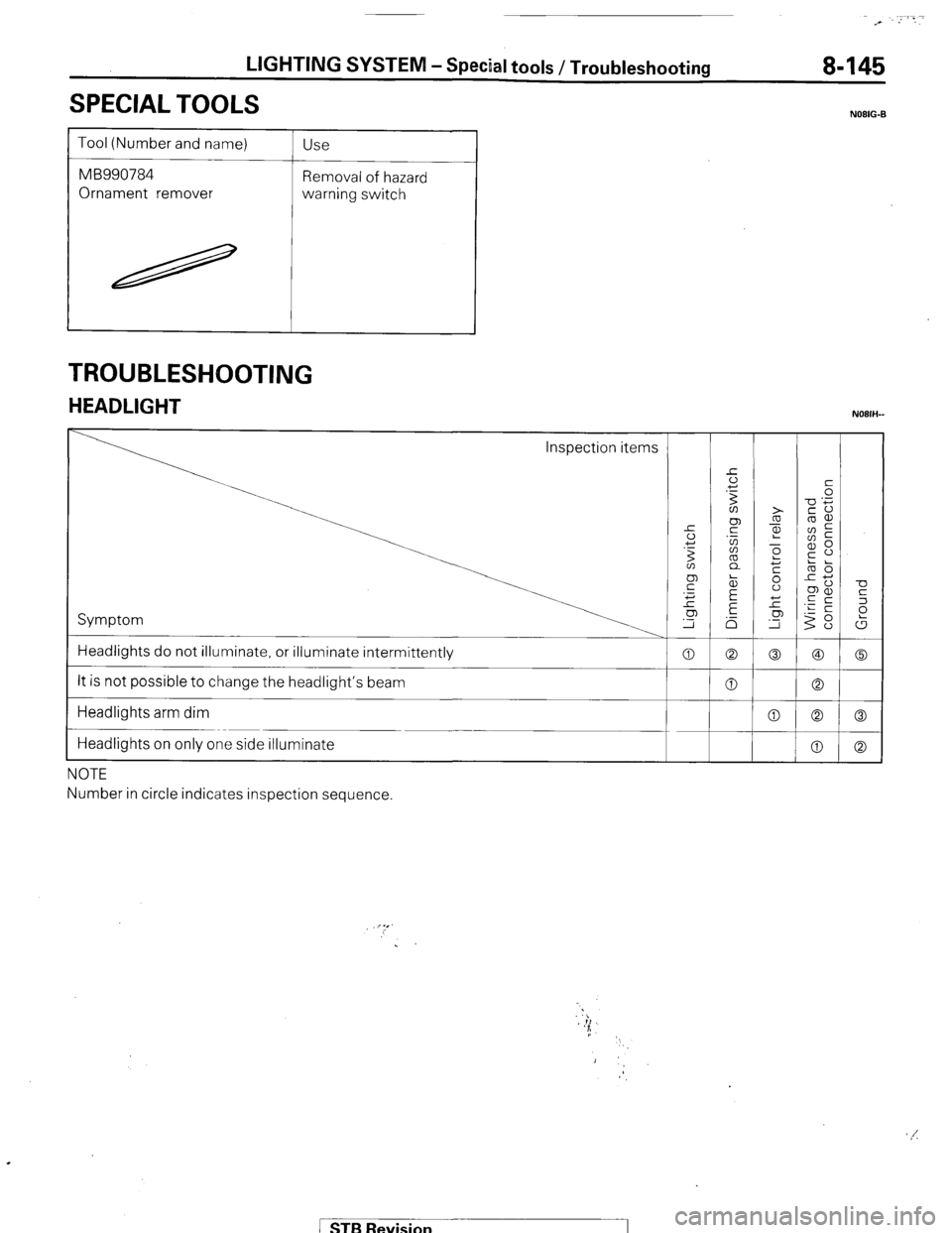
SPECIAL TOOLS
Tool (Number and name)
MB990784
Ornament remover Use
Removal of hazard
warning switch
TROUBLESHOOTING
HEADLIGHT
Inspection items
1 Symptom
Headlights do not illuminate, or illuminate intermittently
It is not possible to change the headlight’s beam
Headlights arm dim
Headlights on only one side illuminate
NOTE
Number in circle indicates inspection sequence. 0
0
0
NOIIG-B
-0
K
2
t
0
0
0 ( STB Revision
Page 167 of 284
LIGHTING SYSTEM - Troubleshooting 8-147
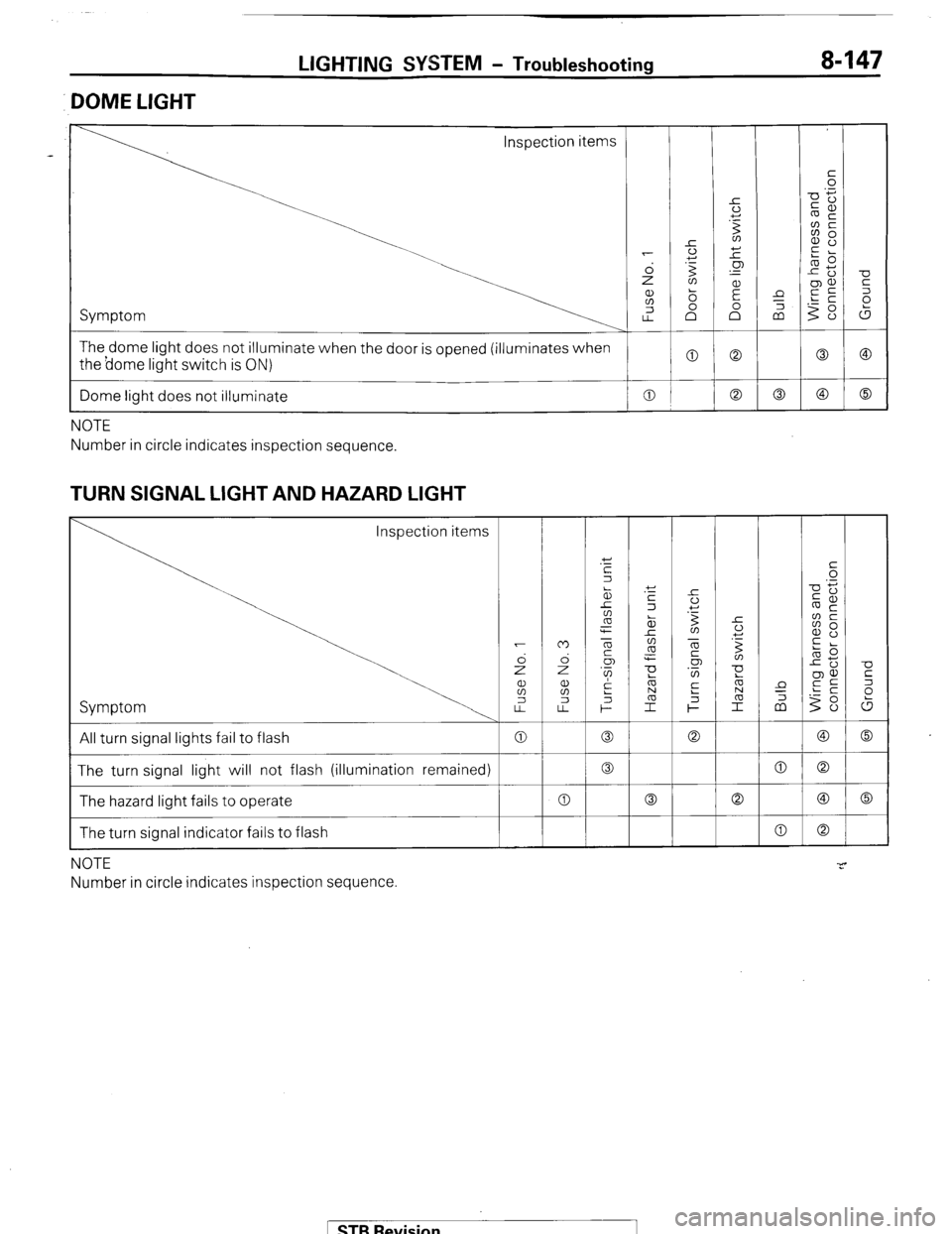
DOME LIGHT
Inspection items
The dome light does not illuminate when the door is opened (illuminates when
the borne light switch is ON)
I
Dome light does not illuminate 0
I
NOTE
Number in circle indicates inspection sequence.
TURN SIGNAL LIGHT AND HAZARD LIGHT
Inspection items
Symptom
All turn signal lights fail to flash
The turn signal light will not flash (illumination remained)
The hazard light fails to operate
The turn signal indicator fails to flash
NOTE
Number in circle indicates inspection sequence
1 STB Revision
Page 172 of 284
8-152 LIGHTING SYSTEM - Circuit Diagram
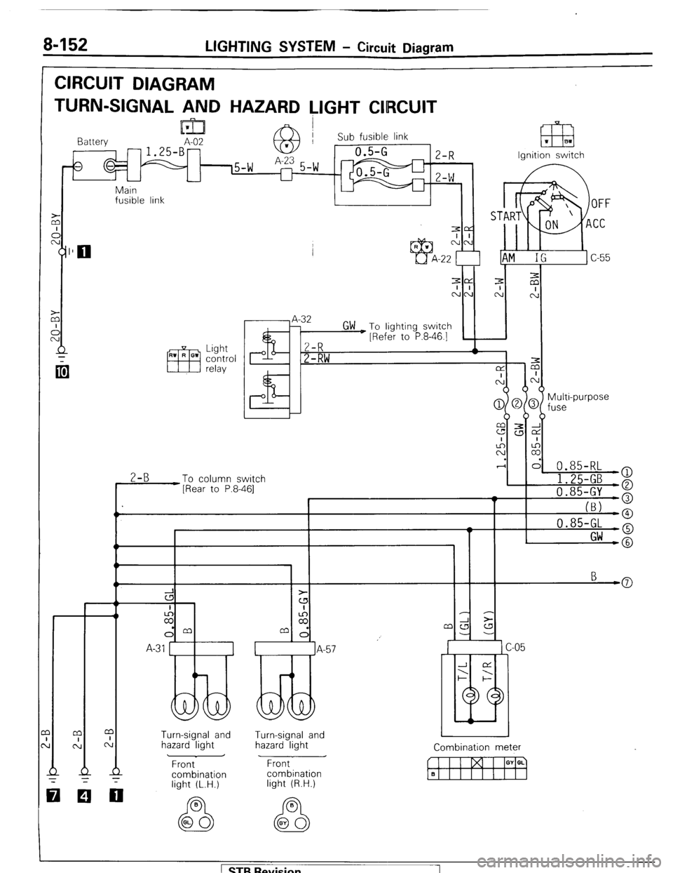
CIRCUIT DIAGRAM
TURN-SIGNAL AND HAZARD LIGHT CIIRCUIT
lml I Battery A-02 -1.25-B- 63 Sub fusible link 1 m 1 BI
Ignition switch
Main
fusible link
I 1
.I
-
z
I I I ’ I
Multi-purpose
fuse
0.85-RL
2-B
To column switch
[Rear to P.8-461 I 1.25-GB )
a
I 'I 0.85-GY o
I_
(BJ -0 0.85-GL -o
I Gw -@
3
cs
I
z
dm
A-31 1
Turn-signal and
hazard light Turn-signal and
hazard light
Front
combination Combination meter
w I I I GY a. q Front
combination
light (R.H.)
000
light (L.H.)
1 STB Revision 1
Page 173 of 284
LIGHTING SYSTEM - Circuit Diagram 8-153
Turn-signal
flasher Hazard
flasher I iazard switch “1
unit unit
I r Turn-srgnal switch
I
l!d C-62
a
I
::
C
-W‘\*1W++ n
c
I
::
C
n
*
‘\&VB/
I v-l--c 0.85-RL
o- 1 ')r r-
Rear Combination
light (R.H.) Turn -signal
and hazard light B
Y-
a- B B
Dimmer control
switch Rear combination
light (L.H.) OL
EZB B
WL
37W029 B-20
-
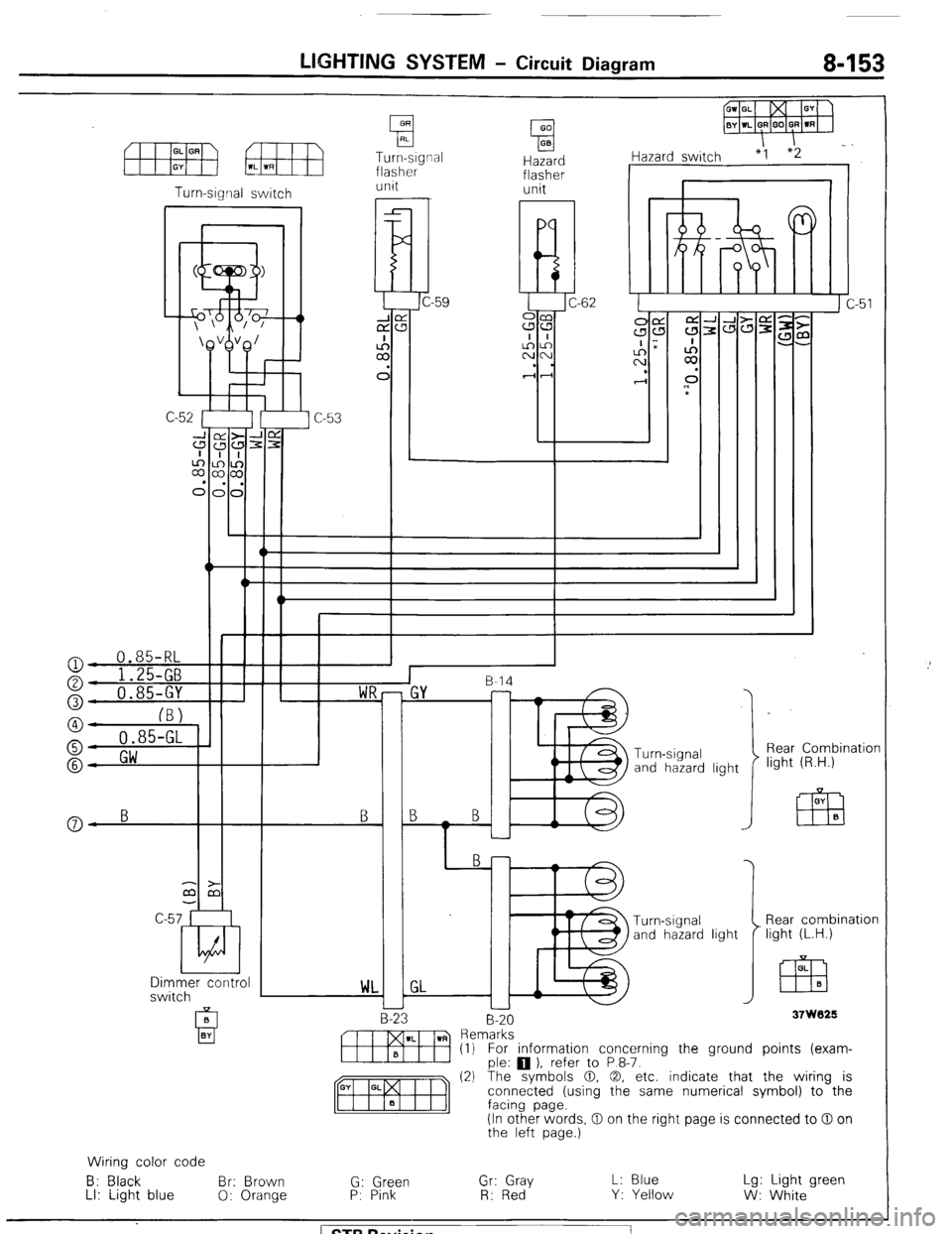
m Rern~:~s~ ) refer to P 8-7. (1) For information concerning the ground points (exam-
(2) The symbols 0. 0, etc. indicate that the wiring is
connected (using the same numerical symbol) to the
(In other words, 0 on the right page is connected to 0 on
the left page.)
Wiring color code
B: Black Br: Brown
G: Green Gr: Gray L: Blue Lg: Light green
LI: Light blue
0: Orange P: Pink
R: Red Y: Yellow
W: White ) STB Revision
Page 174 of 284
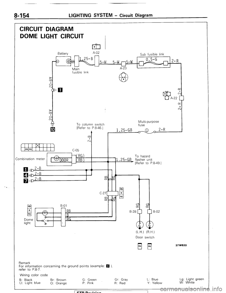
8-154 LIGHTING SYSTEM - Circuit Diagram
CIRCUIT DIAGRAM
DOME LIGHT CIRCUIT
I=32 v
Battery A-02
Sub fusible link
1
0.5-G
5-w 5-w r-l5-w 1 2-R
u
Main I A-23 I
I
fusible IInk
63 *
L
To column switch
Combination meter To hazard
EL B-01 RB
El B
RF
RB H-28
B
RG
(L.H.) (R.H.)
Door switch
Remark
For information concerning the ground points (example: 0 ),
refer to P.8-7. 37W020
Wiring color code
B: Black Br: Brown G: Green Gr: Gray L: Blue Lg: Light green
LI: Light blue
0: Orange P: Pink
R: Red Y: Yellow W: White
1 STB Revision
Page 175 of 284
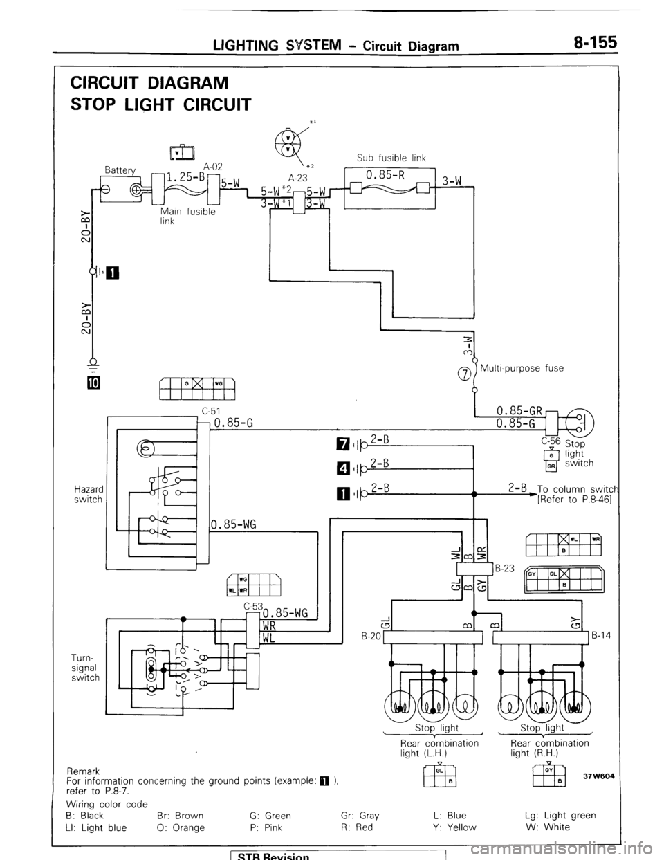
LIGHTING SYSTEM - Circuit Diagram 8-155
CIRCUIT DIAGRAM
STOP LIGHT CIRCUIT
Main fusible
link
Hazard
switch
Turn-
signal
switch Sub fusible link
-1 3-w
07 Multr-purpose fuse
c-51
-0.85-G
0.85-WG 2-B
To column switcf
*[Refer to P.8-461
Remark
For information concerning the ground points (example:
q ).
refer to P.8-7.
d B-20 1 ]B-14
Stop light ~
1 Stop light
Rear cdmbination
light (L.H.) Rear c;mbination
light (R.H.)
Wiring color code
B: Black Br: Brown G: Green Gr: Gray L: Blue Lg: Light green
Ll: Light blue 0: Orange P: Pink R: Red Y. Yellow W: White
1 STB Revision
Page 181 of 284
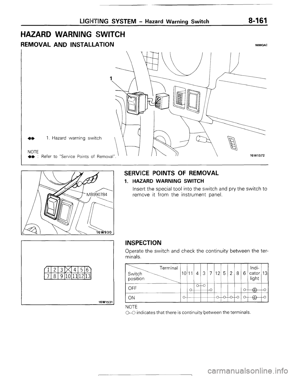
LIGHTING SYSTEM - Hazard Warning Switch 8-161
HAZARD WARNING
REMOVAL AND INSTALLATION NOBICLAC
16W1531
SERVOCE POINTS OF REMOVAL
1. HAZARD WARNING SWITCH
Insert the special tool into the switch and pry the switch to
remove it from the instrument panel.
INSPECTION
Operate the switch and check the continuity between the ter-
minals.
NOTE
CC indicates that there is continuity between the terminals.
STB Revision
Page 209 of 284
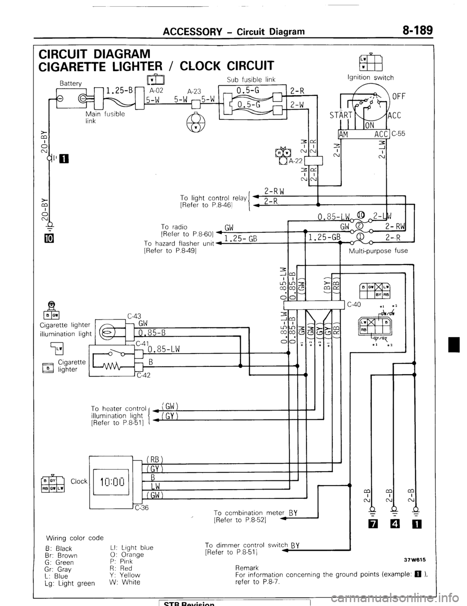
ACCESSORY - Circuit Diagram 8-189
CIRCUIT DIAGRAM
LW
CIGARETTE LIGHTER / CLOCK CIRCUIT EB w
Sub fusible link
,-fs q M 15-W 5-W 25-W m ;I;
I I
-
Main fusible -
link Ignition switch
3e
I I
NN
,
Z-RW To
linht cnntrnl r&v I 4 0 n
I 1 - .J . __._ - -., [Refer to P.8-461
I 4 L-K A
To radio
GW [Refer to P.8-601 + 1 .25- GB
To hazard flasher unit4
[Refer to P.8-491
Multi-purpose fuse
illumination light
’ To heater control
illumination light
[Refer to P 8-511
r
i I
To combination meter BY
Wiring color code
B: Black LI: Light blue
Br: Brown 0: Orange
G: Green P: Pink
Gr: Gray R: Red
L: Blue Y: Yellow
Lg: Light green W: White
I
I - - m
I
N
Q
-
[Refer to P.8-521 -
To dimmer control switch BY
[Refer to P 8-511 .I
Remark 37W615
For information concerning the ground points (example: 0 ).
refer to P.8-7.
1 STB Revision