Ignition MITSUBISHI MONTERO 1987 1.G Workshop Manual
[x] Cancel search | Manufacturer: MITSUBISHI, Model Year: 1987, Model line: MONTERO, Model: MITSUBISHI MONTERO 1987 1.GPages: 284, PDF Size: 14.74 MB
Page 1 of 284
Service Manual
MONTERO
1987 : Volume 2
FOREWORD
This Service Manual has been prepared with the
latest service information available at the time of
publication. It is subdivided into various group
categories and each section contains diagnosis,
disassembly, repair, and installation procedures
along with complete specifications and tightening
references. Use of this manual will aid in properly
performing any servicing necessary to maintain or
restore the high levels of performance and reliability
designed into these outstanding vehicles.
WE SUPPORT
VOLUNTARY TECHNICIAN
CERTIFICATION THROUGH
MITSUBISHI MOTOR SALES OF AMERICA. Inc.
Mitsubishi Motors corporation reserves the right to make changes in
design or to make additions to or improvements in its products without
imposing any obligations upon itself to install them on its products
previously manufactured.
I
GROUP/SECTION INDEX ‘kme-.
INTRODUCTION ..............................
Electrical ...........................................
Electrical System Parts
Location .........................................
Relays, Control Units, Sensors,
Fuses, Groundings
Inspection of Harness
Connector ......................................
Wiring Harness .............................
Charging System ..........................
Starting System ............................
Ignition System .............................
Meters and Gauges ......................
Lighting System .............................
Wiper and Washer System ..........
Horn ...............................................
Accessory ......................................
Audio System ................................
Back Door Window Defogger ......
Automatic Free-wheeling Hub
Indicator System ..........................
Heaters and Air-conditioning .........
Heaters ..........................................
Air-conditioning ............................
**, For Engine Chassis & Body refer to
0 1986 Mitsubishi Motors Corporation Printed in Japan
Page 9 of 284
INTRODUCTION - Precautions Before Service 9
nm (in.)
so0059
PARTS
When replacing parts, use MITSUBISHI genuine parts.
VEHICLE WVASHING
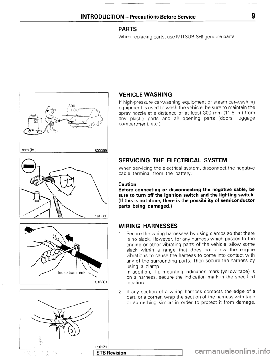
If high-pressure car-washing equipment or steam car-washing
equipment is used to wash the vehicle, be sure to maintain the
spray nozzle at a distance of at least 300 mm (1 1.8 in.) from
any plastic parts and all opening parts (doors, luggage
compartment, etc.).
SERVICING THE ELECTRICAL SYSTEM
When servicing the electrical system, disconnect the negative
cable terminal from the battery.
Caution
Before connecting or disconnecting the negative cable, be
sure to turn off the ignition switch and the lighting switch.
(If this is not done, there is the possibility of semiconductor
parts being damaged.)
WIRING HARNESSES
1. Secure the wiring harnesses by using clamps so that there
is no slack. However, for any harness which passes to the
engine or other vibrating parts of the vehicle, allow some
slack within a range that does not allow the engine
vibrations to cause the harness to come into contact with
any of the surrounding parts. Then secure the harness by
using a clamp.
In addition, if a mounting indication mark (yellow tape) is
on a harness, secure the indication mark in the specified
location.
2. If any section of a wiring harness contacts the edge of a
part, or a corner, wrap the section of the harness with tape
or something similar in order to protect it from damage.
F161711
* :, :, 1 STB Revision
Page 21 of 284
8-1
ELECTRICAL
CONTENTS
NOBAA-
ACCESSORY ......................................................
188
Cigarette Lighter ............................................
,190
Clock ...............................................................
,191
AUDIO SYSTEM ................................................
.192
AUTOMATIC FREE-WHEELING HUB
INDICATOR SYSTEM ........................................
208
Automatic Free-wheeling Hub
Indicator Control Unit
..................................... ,216
Pulse Generator ..............................................
215
BACK DOOR WINDOW DEFOGGER
................ .203
Defogger switch ............................................
,206
Printed Heater Lines
...................................... ,207
CHARGING SYSTEM .........................................
71
Alternator ........................................................
83
Service Adjustment Procedures
..................... 77
Battery Charging ........................................
82
Inspection of Battery ..................................
81
Output Current Test ...................................
78
Regulated Voltage Test ..............................
79
Voltage Drop Test of Alternator Output
Wire ............................................................
77
ELECTRICAL SYSTEM PARTS LOCATION
...... 2
Diode ...............................................................
5
Fusible Link and Fuse
..................................... 6
Grounding .......................................................
7
Relay and Control Unit ....................................
2
Sensor .............................................................
4
HORN ..................................................................
184
Horn Switch
.................................................... 187
IGNITION SYSTEM ............................................
105
Ignition Switch
................................................ 122
Ignition System ...............................................
1 14
Service Adjustment Procedures
.................... .l 1 1
Checking Ignition System
..........................
11 1
Checking Ignition Timing
...........................
11 1
Spark Plug Cable Test
................................
1 12
Spark Plug Test
.......................................... 1 12 INSPECTION OF HARNESS CONNECTOR ...... 9
Check for Improper Engagement of
Terminal .......................................................... 9
Continuity and Voltage Test for Connector .... 9
Engaging and Disengaging of Connector
Terminal ..........................................................
9
LIGHTING SYSTEM ........................................... 143
Column Switch
................................ .
.............. .I59
Dimmer Control Switch
................................. .I62
Hazard Warning Switch
................................. .I61
Headlight ........................................................ ,158
Service Adjustment Procedures
.................... .I57
Headlight Aiming .......................................
157
METERS AND GAUGES .................................... 123
Service Adjustment Procedures
.................... .I30
Fuel Gauge Simple Test ................................. .I31
Fuel Gauge Unit Inspection ........................... .I31
Oil Pressure Gauge Simple Test
.................... .I32
Oil Pressure Gauge Unit Simple Test
............ ,132
Speedometer Inspection
............................... .I30
Tachometer Inspection .................................. ,130
Voltage Meter Simple Test
............................ .I33
Water Temperature Gauge Simple Test
....... ..I3 1
Water Temperature Gauge Unit Inspection
. ..I3 2
STARTING SYSTEM .......................................... 91
Starter Motor ............ ....................................... 97
WIPER AND WASHER SYSTEM
....................... .163
WIRING HARNESS ............................................ 13
Centralized Junction ....................................... 69
Circuit Diagram ............................................... 34
Configuration Diagram .................................... 27
How to Read Wiring Diagrams ....................... 20
Troubleshooting .............................................. 13
Page 37 of 284
Normal close INC) type
Deenergized state
Energized state
I
WIRING HARNESS - Troubleshooting 8-17
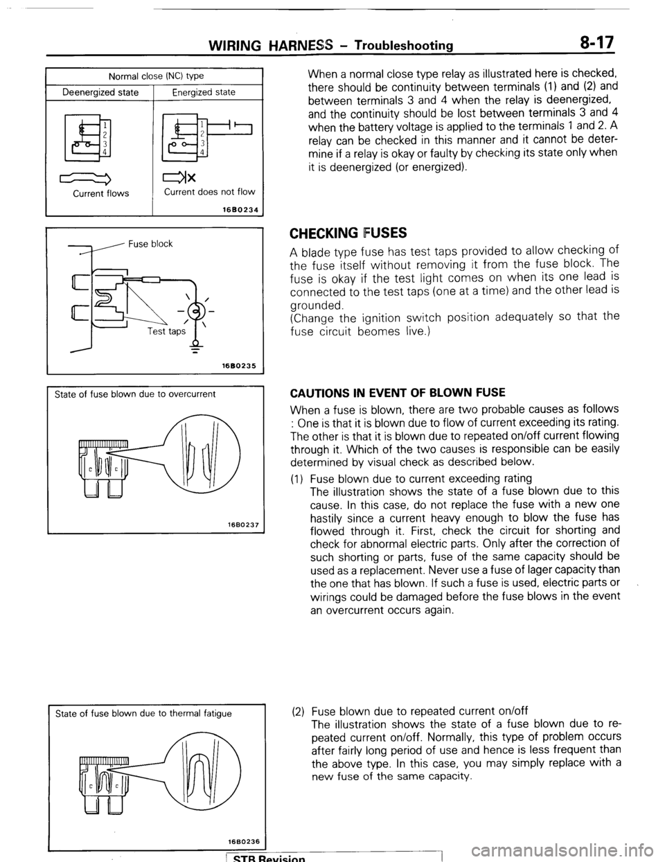
When a normal close type relay as illustrated here is checked,
there should be continuity between terminals (1) and (2) and
between terminals 3 and 4 when the relay is deenergized,
and the continuity should be lost between terminals 3 and 4
when the battery voltage is applied to the terminals 1 and 2. A
relay can be checked in this manner and it cannot be deter-
mine if a relay is okay or faulty by checking its state only when
it is deenergized (or energized).
Current -flows Current does not flow
1680234
=
1680235
State of fuse blown due to overcurrent
1660237
I
State of fuse blown due to thermal fatigue
CHECKING FUSES
A blade type fuse has test taps provided to allow checking of
the fuse itself without removing it from the fuse block. The
fuse is okay if the test light comes on when its one lead is
connected to the test taps (one at a time) and the other lead is
grounded.
(Change the ignition switch position adequately so that the
fuse circuit beomes live.)
CAUTIONS IN EVENT OF BLOWN FUSE
When a fuse is blown, there are two probable causes as follows
: One is that it is blown due to flow of current exceeding its rating.
The other is that it is blown due to repeated on/off current flowing
through it. Which of the two causes is responsible can be easily
determined by visual check as described below.
(1) Fuse blown due to current exceeding rating
The illustration shows the state of a fuse blown due to this
cause. In this case, do not replace the fuse with a new one
hastily since a current heavy enough to blow the fuse has
flowed through it. First, check the circuit for shorting and
check for abnormal electric parts. Only after the correction of
such shorting or parts, fuse of the same capacity should be
used as a replacement. Never use a fuse of lager capacity than
the one that has blown. If such a fuse is used, electric parts or
wirings could be damaged before the fuse blows in the event
an overcurrent occurs again.
(2) Fuse blown due to repeated current on/off
The illustration shows the state of a fuse blown due to re-
peated current on/off. Normally, this type of problem occurs
after fairly long period of use and hence is less frequent than
the above type. In this case, you may simply replace with a
new fuse of the same capacity.
Page 42 of 284
8-22 WIRING HARNESS - How to Read Wiring Diagrams
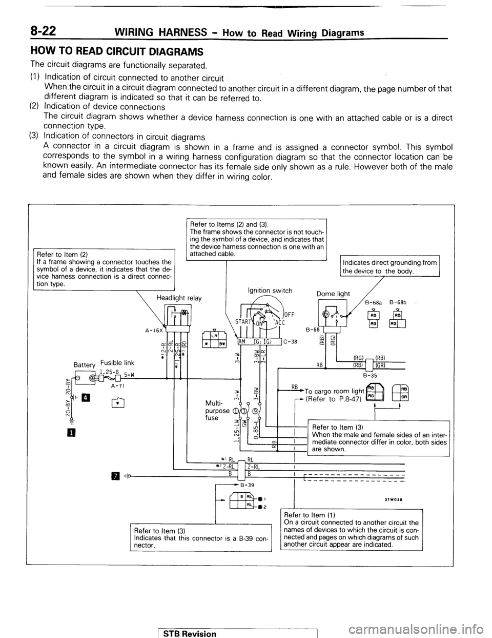
HOW TO READ CIRCUIT DIAGRAMS
The circuit diagrams are functionally separated.
(1) Indication of circuit connected to another circuit
When the circuit in a circuit diagram connected to another circuit in a different diagram, the page number of that
different diagram is indicated so that it can be referred to.
(2) Indication of device connections
The circuit diagram shows whether a device harness connection is one with an attached cable or is a direct
connection type.
(3) Indication of connectors in circuit diagrams
A connector in a circuit diagram is shown in a frame and is assigned a connector symbol. This symbol
corresponds to the symbol in a wiring harness configuration diagram so that the connector location can be
known easily. An intermediate connector has its female side only shown as a rule. However both of the male
and female sides are shown when they differ in wiring color.
Refer to Item (2)
If a frame showing a connector touches the
?. it indicates that the de-
a direct connec- symbol of a device
vice
harness connectlon IS
tion type.
Refer to Items (2) and (3).
The frame shows the connector is not touch- ing the symbol of a device, and indicates that
the device harness connection is one with an
attached cable.
Indicates direct grounding from
the device to the bodv.
Ignition switch
Dome light
/
17 /B-6& B-68b
(RG) - (RB)
RB-
(REV 1 I (GR)
L-2
B-35
1 *I RL - RL
I
**2-RL 1 Z-RL I
BI B ----- ---- --------
L ----_ __---___----
r------B-39
43 BRL *I
31103LI RL*2 _
Refer to Item (1)
Refer to item (3)
Indicates that this connector is a B-39 con-
nectar. On a circuit connected to another circuit the
names of devices to which the circuit is con-
nected and pages on which diagrams of such
another circuit appear are indicated.
1 STB Revision 1
Page 43 of 284
WIRING HARNESS - HOW BO Read Wiring Diagrams 8-23
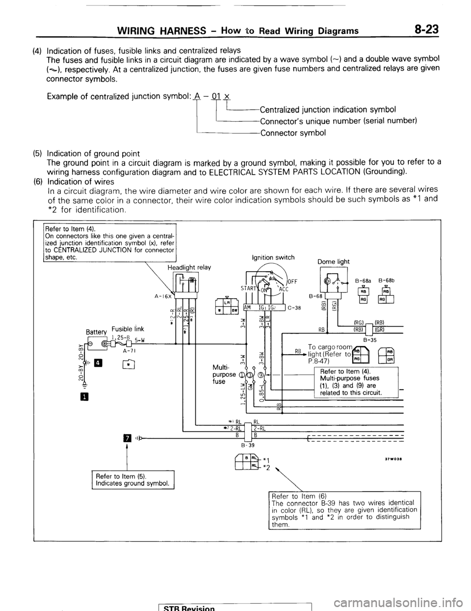
(4) Indication of fuses, fusible links and centralized relays
The fuses and fusible links in a circuit diagram are indicated by a wave symbol (-) and a double wave symbol
(~1, respectively. At a centralized junction, the fuses are given fuse numbers and centralized relays are given
connector symbols.
Example of centralized junction symbol: A - 01 x
Centralized junction indication symbol
Connector’s unique number (serial number)
Connector symbol
(5) Indication of ground point
The ground point in a circuit diagram is marked by a ground symbol, making it possible for you to refer to a
wiring harness configuration diagram and to ELECTRICAL SYSTEM PARTS LOCATION (Grounding).
(6) Indication of wires
In a circuit diagram, the wire diameter and wire color are shown for each wire. If there are several wires
of the same color in a connector, their wire color indication symbols should be such symbols as “I and
“2 for identification.
On connectors like this one given a central-
to CENTRALIZED JUNCTION for connector
1 shaoe. etc.
-I Headlight relay ignition switch
Dome light
I II I B-35 B-68b
P:8-47)
IEU
I ’ 2 I
RL
2-RL
0 III- BI B -----____________
L - - - - - _ _ _ _ _ __ _ _ _ _ _
B-39
Refer to Item (5).
Refer to Item (6)
The connector B-39 has two wires identical
in color (RL), so they are given identification
symbols *I and *2 in order to distinguish
them. 1 ST6 Revision
Page 44 of 284
8-24 WIRING HARNESS - How to Read Wiring Diagrams
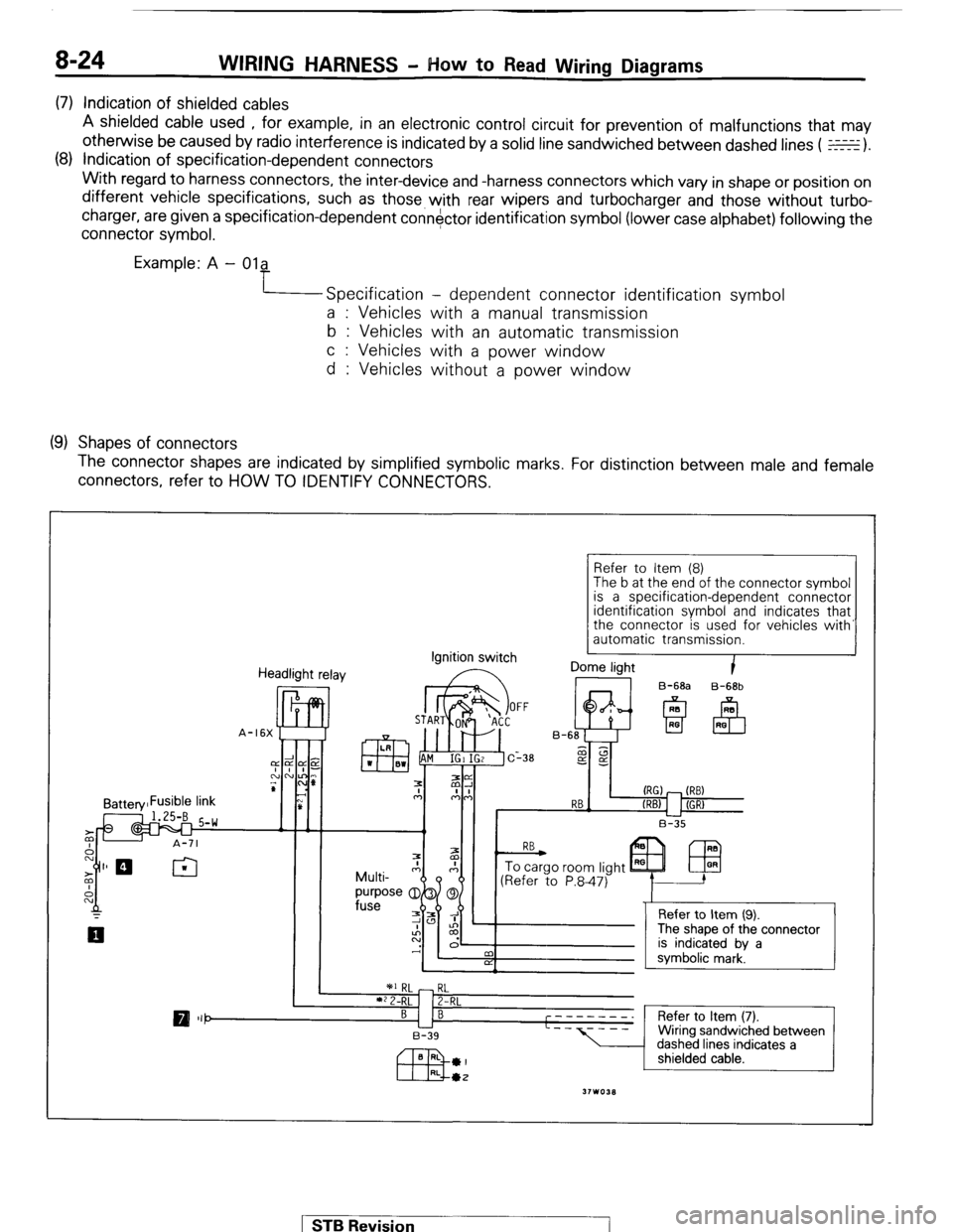
(7) Indication of shielded cables
A shielded cable used , for example, in an electronic control circuit for prevention of malfunctions that may
otherwise be caused by radio interference is indicated by a solid line sandwiched between dashed lines ( E).
(8) Indication of specification-dependent connectors
With regard to harness connectors, the inter-device and -harness connectors which vary in shape or position on
different vehicle specifications, such as those with rear wipers and turbocharger and those without turbo-
charger, are given a specification-dependent connector identification symbol (lower case alphabet) following the
connector symbol.
Example: A - Ola
Specification - dependent connector identification symbol
a : Vehicles with a manual transmission
b : Vehicles with an automatic transmission
c : Vehicles with a power window
d : Vehicles without a power window
(9) Shapes of connectors
The connector shapes are indicated by simplified symbolic marks. For distinction between male and female
connectors, refer to HOW TO IDENTIFY CONNECTORS.
Refer to Item (8)
The b at the end of the connector symbol
is a specification-dependent connector
identification
symbol and indicates that
the connector is used for vehicles with’
automatic transmission.
Headlight relay Ignition
switch I Dome light
B-68a B-68b STB Revision
Page 49 of 284
WIRING- HARNESS - Engine Compartment 8-29
; A-06 A-08 A-1 0 A-12 A-14
,.
1 A-15 8
I I
,I I I, I /
A-48
WI
&-ii& ’
A-35 Ai34 A!33 J-3:
A-39 A-37
36W618
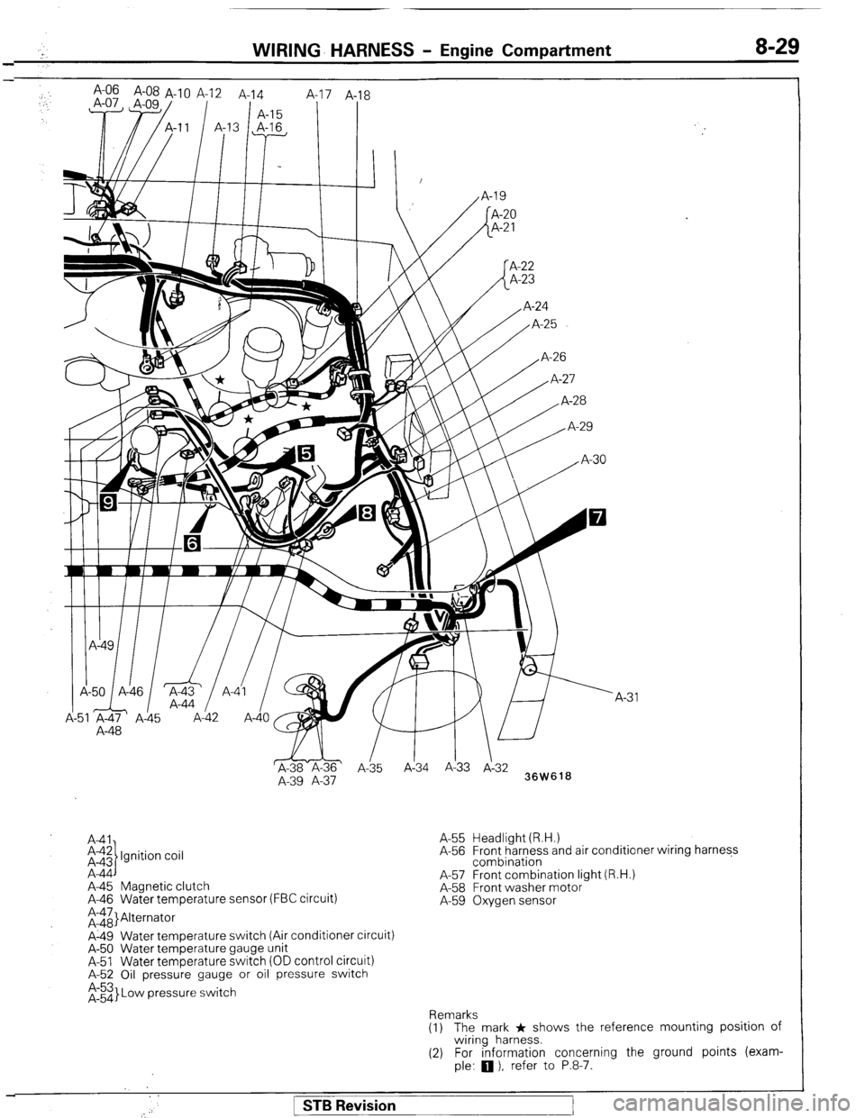
A41
i-$ Ignition coil
A-44
A-45 Magnetic clutch
A-46 Water temperature sensor (FBC circuit)
;rii}Alternator
A-49 Water temperature switch (Air conditioner circuit)
A-50 Water temperature gauge unit
A-51 Water temperature switch (OD control circuit)
A-52 Oil pressure gauge or oil pressure switch
$3 Low pressure switch A-55 Headlight (R.H.)
A-56 Front harness and air conditioner wiring harness
combination
A-57 Front combination light (R.H.)
A-58 Front washer motor
A-59 Oxygen sensor
Remarks
(1) The mark * shows the reference mounting position of
wiring harness.
(2) For information concerning the ground points (exam-
ple:
q ), refer to P.8-7.
1 STB Revision
Page 53 of 284
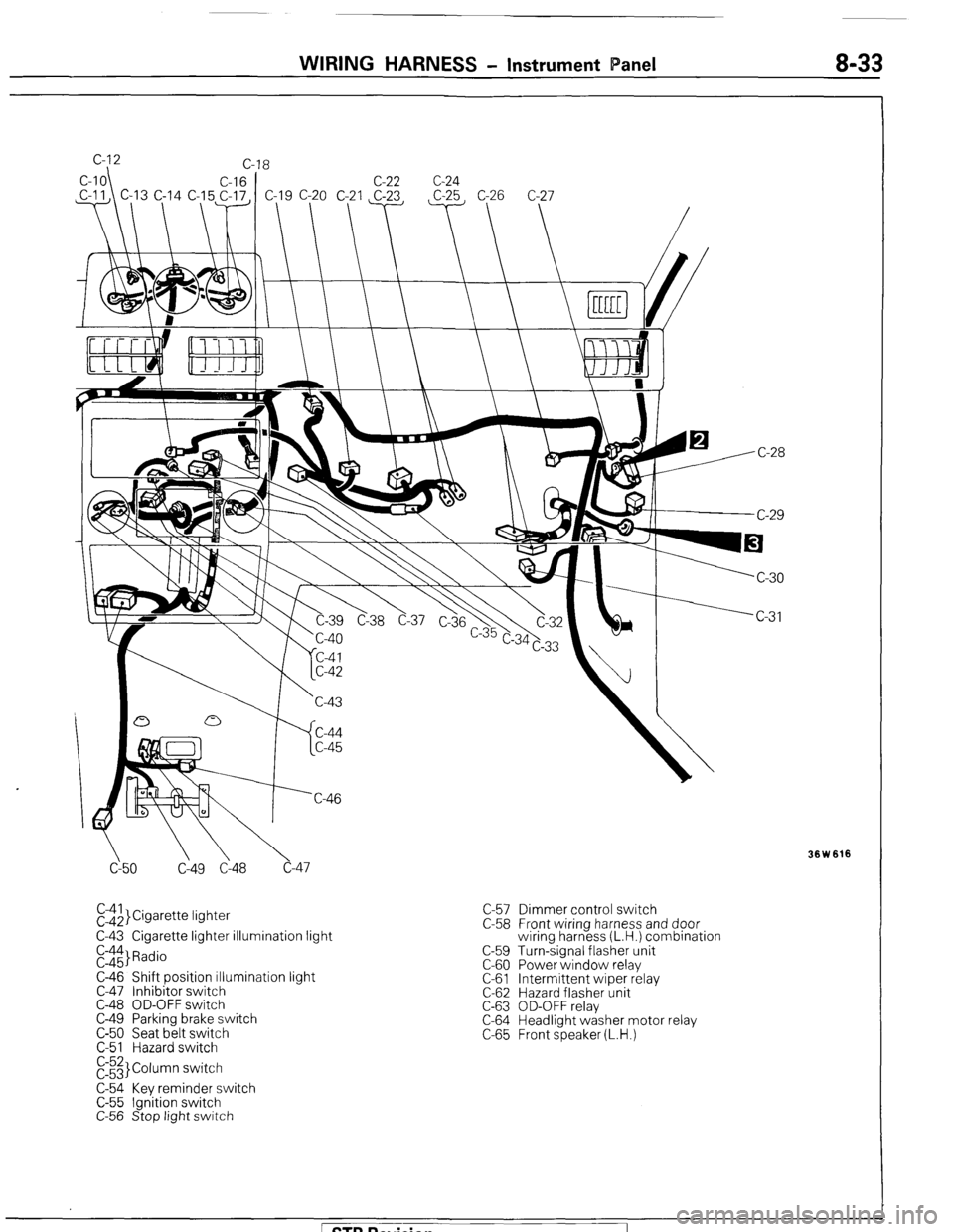
WIRING HARNESS - Instrument Panel 8-33
cy50 C149 Cl48 c-47
El$,}Cigarette lightet
C-43 Cigarette lighter illumination light
E::$ Radio
C-46 Shift position illumination light
C-47 Inhibitor switch
C-48 OD-OFF switch
C-49 Parking brake switch
C-50 Seat belt switch
C-51 Hazard switch
E3 Column switch
C-54 Key reminder switch
C-55 Ignition switch
C-56 Stop light switch C-57 Dimmer control switch
C-58 Front wiring harness and door
wiring harness (L.H.) combination
C-59 Turn-signal flasher unit
C-60 Power window relay
C-61 Intermittent wiper relay
C-62 Hazard flasher unit
C-63 OD-OFF relay
C-64 Headlight washer motor relay
C-65 Front speaker (L.H.)
Ision
Page 54 of 284
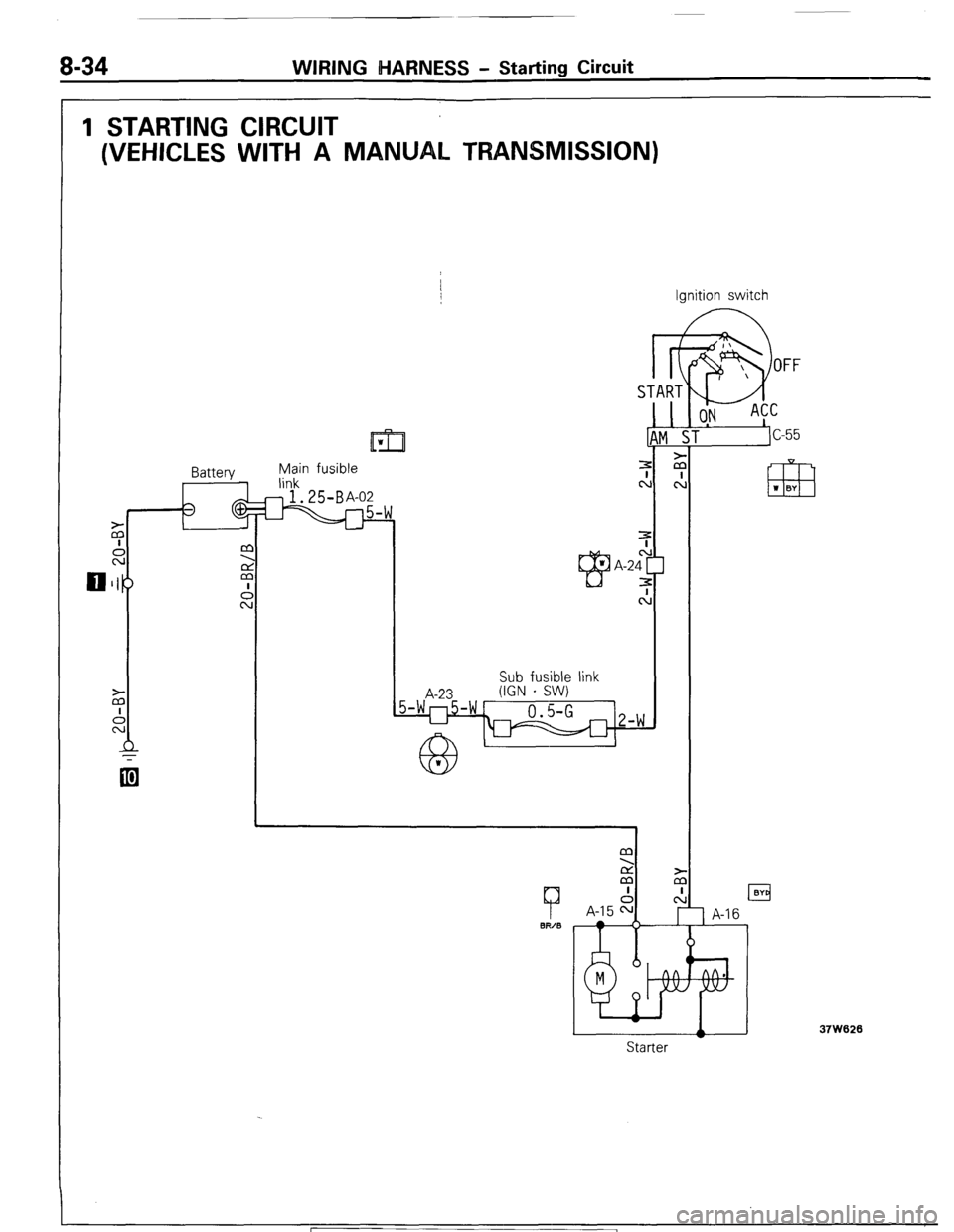
8-34 WIRING MARNESS - Starting Circuit
1 STARTING CIRCUIT
(VEHICLES WITH A MANUAL TRANSMISSION)
Ignition switch
Battery Main fusible
link
@.25B+
A-23 Sub fusible link
(IGN - SW)
7
BIT/B
M
2
M
I
A-15 F=
TA RT
L
1!
z
cl
m w BY
A
Starter
37W620
1 STB Revision