service indicator MITSUBISHI MONTERO 1987 1.G Workshop Manual
[x] Cancel search | Manufacturer: MITSUBISHI, Model Year: 1987, Model line: MONTERO, Model: MITSUBISHI MONTERO 1987 1.GPages: 284, PDF Size: 14.74 MB
Page 1 of 284
Service Manual
MONTERO
1987 : Volume 2
FOREWORD
This Service Manual has been prepared with the
latest service information available at the time of
publication. It is subdivided into various group
categories and each section contains diagnosis,
disassembly, repair, and installation procedures
along with complete specifications and tightening
references. Use of this manual will aid in properly
performing any servicing necessary to maintain or
restore the high levels of performance and reliability
designed into these outstanding vehicles.
WE SUPPORT
VOLUNTARY TECHNICIAN
CERTIFICATION THROUGH
MITSUBISHI MOTOR SALES OF AMERICA. Inc.
Mitsubishi Motors corporation reserves the right to make changes in
design or to make additions to or improvements in its products without
imposing any obligations upon itself to install them on its products
previously manufactured.
I
GROUP/SECTION INDEX ‘kme-.
INTRODUCTION ..............................
Electrical ...........................................
Electrical System Parts
Location .........................................
Relays, Control Units, Sensors,
Fuses, Groundings
Inspection of Harness
Connector ......................................
Wiring Harness .............................
Charging System ..........................
Starting System ............................
Ignition System .............................
Meters and Gauges ......................
Lighting System .............................
Wiper and Washer System ..........
Horn ...............................................
Accessory ......................................
Audio System ................................
Back Door Window Defogger ......
Automatic Free-wheeling Hub
Indicator System ..........................
Heaters and Air-conditioning .........
Heaters ..........................................
Air-conditioning ............................
**, For Engine Chassis & Body refer to
0 1986 Mitsubishi Motors Corporation Printed in Japan
Page 21 of 284
8-1
ELECTRICAL
CONTENTS
NOBAA-
ACCESSORY ......................................................
188
Cigarette Lighter ............................................
,190
Clock ...............................................................
,191
AUDIO SYSTEM ................................................
.192
AUTOMATIC FREE-WHEELING HUB
INDICATOR SYSTEM ........................................
208
Automatic Free-wheeling Hub
Indicator Control Unit
..................................... ,216
Pulse Generator ..............................................
215
BACK DOOR WINDOW DEFOGGER
................ .203
Defogger switch ............................................
,206
Printed Heater Lines
...................................... ,207
CHARGING SYSTEM .........................................
71
Alternator ........................................................
83
Service Adjustment Procedures
..................... 77
Battery Charging ........................................
82
Inspection of Battery ..................................
81
Output Current Test ...................................
78
Regulated Voltage Test ..............................
79
Voltage Drop Test of Alternator Output
Wire ............................................................
77
ELECTRICAL SYSTEM PARTS LOCATION
...... 2
Diode ...............................................................
5
Fusible Link and Fuse
..................................... 6
Grounding .......................................................
7
Relay and Control Unit ....................................
2
Sensor .............................................................
4
HORN ..................................................................
184
Horn Switch
.................................................... 187
IGNITION SYSTEM ............................................
105
Ignition Switch
................................................ 122
Ignition System ...............................................
1 14
Service Adjustment Procedures
.................... .l 1 1
Checking Ignition System
..........................
11 1
Checking Ignition Timing
...........................
11 1
Spark Plug Cable Test
................................
1 12
Spark Plug Test
.......................................... 1 12 INSPECTION OF HARNESS CONNECTOR ...... 9
Check for Improper Engagement of
Terminal .......................................................... 9
Continuity and Voltage Test for Connector .... 9
Engaging and Disengaging of Connector
Terminal ..........................................................
9
LIGHTING SYSTEM ........................................... 143
Column Switch
................................ .
.............. .I59
Dimmer Control Switch
................................. .I62
Hazard Warning Switch
................................. .I61
Headlight ........................................................ ,158
Service Adjustment Procedures
.................... .I57
Headlight Aiming .......................................
157
METERS AND GAUGES .................................... 123
Service Adjustment Procedures
.................... .I30
Fuel Gauge Simple Test ................................. .I31
Fuel Gauge Unit Inspection ........................... .I31
Oil Pressure Gauge Simple Test
.................... .I32
Oil Pressure Gauge Unit Simple Test
............ ,132
Speedometer Inspection
............................... .I30
Tachometer Inspection .................................. ,130
Voltage Meter Simple Test
............................ .I33
Water Temperature Gauge Simple Test
....... ..I3 1
Water Temperature Gauge Unit Inspection
. ..I3 2
STARTING SYSTEM .......................................... 91
Starter Motor ............ ....................................... 97
WIPER AND WASHER SYSTEM
....................... .163
WIRING HARNESS ............................................ 13
Centralized Junction ....................................... 69
Circuit Diagram ............................................... 34
Configuration Diagram .................................... 27
How to Read Wiring Diagrams ....................... 20
Troubleshooting .............................................. 13
Page 101 of 284
CHARGING SYSTEM - Service Adjustment Procedures 8-81
(2) Upon completion of the test, set the engine speed at idle and
turn off the ignition switch.
(3) Disconnect the battery ground cable.
(4) Remove the test voltmeter and ammeter and the engine ta-
chometer.
(5) Connect the alternator output wire to the alternator “B” ter-
minal.
(6) Connect the battery ground cable.
ll3Y1848 2. Remove battery from vehicle.
Caution
White
I Blue
I Care should be taken in the event battery case is cracked
or leaking to protect hands from the electrolyte. A suit-
able pair of rubber gloves (not the household type) should
be worn when removing battery by hand.
3. Inspect battery carrier for damage caused by loss of acid from
battery. If acid damage is present, it will be necessary to clean
area with a solution of clean warm water and baking soda.
Scrub area with a stiff bristle brush and wipe off with a cloth
moistened with ammonia or baking soda in water.
4. Clean top of battery with same solutions as described in Step
(3).
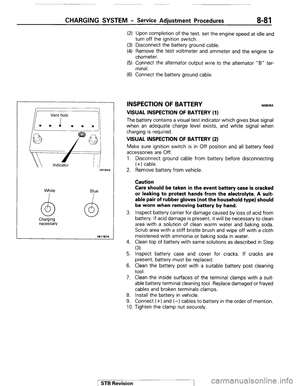
INSPECTION OF BATTERY NOBEIBA
VISUAL INSPECTION OF BATTERY (1)
The batten/ contains a visual test indicator which gives blue signal
when an adequate charge level exists, and white signal when
charging is required.
VISUAL INSPECTION OF BAlTERY (2)
Make sure ignition switch is in Off position and all battery feed
accessories are Off.
1. Disconnect ground cable from battery before disconnecting
(+) cable.
5. Inspect battery case and cover for cracks. If cracks are
present, battery must be replaced.
6. Clean the battery post with a suitable battery post cleaning
tool.
7. Clean the inside surfaces of the terminal clamps with a suit-
able battery terminal cleaning tool. Replace damaged or frayed
cables and broken terminals clamps.
8. Install the battery in vehicle.
9. Connect (+) and (-) cables to battery in the order of mention.
10. Tighten the clamp nut securely.
1 STB Revision
Page 102 of 284
8-82 CHARGING SYSTEM - Service Adjustment Procedures
BATTERY CHARGING NOEEICDZ
Caution
When batteries are being charged, an explosive gas forms
beneath the cover of each cell. Do not smoke near batteries
on charge or which have recently been charged. Do not
break live circuits at the terminals of the batteries on
charge. A spark will occur where the live circuit is broken.
Keep all open flames away from the battery.
Battery electrolyte temperature may temporarily be allowed to
rise to 55°C (131°F). Increase of electrolyte temperature above
55°C (131°F) is harmful to the battery, causing deformation of
battery cell, decrease in life of battery, etc.
CHARGE RATE
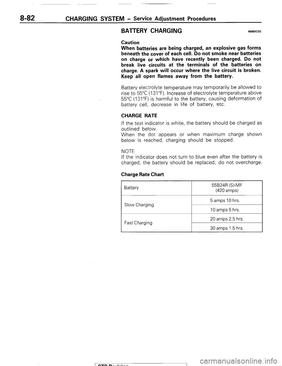
If the test indicator is white, the battery should be charged as
outlined below.
When the dot appears or when maximum charge shown
below is reached, charging should be stopped.
NOTE
If the indicator does not turn to blue even after the battery is
charged, the battery should be replaced; do not overcharge.
Charge Rate Chart
Battery 55B24R (S)-MF
(420 amps)
Slow Charging
Fast Charging 20 amps 2.5 hrs.
30 amps 1.5 hrs.
/ STB Revision
Page 131 of 284
IGNITION SYSTEM - Service Adjustment Procedures 8-111
SERVICE ADJUSTMENT PROCEDURES
CHECKING IGNITION TIMING NOEGIBA
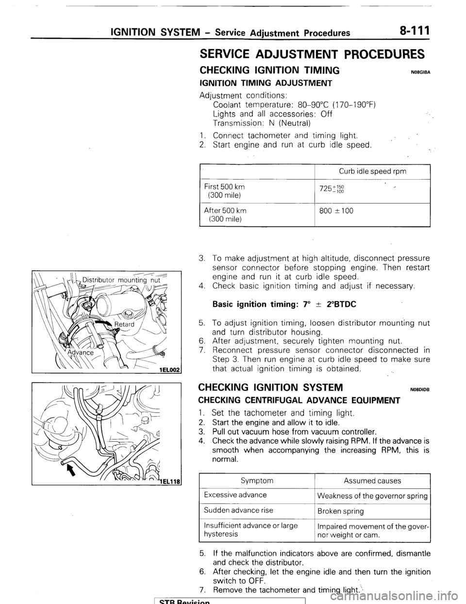
IGNITION TIMING ADJUSTMENT
Adjustment conditions:
Coolant temperature: 80-90°C (170-I 90°F)
Lights and all accessories: Off
Transmission: N (Neutral)
1. Connect tachometer and timing light.
2. Start eng.ine and run at curb idle speed.
I
Curb idle speed rpm
First 500 km
(300 mile)
After 500 km
(300 mile)
725';;;
800 ?I00 3. To make adjustment at high altitude, disconnect pressure
sensor connector before stopping engine. Then restart
engine and run it at curb idle speed.
4. Check basic ignition timing and adjust if necessary.
Basic ignition timing: 7” + 2”BTDC 5. To adjust ignition timing, loosen distributor mounting nut
and turn distributor housing.
6. After adjustment, securely tighten mounting nut.
7. Reconnect pressure sensor connector disconnected in
Step 3. Then run engine at curb idle speed to make sure
that actual ignition timing is obtained.
. .
CHECKING IGNITION SYSTEM NOBDIDB
CHECKING CENTRIFUGAL ADVANCE EQUIPMENT 1.
Set the tachometer and timing light.
2. Start the engine and allow it to idle.
3. Pull out vacuum hose from vacuum controller.
4. Check the advance while slowly raising RPM. If the advance is
smooth when accompanying the increasing RPM, this is
normal.
Symptom Assumed causes
Excessive advance
Weakness of the governor spring
Sudden advance rise
Broken spring
Insufficient advance or large
Impaired movement of the gover-
hysteresis
nor weight or cam.
5. If the malfunction indicators above are confirmed, dismantle
and check the distributor.
6. After checking, let the engine idle and then turn the ignition
switch to OFF.
7. Remove the tachometer and timing light.‘.
1 STB Revision
Page 132 of 284
8-112 IGNITION SYSTEM - Service Adjustment Procedures
CHECKING NEGATIVE PRESSURE ADVANCE EQUIPMENT
1. Set the timing light.
2. Start the engine and allow it to idle.
3. Pull out the vacuum hose from vacuum controller and attach
vacuum pump to nipple.
4. Check the advance while slowly applying negative pressure to
the vacuum pump. If the advance is smooth when accompa-
nying the increase in negative pressure, this is normal.
Secondary cable
~~
Primaw 6-8 mm
Cylinder
block
cable ’ (.24-.31 in.) 5ELO45 1
Spark plug
5ELO46
Iefective insula
5ELO47
/
Symptom
Excessive advances
Sudden advance rise
Insufficient advance or large
hysteresis
No advance Assumed causes
Weakness of vacuum controller
spring
Broken spring
Impaired movement of breaker
base
Broken diaphragm
5. If the malfunction indicators above are confirmed, dismantle
and check the distributor.
6. Allow the engine to idle and then turn the ignition switch to
OFF.
7. Remove the vacuum pump and attach the vacuum hose to the
vacuum controller nipple.
8. Remove the timing light.
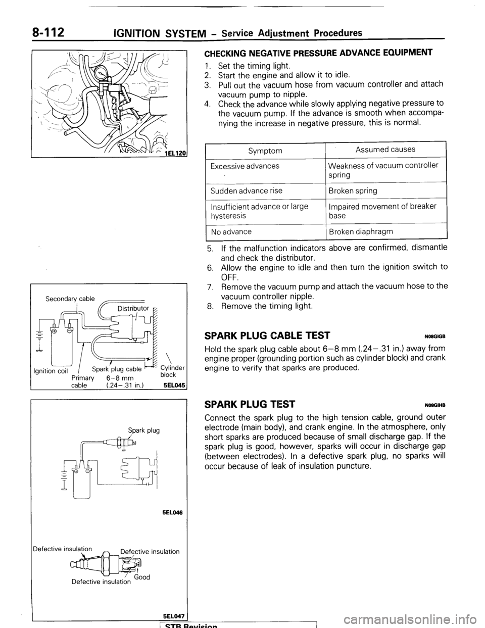
SPARK PLUG CABLE TEST NWGIGB
Hold the spark plug cable about 6-8 mm (.24-.31 in.) away from
engine proper (grounding portion such as cylinder block) and crank
engine to verify that sparks are produced.
SPARK PLUG TIEST NOUGIHB
Connect the spark plug to the high tension cable, ground outer
electrode (main body), and crank engine. In the atmosphere, only
short sparks are produced because of small discharge gap. If the
spark plug is good, however, sparks will occur in discharge gap
(between electrodes). In a defective spark plug, no sparks will
occur because of leak of insulation puncture.
fvision
I
Page 135 of 284
IGNITION SYSTEM - Ignition Svstem 8-115
Good No good
721017
72T06t
16W947
SERVICE POINTS OF REMOVAL
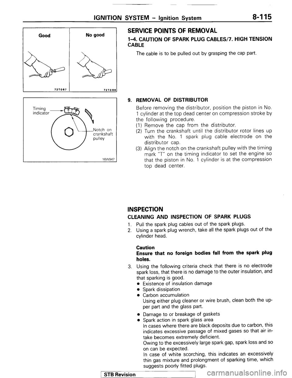
l-4. CAUTION OF SPARK PLUG CABLES17. HIGH TENSION
CABLE
The cable is to be pulled out by grasping the cap part.
9. REMOVAL OF DISTRIBUTOR
Before removing the distributor, position the piston in No.
1 cylinder at the top dead center on compression stroke by
the following procedure.
(1) Remove the cap from the distributor.
(2) Turn the crankshaft until the distributor rotor lines up
with the No. 1 spark plug cable electrode on the
distributor cap.
(3) Align the notch on the crankshaft pulley with the timing
mark “T” on the timing indicator to set the engine
SO
that the piston in No. 1 cylinder is at the compression
top dead center.
INSPECTION
CLEANING AND INSPECTION OF SPARK PLUGS
1. Pull the spark plug cables out of the spark plugs.
2. Using a spark plug wrench, take all the spark plugs out of the
cylinder head.
Caution
Ensure that no foreign bodies fall from the spark plug
holes.
3. Using the following criteria check that there is no electrode
spark loss, that there is no damage to the outer insulation, and
that sparking is good.
l Existence of insulation damage
l Spark dissipation
l Carbon accumulation
Using either plug cleaner or wire brush, clean both the up-
per part and the glass part.
l Damage to or breakage of gaskets
l Spark action in spark glass area
In cases where there are black deposits due to carbon, this
indicates excessive passage of mixed gases so that air in-
take becomes extremely deficient.
Owing to the excessively large spark gap, spark loss and so
on can be expected.
In case of white scorching, this indicates an excessively
thin gas mixture and prolongment of sparking time, which
suggests poorly fitted plugs.
/ STB Revision
1
Page 137 of 284
IGNITION SYSTEM-Ignition System 8417
Notch on
crankshaft
pulley
Stud 2
SERVICE POINTS OF INSTALLATION
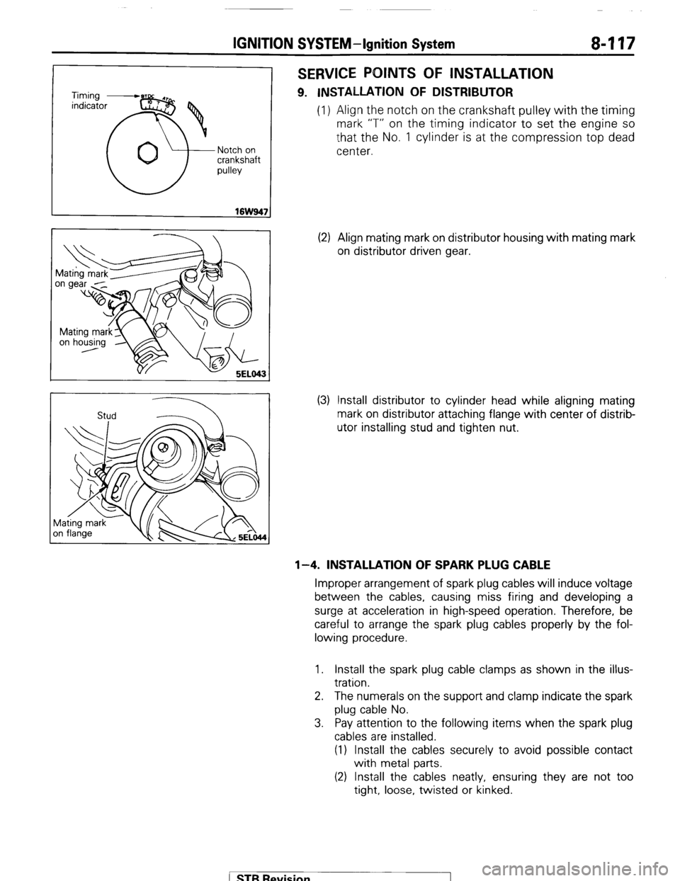
9. INSTALLATION OF DISTRIBUTOR
(1) Align the notch on the crankshaft pulley with the timing
mark “T” on the timing indicator to set the engine so
that the No. 1 cylinder is at the compression top dead
center.
(2) Align mating mark on distributor housing with mating mark
on distributor driven gear.
(3) Install distributor to cylinder head while aligning mating
mark on distributor attaching flange with center of distrib-
utor installing stud and tighten nut.
l-4. INSTALLATION OF SPARK PLUG CABLE
Improper arrangement of spark plug cables will induce voltage
between the cables, causing miss firing and developing a
surge at acceleration in high-speed operation. Therefore, be
careful to arrange the spark plug cables properly by the fol-
lowing procedure.
1. Install the spark plug cable clamps as shown in the illus-
tration.
2. The numerals on the support and clamp indicate the spark
plug cable No.
3. Pay attention to the following items when the spark plug
cables are installed.
(1) Install the cables securely to avoid possible contact
with metal parts.
(2) Install the cables neatly, ensuring they are not too
tight, loose, twisted or kinked.
( STB Revision
Page 151 of 284
METERS AND GAUGES - Service Adiustment Procedures 8-131
r
(harness side) 16W834
Stopper (upper)
FUEL GAUGE SIMPLE TEST NOEHICE
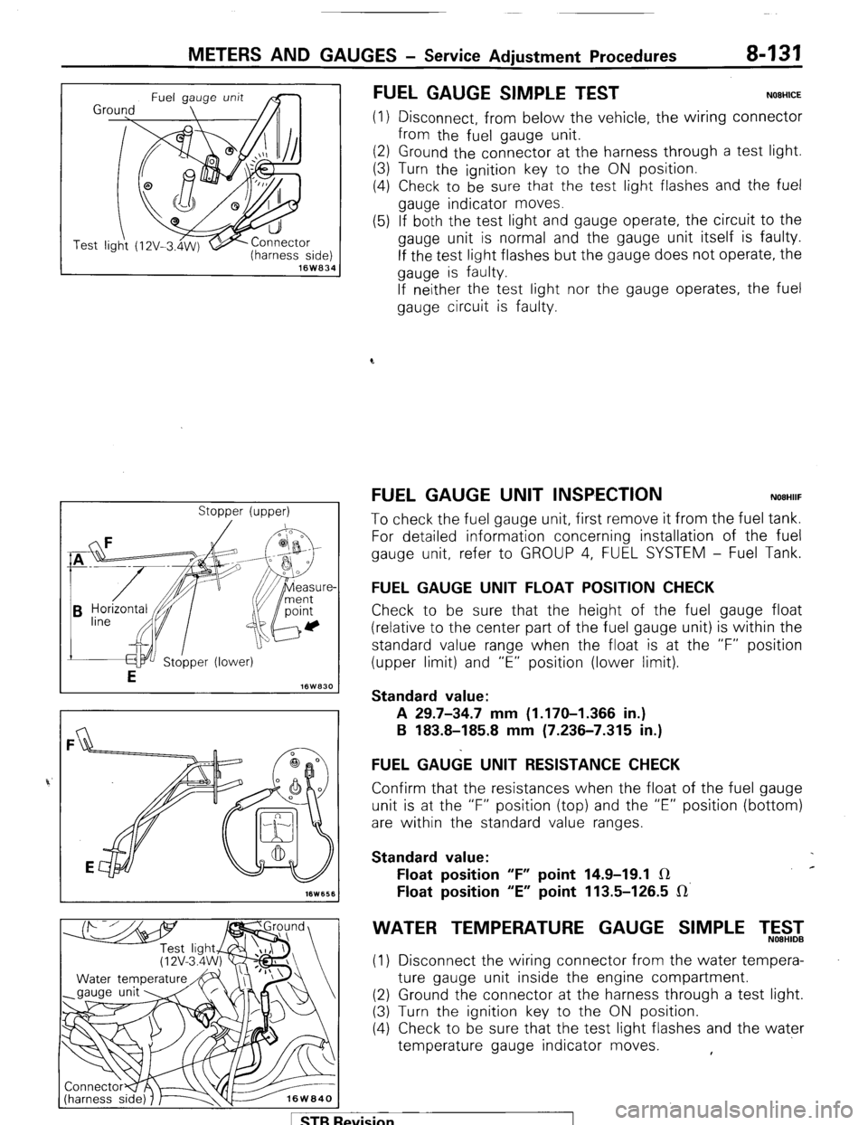
(1) Disconnect, from below the vehicle, the wiring connector
from the fuel gauge unit.
(2) Ground the connector at the harness through a test light.
(3) Turn the ignition key to the ON position.
(4) Check to be
sure that the test light flashes and the fuel
gauge indicator moves.
(5) If both the test light and gauge operate, the circuit to the
gauge unit is normal and the gauge unit itself is faulty.
If the test light flashes but the gauge does not operate, the
gauge is faulty.
If neither the test light nor the gauge operates, the fuel
gauge circuit is faulty.
FUEL GAUGE UNIT INSPECTION NOEHIIF
To check the fuel gauge unit, first remove it from the fuel tank.
For detailed information concerning installation of the fuel
gauge unit, refer to GROUP 4, FUEL SYSTEM - Fuel Tank.
FUEL GAUGE UNIT FLOAT POSITION CHECK
Check to be sure that the height of the fuel gauge float
(relative to the center part of the fuel gauge unit) is within the
standard value range when the float is at the “F” position
(upper limit) and “E” position (lower limit).
Standard value:
A 29.7-34.7 mm (1.170-I .366 in.)
B 183.8-185.8 mm (7.236-7.315 in.)
FUEL GA&E UNIT RESISTANCE CHECK
Confirm that the resistances when the float of the fuel gauge
unit is at the “F” position (top) and the “E” position (bottom)
are within the standard value ranges.
Standard value:
Float position “F” point 14.9-19.1 IR c
Float position “E” point 113.5-126.5 IR’
WATER TEMPERATURE GAUGE SIMPLE T,5$2
(1) Disconnect the wiring connector from the water tempera-
ture gauge unit inside the engine compartment.
(2) Ground the connector at the harness through a test light.
(3) Turn the ignition key to the ON position.
(4) Check to be sure that the test light flashes and the water
temperature gauge indicator moves. ,
1 STB Revision
Page 152 of 284
8-132 METERS AND GAUGES - Service Adjustment Procedures
(5) If both the test light and gauge operate, the circuit to the
gauge unit is normal and the gauge unit itself is faulty.
If the test light flashes but the gauge does not operate, the
gauge is faulty.
If 1 neither the test light nor the gauge operates, the water
temperature gauge circuit is faulty.
Se
VVATER TEMPERATURE GAUGE UNIT ONSPEC-
TION
NOBHIKD
To check the water temperature gauge unit, first remove it
from the intake manifold.
For detailed information concerning installation of the water
temperature gauge unit, refer to GROUP 11, INTAKE AND
EXHAUST SYSTEM - Intake Manifold.
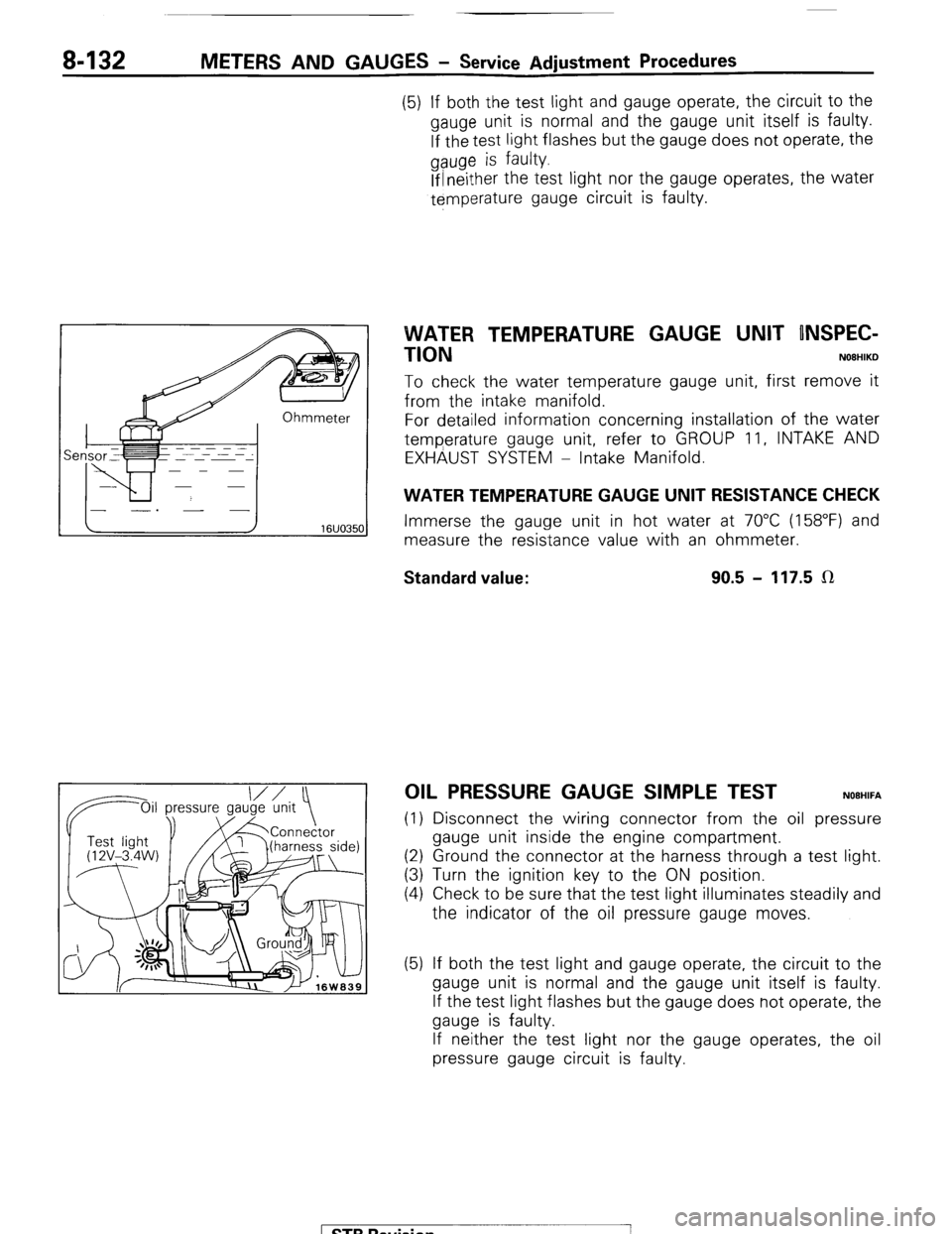
WATER TEMPERATURE GAUGE UNIT RESISTANCE CHECK
Immerse the gauge unit in hot water at 70°C (158°F) and
measure the resistance value with an ohmmeter.
Standard value: 90.5 - 117.5 LR
OIL PRESSURE GAUGE SIMPLE TEST NOEHIFA
(1) Disconnect the wiring connector from the oil pressure
gauge unit inside the engine compartment.
(2) Ground the connector at the harness through a test light.
(3) Turn the ignition key to the ON position.
(4) Check to be sure that the test light illuminates steadily and
the indicator of the oil pressure gauge moves.
(5) If both the test light and gauge operate, the circuit to the
gauge unit is normal and the gauge unit itself is faulty.
If the test light flashes but the gauge does not operate, the
gauge is faulty.
If neither the test light nor the gauge operates, the oil
pressure gauge circuit is faulty.
1 STB Revision
-7