Solenoid MITSUBISHI MONTERO 1987 1.G Workshop Manual
[x] Cancel search | Manufacturer: MITSUBISHI, Model Year: 1987, Model line: MONTERO, Model: MITSUBISHI MONTERO 1987 1.GPages: 284, PDF Size: 14.74 MB
Page 48 of 284
8-28 WIRING HARNESS - Engine Compartment
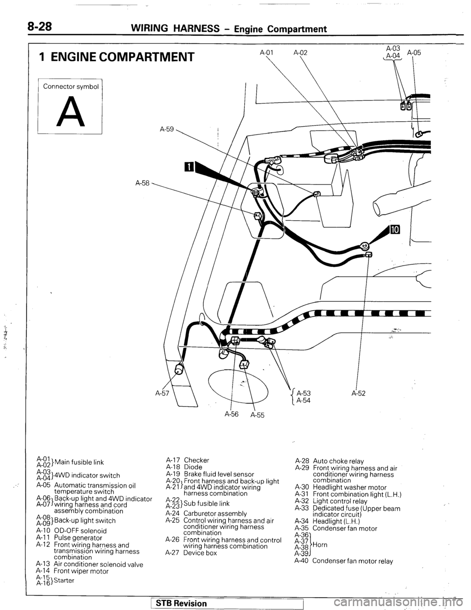
1 ENGINE COMPARTMENT
Connector symbol
A
;:::I Main fusible link
;:::I 4WD indicator switch
A-05 Automatic transmission oil
temperature switch
A-06 Back-u light and 4WD indicator
A-07)wiring f!arness and cord
assembly combination
;:g> Back-up light switch
A-l 0 OD-OFF solenoid
A-l 1 Pulse generator
A-l 2 Front wiring harness and
transmission wiring harness
combination
A-13 Air conditioner solenoid valve
A-l 4 Front wiper motor A-
A156
A-55
A-l 7 Checker
A-18 Diode
A-19 Brake fluid level sensor
A-20 Front harness and back-up light
A-21 land 4WD indicator wiring
harness combination
it;;> Sub fusible link
A-24 Carburetor assembly
A-25 Control wiring harness and air
conditioner wiring harness
combination
A-26 Front wiring harness and control
wiring harness combination
A-27 Device box A-53 A-52
A-54
A-28 Auto choke relay
A-29 Front wiring harness and air
conditioner wiring harness
combination
A-30 Headlight washer motor
A-31 Front combination light (L.H.)
A-32 Light control relay
A-33 Dedicated fuse (Upper beam
indicator circuit)
A-34 Headlight (L.H.)
A-35 Condenser fan motor
A-40 Condenser fan motor relay
1 STB Revision
Page 58 of 284
8-38 WIRING HARNESS - Feed Back Carburetor Circuit
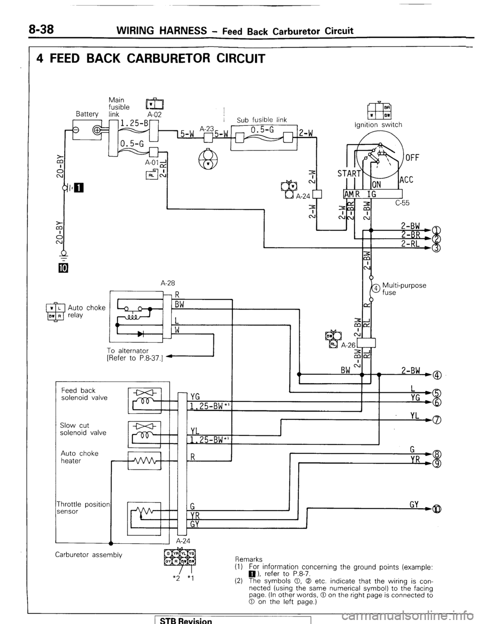
4 FEED BACK CARBURETOR CIRCUIT
Main
fusible ’ m
Battery link A-02 j
-1.25-B- i Sub fusible link
I L uA-2i
I:
a h
W r
efl
EEI W BW
Ignition switch
A-28
qi
--I
zix
c:
-26c-1
ziE2
BW ".
I w 2-BW wQ
To alternator
[Refer to P.8.37.1 1 I
r Feed back
solenoid valve
c YG
1.25-BW"'
I
I yL
,0
P Slow cut
solenoid valve YL
1.25-BW*'
Auto choke
heater
-hrottle position
iensor
A-24 1
Carburetor assembly
Remarks
(1) For information concerning the ground points (example:
0). refer to P.8-7.
(2) The symbols 0, 0 etc. indicate that the wiring is con-
nected (using the same numerical symbol) to the facing
page. (In other words, 0 on the right page is connected to
0 on the left page.)
STB Revision
Page 59 of 284
WIRING HARNESS - Feed Back Carburetor Circuit 8-39
Ignition
coil
) _ ,E3
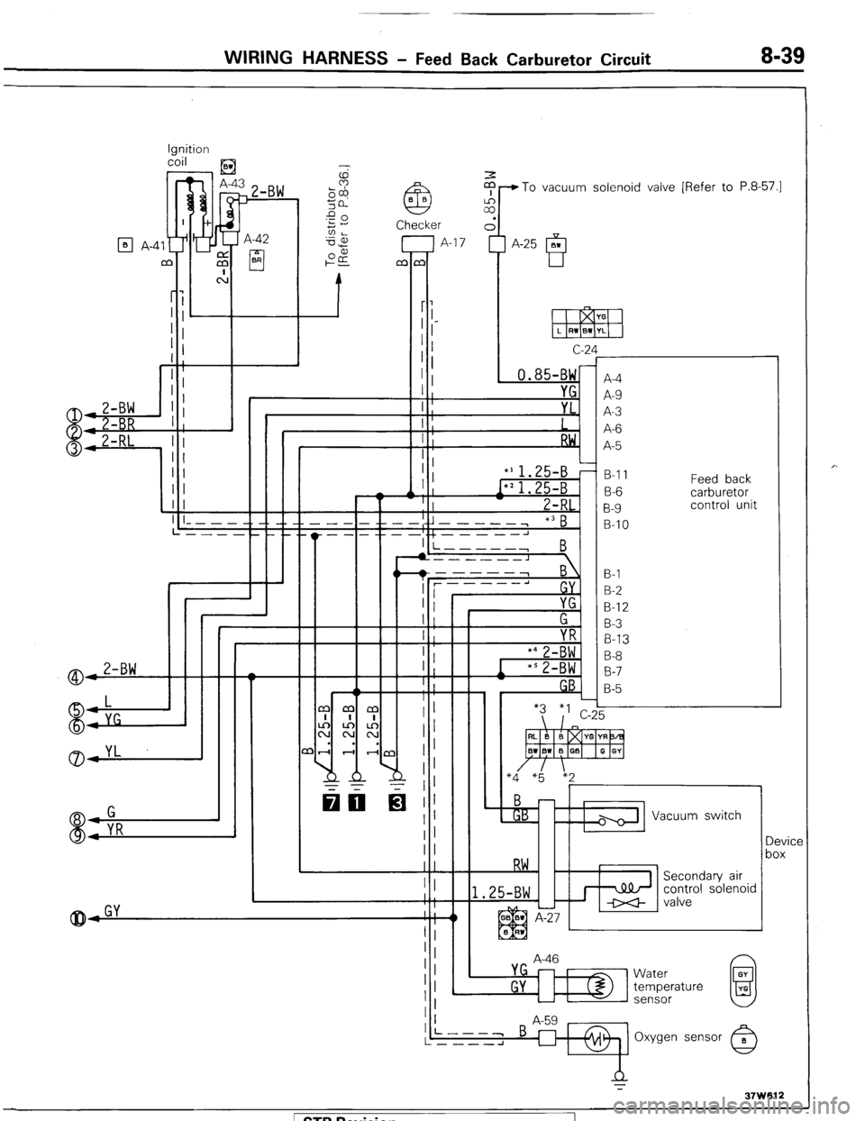
$-To vacuum solenoid valve [Refer to P.8-57.1
7 A-42
cl BR
q A-4
c-2
, 0.85-BW
I YG
I ;
I : YL.
I
I ;
RW,
I :
‘A
f
r
A-4
A-9
A-3
A-6
A-5
B-l 1
B-6
B-9
B-IO Feed back
carburetor
control unit
I
II
II
(I I
1 I ! ! I I- - - - -. -_ __ __
L---- __._._
I +L----J I i-----,
B
B-l
B-2
B-l 2
B-3
B-13
B-8
B-7
B-5
A-46 Vacuum switch
Device
box
control solenoid
L
L
Water
temperature
sensor 1 STB Revision
Page 60 of 284
8-40 WIRING HARNESS - Layout of Components WC)
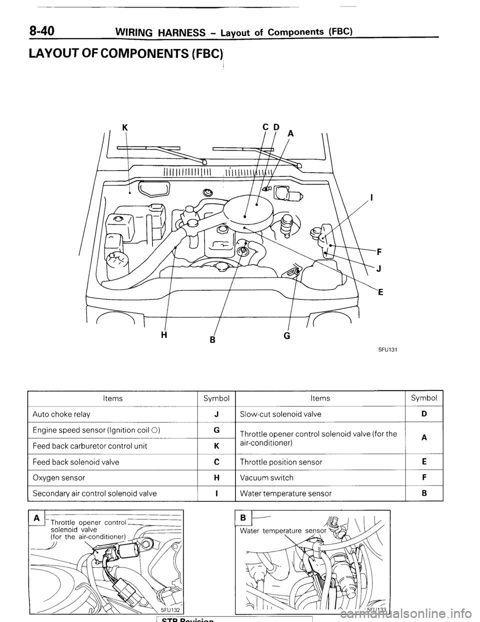
LAYOUT OFCOMPONENJS [FBC)
CD
II A
5FU131
Items
Symbol Items Symbol
Auto choke relay J Slow-cut solenoid valve D
Engine speed sensor (Ignition coil 0)
Feed back carburetor control unit G
Throttle opener control solenoid valve (for the
A
K air-conditioner)
Feed back solenoid valve
I
C Throttle position sensor
I E
Oxygen sensor
I H Vacuum switch
I F
Secondary air control solenoid valve
I I 1 Water temperature sensor
I B
Throttle opener contr
solenoid valve
Page 63 of 284
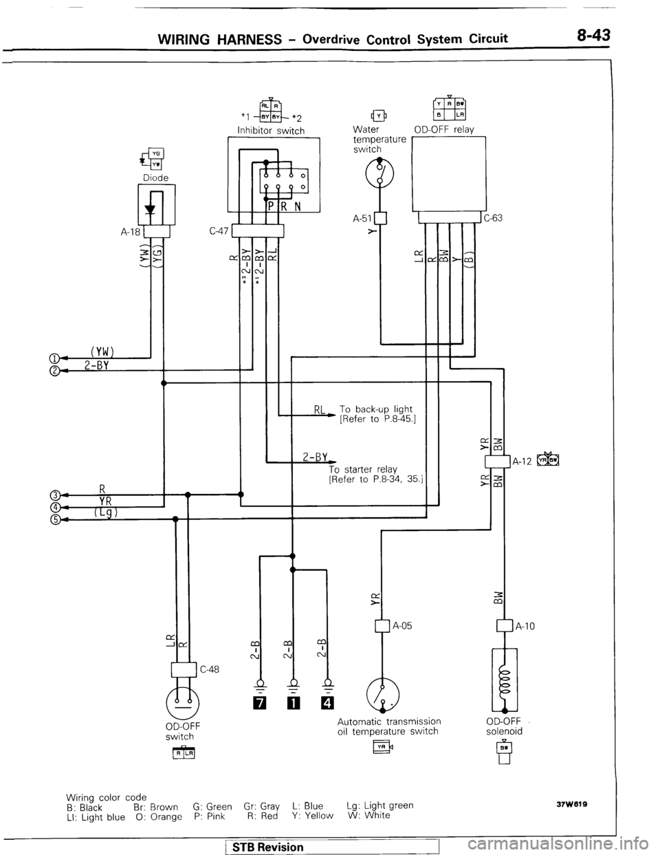
WIRING HARNESS - Overdrive Control System Circuit 8-43
*I
Inhibitor switch
I Water OD-OFF relav 1 temperature r -63 C-
RL To back-up light
) [Refer to P.8-45.1 2-BY
t
To starter relay
[Refer to P.8-34, 35.1 IA-12 @@ 3
4
VRR
9 5
I t
L
1
r
A-05 -10
switch
[RILRI Automatic transmission
oil temperature switch
llR)3 OD-OFF
solenoid
Wiring color code
B: Black Br: Brown G: Green G;; ;ZJ L: Blue Lg: Light green
LI: Light blue 0: Orange P: Pink Y: Yellow W: White
37w019
1 STB Revision
Page 77 of 284
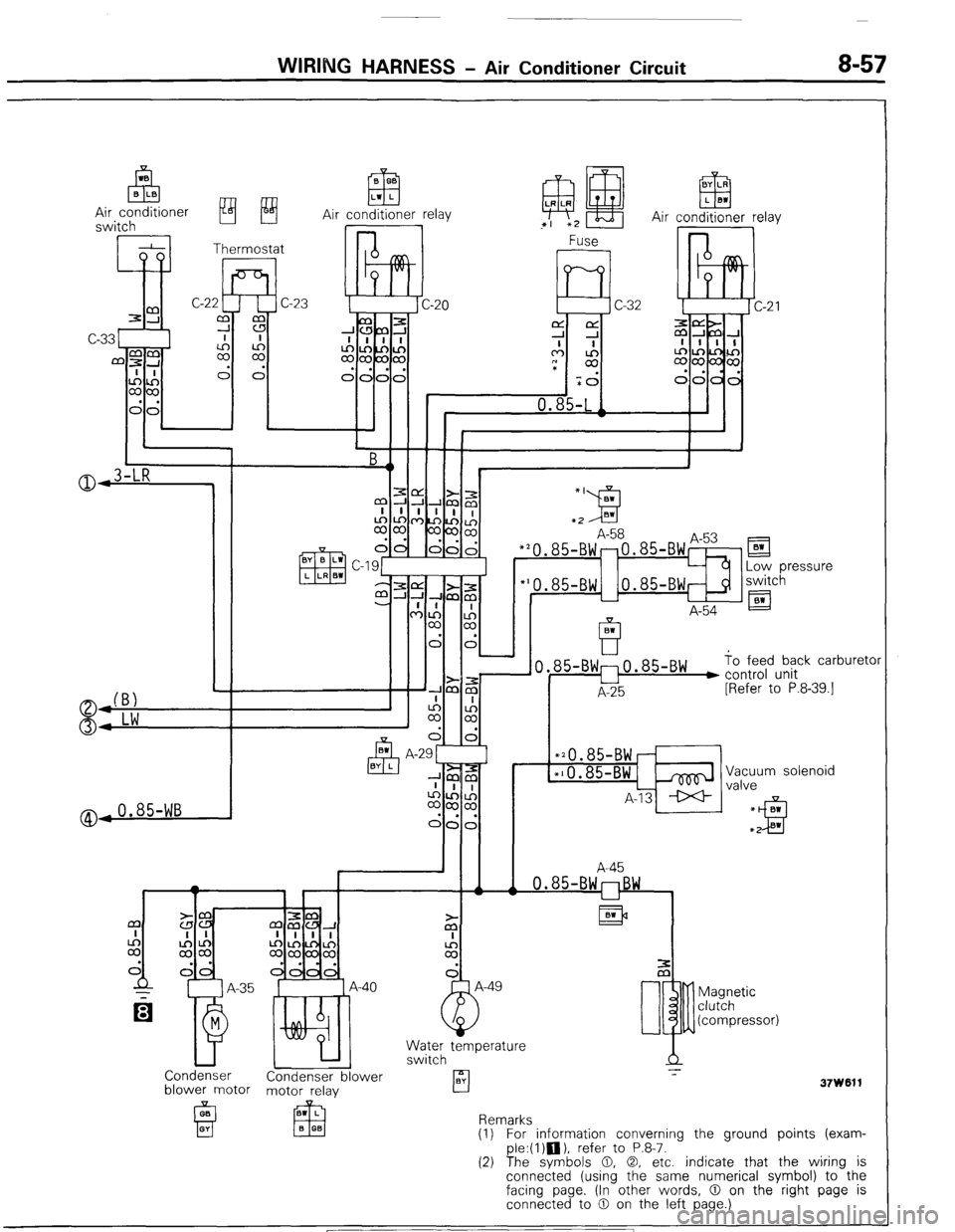
WIRING HARNESS - Air Conditioner Circuit 8-57
0
(Bl
0: Lw
@,0.85-WB B 0.3
ElFI Lvf L
Air conditioner relay I @ H ‘I *2 Air :on!$!er rela
85-Bw:o.85-Bw ) to feed back carburetor
u control unit
A-25 [Refer to P.8-39.1
l 20.85-BWr
l 10.85-BWL&
A-13 * Vacuum solenoid
valve
A-45
0.85-BWnBW
Is*la
Magnetic
clutch
(compressor)
U
Water temperature
switch
Condenser
Condenser blower -I-
BY
blower motor motor relay rl
37W611
Remarks
(1) For information converning the ground points (exam-
ple:(l)n), refer to P.8-7.
(2) The svmbols 0, 0, etc. indicate that the wiring is
connedted (using the same numerical symbol) to-the
facing page. (In other words, 0 on the right page is
connected to 0 on the left page.) ) STB Revision
Page 111 of 284
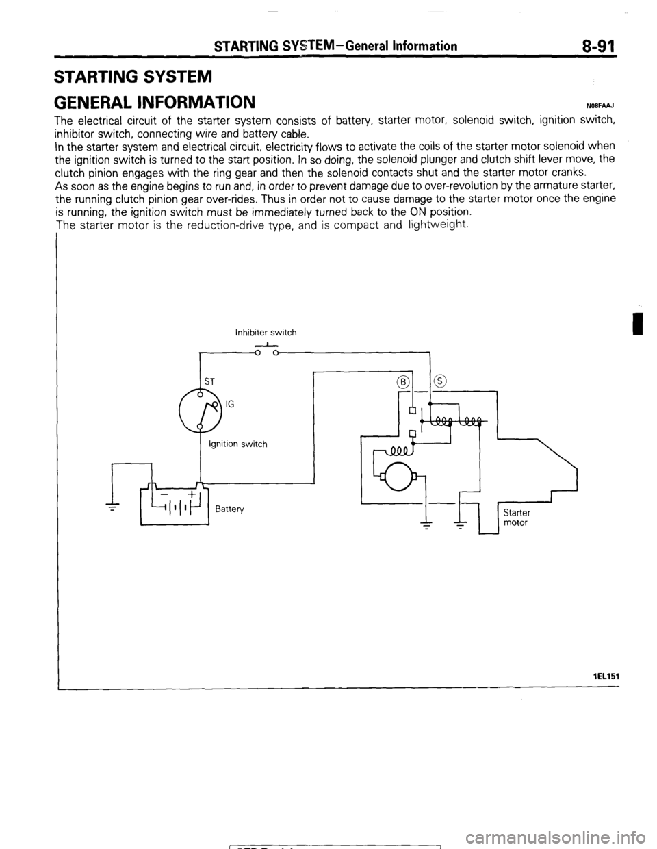
STARTING SYSTEM-General Information 8-91
STARTING SYSTEM
GENERAL INFORMATION
NOBFAAJ
The electrical circuit of the starter system consists of battery, starter motor, solenoid switch, ignition switch,
inhibitor switch, connecting wire and battery cable.
In the starter system and electrical circuit, electricity flows to activate the coils of the starter motor solenoid when
the ignition switch is turned to the start position. In so doing, the solenoid plunger and clutch shift lever move, the
clutch pinion engages with the ring gear and then the solenoid contacts shut and the starter motor cranks.
As soon as the engine begins to run and, in order to prevent damage due to over-revolution by the armature starter,
the running clutch pinion gear over-rides, Thus in order not to cause damage to the starter motor once the engine
is running, the ignition switch must be immediately turned back to the ON position.
The starter motor is the reduction-drive type, and is compact and lightweight.
Inhibiter switch
-
I lEL151
1 STB Revision
Page 263 of 284
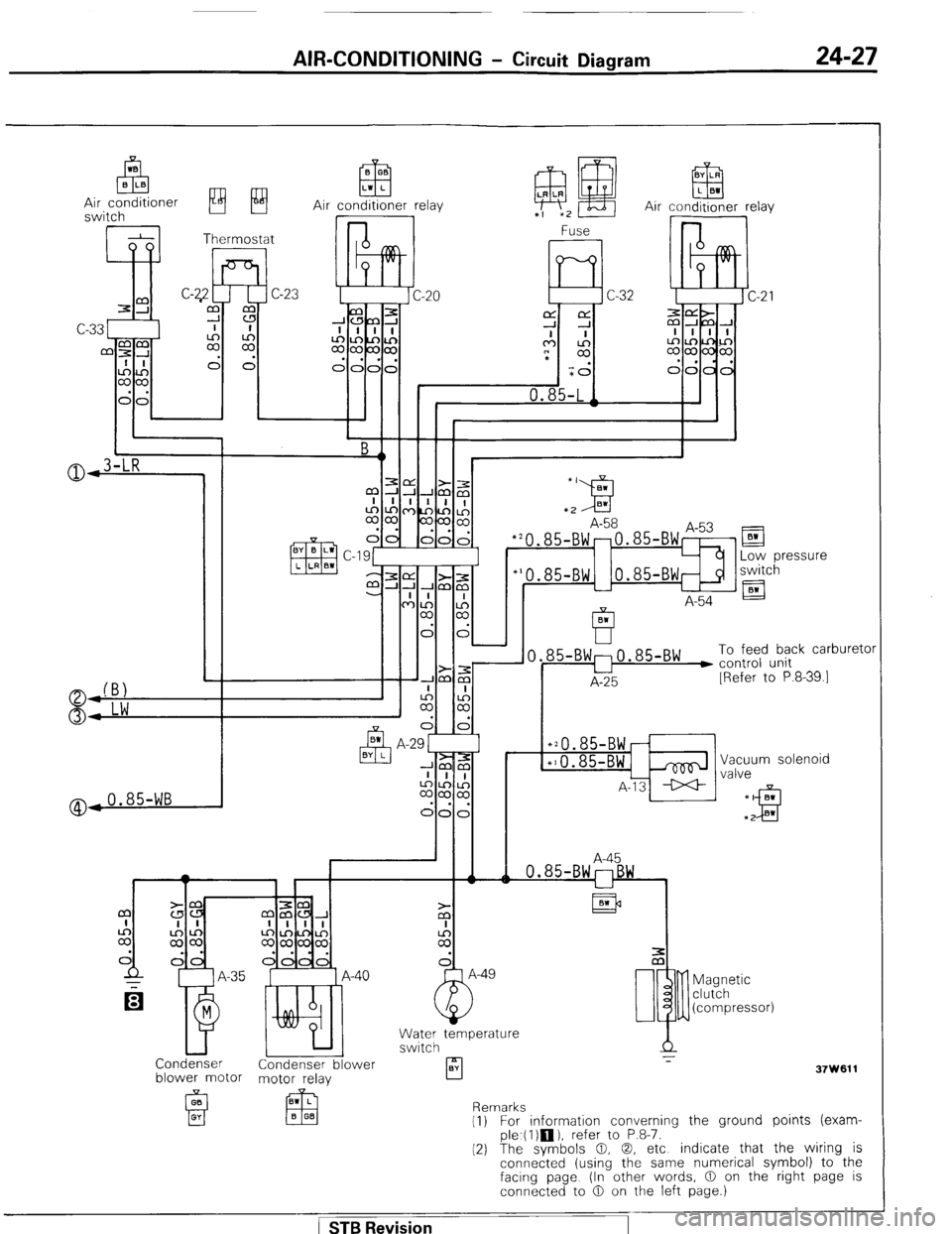
AIR-CONDITIONING - Circuit Diagram 24-27
Air conditioner relay
@,0.85-WB
El
Low pressure
switch
A-54 El
85-BW:0.85-BW ) To feed back carburetc
u control unit
A-25 [Refer to P.8-39.1
*20.85-BWr
*10.85-BWi& Vacuum solenoid
A-13 ++ valve
A-45
Condenser Condenser blower
blower motor motor relay
A
rl z-
BY
37W611 Magnetic
clutch
(compressor)
Remarks
(1) For information converning the ground points (exam-
ple.(l)m), refer to P.8-7.
(2) The symbols 0, 0, etc indicate that the wiring is
connected (using the same numerical symbol) to the
facing page (In other words, 0 on the right page is
connected to 0 on the left page.)
( STB Revision