headlights MITSUBISHI MONTERO 1987 1.G Workshop Manual
[x] Cancel search | Manufacturer: MITSUBISHI, Model Year: 1987, Model line: MONTERO, Model: MITSUBISHI MONTERO 1987 1.GPages: 284, PDF Size: 14.74 MB
Page 97 of 284
CHARGING SYSTEM - Service Adjustment Procedures 8-77
SERVICE ADJUSTMENT PROCEDUREswmAB
lEL15I
INSPECTION OF THE CHARGING SYSTEM
VOLTAGE DROP TEST OF ALTERNATOR OUTPUT WIRE
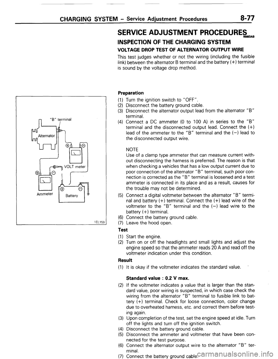
This test judges whether or not the wiring (including the fusible
link) between the alternator B terminal and the battery (+) terminal
is sound by the voltage drop method.
Preparation
(1) Turn the ignition switch to “OFF”.
(2) Disconnect the battery ground cable.
(3) Disconnect the alternator output lead from the alternator “B”
terminal.
(4) Connect a DC ammeter (0 to 100 A) in series to the “B”
terminal and the disconnected output lead. Connect the (+)
lead of the ammeter to the “B” terminal and the (-) lead to
the disconnected output wire.
NOTE
Use of a clamp type ammeter that can measure current with-
out disconnecting the harness is preferred. The reason is that
when checking a vehicles that has a low output current due to
poor connection of the alternator “B” terminal, such poor con-
nection is corrected as the “B” terminal is loosened and a test
ammeter is connected in its place and as a result, causes for
the trouble may not be determined.
(5) Connect a digital voltmeter between the alternator “B” termi-
nal and battery (+) terminal. Connect the (+) lead wire of the
voltmeter to the “B” terminal and the (-) lead wire to the
battery (+) terminal.
(6) Connect the battery ground cable.
(7) Leave the hood open.
Test
(1) Start the engine.
(2) Turn on or off the headlights and small lights and adjust the
engine speed so that the ammeter reads 20 A and read off the
voltmeter indication under this condition.
Result
(1) It is okay if the voltmeter indicates the standard value. ’
Standard value : 0.2 V max.
(2) If the voltmeter indicates a value that is larger than the stan-
dard value, poor wiring is suspected, in which case check the
wiring from the alternator “B” terminal to fusible link to bat-
tery (+) terminal. Check for loose connection, color change
due to overheated harness, etc. and correct them before test-
ing again.
(3) Upon completion of the test, set the engine speed at idle. Turn
off the lights and turn off the ignition switch.
(4) Disconnect the battery ground cable.
(5) Disconnect the ammeter and voltmeter that have been con-
nected for the test purpose.
(6) Connect the alternator output wire to the alternator “B” ter-
minal.
(7) Connect the battery ground cable.
( STB Revision
Page 99 of 284
CHARGING SYSTEM - Service Adjustment Procedures 8-79
Result
(1) The ammeter reading must be higher than the limit value. If it
is lower but the alternator output wire is normal, remove the
alternator from the vehicle and check it.
Limit value : 31 A min.
Caution
1. The nominal output current value is shown on the
nameplate affixed to the alternator body.
2. The output current value changes with the electrical
load and the temperature of the alternator itself.
Therefore, the nominal output current may not be ob-
tained if the vehicle electrical load at the time of test is
small. In such a case, keep the headlights on to cause
discharge of the battery or use lights of another vehi-
cle as a load to increase the electrical load. The nom-
inal output current may not be obtained if the temper-
ature of the alternator itself or abmient temperature is
too high. In such a case, reduce the temperature be-
fore testing again.
(2) Upon completion of the output current test, lower the engine
speed to the idle speed and turn off the ignition switch.
(3) Disconnect the battery ground cable.
(4) Remove the test ammeter and voltmeter and the engine ta-
chometer.
(5) connect the alternator output wire to the alternator “B” ter-
minal.
(6) Connect the battery ground cable.
REGULATED VOLTAGE TEST
The purpose of this test is to check that the electronic voltage
regulator controls the voltage correctly.
Preparation
(1) Prior to the test, check the following items and correct if nec-
essary.
(a) Check the battery installed on the vehicle to see that it is
fully charged. For battery checking method, see “BAT-
TERY”.
(b) Check the alternator drive belt tension. For belt tension
check, see “GROUP 7 COOLING - Service Adjustment
Procedures”.
(2) Turn the ignition switch to “OFF”.
(3) Disconnect the battery ground cable.
(4) Connect a digital voltmeter between the “S” terminal of the
alternator and ground. Connect the (+) lead of the voltmeter to
the “S” terminal of the alternator, inserting from the wire side
of the 2-way connector and connect the (-1 lead to sound
ground or battery (-) terminal.
1 ST6 Revision
Page 161 of 284
METERS AND GAUGES - Indicators and Warning Lights 8-141
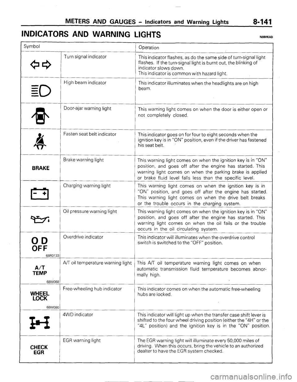
INDICATORS AND WARNING
LIGHTS
Symbol
Operation
Turn signal indicator
+e3 This indicator flashes, as do the same side of turn-signal light
flashes. If the turn-signal light is burnt out, the blinking of
indicator slows down.
This indicator is common with hazard light.
0
High beam indicator
- This indicator illuminates when the headlights are on high
= beam.
=
* Door-ajar warning light
This warning light comes on when the door is either open or
not completely closed.
4 Fasten seat belt indicator
This indicator goes on for four to eight seconds when the
ignition key is in “ON” position, even if the driver has fastened
his seat belt.
BRAKE
Brake warning light
This warning light comes on when the ignition key is in “ON”
position, and goes off after the engine has started. This
warning light comes on when the parking brake is applied
or brake fluid level falls less than the specific level.
III Charging warning light This warning light comes on when the ignition key is in
- + “ON” position, and goes off after the engine has started.
This warning light comes on when the drive belt breaks
or the trouble occurs in the charging system.
Oil pressure warning light This warning light comes on when the ignition key is in “ON”
P position, and goes off after the engine has started. This
warning light comes on when the oil fails or the trouble
occurs in the oil circulating system.
00
Overdrive indicator
This indicator will illuminates when the overdrive control
OFF
switch is switched to the “OFF” position.
68R0133
A/T
A/T oil temperature warning light This A/T oil temperature warning light comes on when
TEMP automatic transmission fluid temperature becomes abnor-
mally high.
68WO68
Free-wheeling hub indicator
YEL This indicator comes on when the automatic free-wheeling
hubs are locked.
68WO80
z4 4WD indicator This indicator will light up when the transfer case shift lever is
shifted to the four wheel driving position (either the “4H” or the
“4L” position) and the ignition key is in the “ON” position.
CHECK
EGR
EGR warning light The EGR warning light will illuminate every 50,000 miles of
driving. When this occurs, bring the vehicle to an authorized
dealter to have the EGR system checked.
) STB Revision
Page 165 of 284
LIGHTING SYSTEM - Special tools / Troubleshooting
SPECIAL TOOLS
Tool (Number and name)
MB990784
Ornament remover Use
Removal of hazard
warning switch
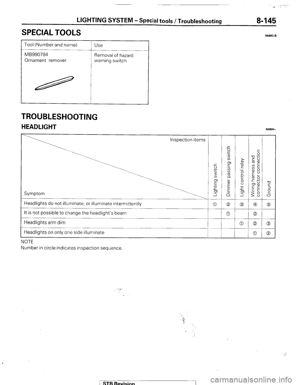
TROUBLESHOOTING
HEADLIGHT
Inspection items
1 Symptom
Headlights do not illuminate, or illuminate intermittently
It is not possible to change the headlight’s beam
Headlights arm dim
Headlights on only one side illuminate
NOTE
Number in circle indicates inspection sequence. 0
0
0
NOIIG-B
-0
K
2
t
0
0
0 ( STB Revision
Page 177 of 284
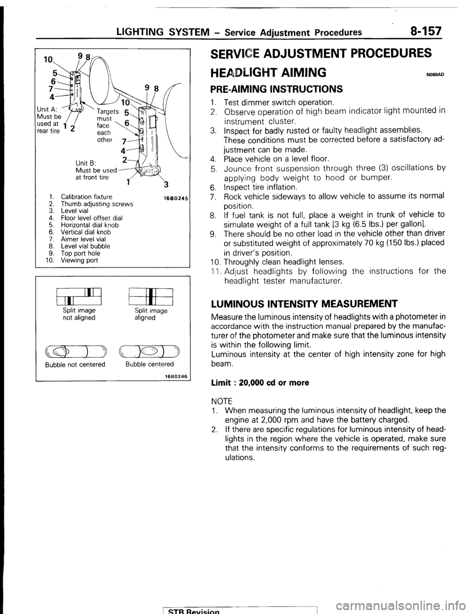
LIGHTING SYSTEM - Service Adjustment Procedures 8-157
Must be used J;it A:
I ‘w ‘Targets
1. Calibration fixture
2. Thumb adjusting screws
3. Level vial
4. Floor level offset dial
5. Horizontal dial knob
6. Vertical dial knob
7. Aimer level vial
8. Level vial bubble
9. Top port hole
10. Viewing port
1660245
Split image
not aligned Split image
aligned
Bubble not centered Bubble centered
1660246
E ADJUSTMENT PROCEDURES
T AIMING
PRE-AIMING INSTRUCTIONS 1. Test dimmer switch operation.
2. Observe operation of high beam indicator light
mounted in instrument cluster.
3. Inspect for badly rusted or faulty headlight assemblies.
These conditions must be corrected before a satisfactory ad-
justment can be made.
4. Place vehicle on a level floor.
5. Jounce front suspension through three (3) oscillations by
applying body weight to hood or bumper.
6. Inspect tire inflation.
7. Rock vehicle sideways to allow vehicle to assume its normal
position.
8. If fuel tank is not full, place a weight in trunk of vehicle to
simulate weight of a full tank [3 kg (6.5 Ibs.) per gallon].
9. There should be no other load in the vehicle other than driver
or substituted weight of approximately 70 kg (150 Ibs.) placed
in driver’s position.
10. Throughly clean headlight lenses.
11. Adjust headlights by following the instructions for the
headlight tester manufacturer.
LUMINOUS INTENSITY MEASUREMENT Measure the luminous intensity of headlights with a photometer in
accordance with the instruction manual prepared by the manufac-
turer of the photometer and make sure that the luminous intensity
is within the following limit.
Luminous intensity at the center of high intensity zone for high
beam.
Limit : 20,000 cd or more NOTE
1. When measuring the luminous intensity of headlight, keep the
engine at 2,000 rpm and have the battery charged.
2. If there are specific regulations for luminous intensity of head-
lights in the region where the vehicle is operated, make sure
that the intensity conforms to the requirements of such reg-
ulations.
pTB Revision