lock MITSUBISHI MONTERO 1987 1.G Workshop Manual
[x] Cancel search | Manufacturer: MITSUBISHI, Model Year: 1987, Model line: MONTERO, Model: MITSUBISHI MONTERO 1987 1.GPages: 284, PDF Size: 14.74 MB
Page 6 of 284
6 INTRODUCTION - Vehicle Identification
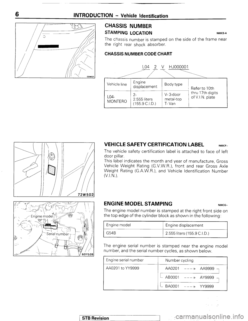
CHASSIS NUMBER
STAMPING LOCATION NOOCE-A
The chassis number is stamped on the side of the frame near
the right rear shock absorber.
CHASSIS NUMBER CODE CHART
LO4 2 V HJOOOOOl
A’ i’
,
VEHICLE SAFETY CERTIFICATION LABEL NOOCF-
The vehicle safety certification label is attached to face of left
door pillar.
This label indicates the month and year of manufacture, Gross
Vehicle Weight Rating (G.V.W.R.), front and rear Gross Axle
Weight Rating (G.A.W.R.), and Vehicle Identification Number
(V.I.N.).
ENGINE MODEL STAMPING NOOCG-
The engine model number is stamped at the right front side on
the top edge of the cylinder block as shown in the following:
1 Engine model
1 Engine displacement
1 2.555 liters (155.9 C.I.D.)
The engine serial number is stamped near the engine model
number, and the serial number cycles, as shown below
Engine serial number
AA020’toYY= Number cycling
/ STB Revision
--I f ,. ..-.
j ‘. .,
Page 8 of 284
8 INTRODUCTION - Precautions Before Service
r oorn,
FOOOl;
FOOOl8
PRECAUTIONS BEFORE SERVICE
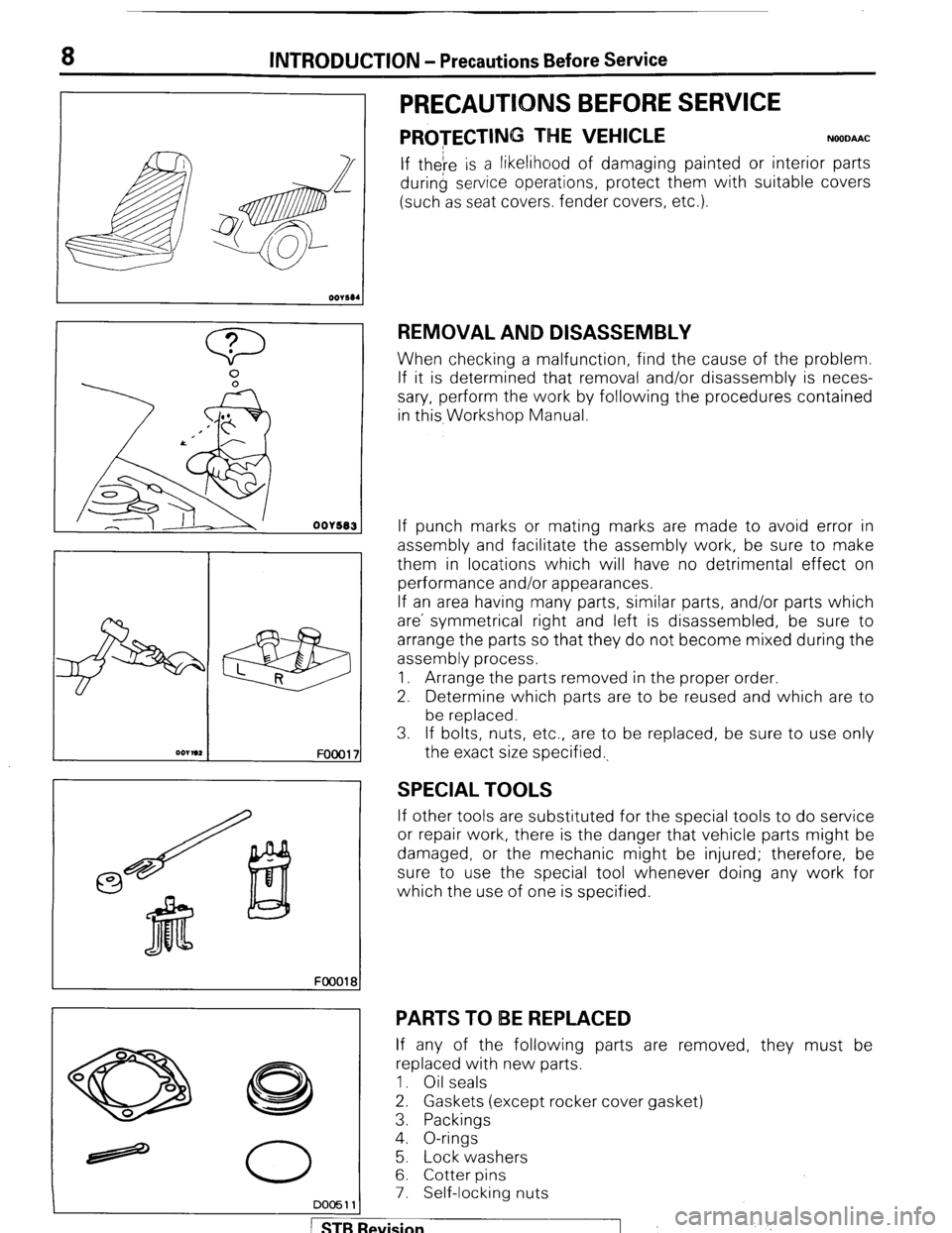
PROTECTIN” THE VEHICLE NOODAAC
If theIre is a likelihood of damaging painted or interior parts
during service operations, protect them with suitable covers
(such as seat covers. fender covers, etc.).
REMOVAL AND DISASSEMBLY
When checking a malfunction, find the cause of the problem.
If it is determined that removal and/or disassembly is neces-
sary, perform the work by following the procedures contained
in this, Workshop Manual.
If punch marks or mating marks are made to avoid error in
assembly and facilitate the assembly work, be sure to make
them in locations which will have no detrimental effect on
performance and/or appearances.
If an area having many parts, similar parts, and/or parts which
are’ symmetrical right and left is disassembled, be sure to
arrange the parts so that they do not become mixed during the
assembly process.
1. Arrange the parts removed in the proper order.
2. Determine which parts are to be reused and which are to
be replaced.
3. If bolts, nuts, etc., are to be replaced, be sure to use only
the exact size specified.,
SPECIAL TOOLS
If other tools are substituted for the special tools to do service
or repair work, there is the danger that vehicle parts might be
damaged, or the mechanic might be injured; therefore, be
sure to use the special tool whenever doing any work for
which the use of one is specified.
PARTS TO IBE REPLACED
If any of the following parts are removed, they must be
replaced with new parts.
1. Oil seals
2. Gaskets (except rocker cover gasket)
3. Packings
4. O-rings
5. Lock washers
6. Cotter pins
7. Self-locking nuts
DO05111
STB Revision ,j .’
Page 15 of 284
INTRODUCTION - Towing and Hoisting
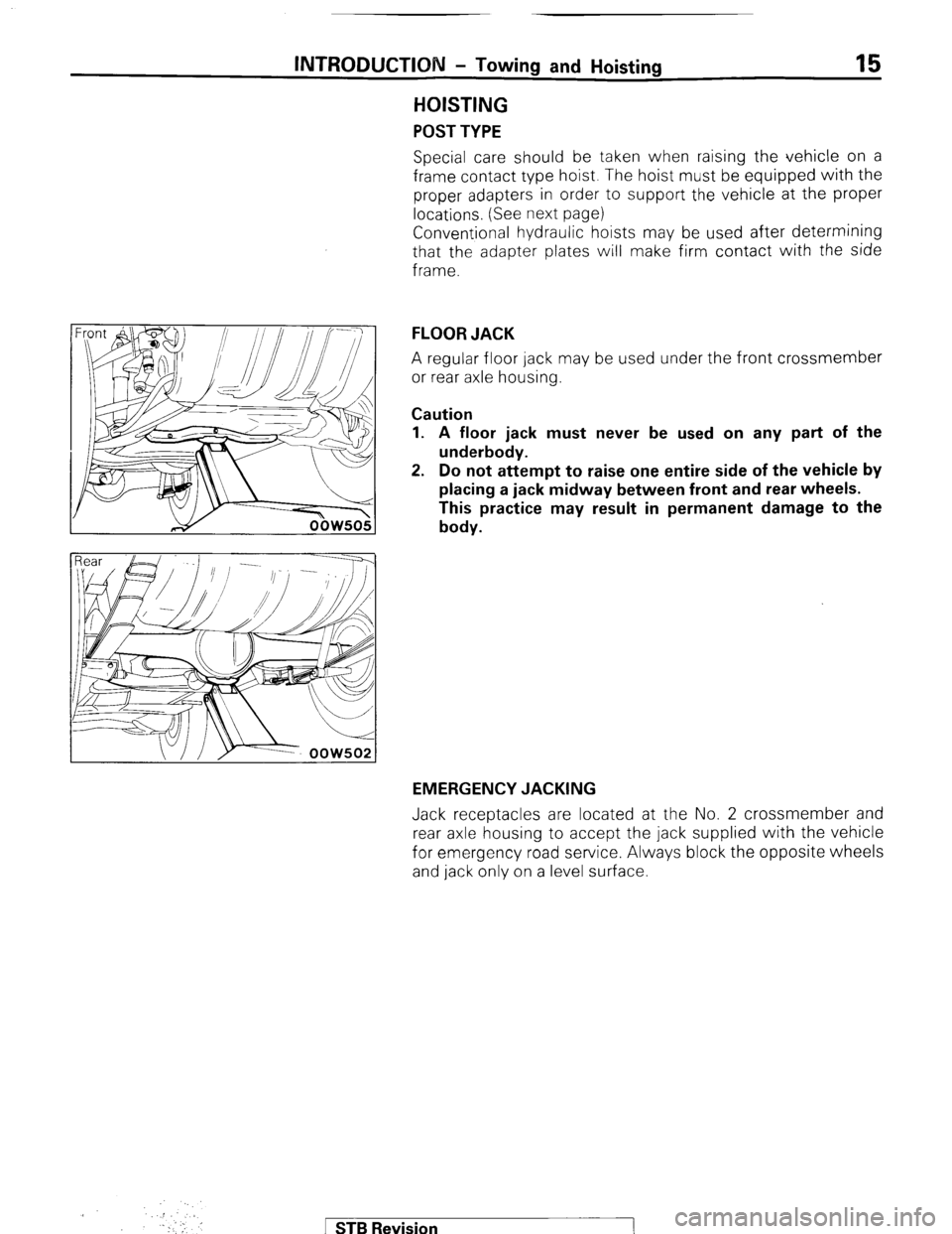
HOISTING
POST TYPE
15
Special care should be taken when raising the vehicle on a
frame contact type hoist. The hoist must be equipped with the
proper adapters in order to support the vehicle at the proper
locations. (See next page)
Conventional hydraulic hoists may be used after determining
that the adapter plates will make firm contact with the side
frame.
FLOOR JACK
A regular floor jack may be used under the front crossmember
or rear axle housing.
Caution
1. A floor jack must never be used on any part of the
underbody.
2. Do not attempt to raise one entire side of the vehicle by
placing a jack midway between front and rear wheels.
This practice may result in permanent damage to the
body.
EMERGENCY JACKING
Jack receptacles are located at the No. 2 crossmember and
rear axle housing to accept the jack supplied with the vehicle
for emergency road service. Always block the opposite wheels
and jack only on a level surface.
.::
. Y!’ ,,. I
.I
‘.
1 STB Revision
Page 21 of 284
8-1
ELECTRICAL
CONTENTS
NOBAA-
ACCESSORY ......................................................
188
Cigarette Lighter ............................................
,190
Clock ...............................................................
,191
AUDIO SYSTEM ................................................
.192
AUTOMATIC FREE-WHEELING HUB
INDICATOR SYSTEM ........................................
208
Automatic Free-wheeling Hub
Indicator Control Unit
..................................... ,216
Pulse Generator ..............................................
215
BACK DOOR WINDOW DEFOGGER
................ .203
Defogger switch ............................................
,206
Printed Heater Lines
...................................... ,207
CHARGING SYSTEM .........................................
71
Alternator ........................................................
83
Service Adjustment Procedures
..................... 77
Battery Charging ........................................
82
Inspection of Battery ..................................
81
Output Current Test ...................................
78
Regulated Voltage Test ..............................
79
Voltage Drop Test of Alternator Output
Wire ............................................................
77
ELECTRICAL SYSTEM PARTS LOCATION
...... 2
Diode ...............................................................
5
Fusible Link and Fuse
..................................... 6
Grounding .......................................................
7
Relay and Control Unit ....................................
2
Sensor .............................................................
4
HORN ..................................................................
184
Horn Switch
.................................................... 187
IGNITION SYSTEM ............................................
105
Ignition Switch
................................................ 122
Ignition System ...............................................
1 14
Service Adjustment Procedures
.................... .l 1 1
Checking Ignition System
..........................
11 1
Checking Ignition Timing
...........................
11 1
Spark Plug Cable Test
................................
1 12
Spark Plug Test
.......................................... 1 12 INSPECTION OF HARNESS CONNECTOR ...... 9
Check for Improper Engagement of
Terminal .......................................................... 9
Continuity and Voltage Test for Connector .... 9
Engaging and Disengaging of Connector
Terminal ..........................................................
9
LIGHTING SYSTEM ........................................... 143
Column Switch
................................ .
.............. .I59
Dimmer Control Switch
................................. .I62
Hazard Warning Switch
................................. .I61
Headlight ........................................................ ,158
Service Adjustment Procedures
.................... .I57
Headlight Aiming .......................................
157
METERS AND GAUGES .................................... 123
Service Adjustment Procedures
.................... .I30
Fuel Gauge Simple Test ................................. .I31
Fuel Gauge Unit Inspection ........................... .I31
Oil Pressure Gauge Simple Test
.................... .I32
Oil Pressure Gauge Unit Simple Test
............ ,132
Speedometer Inspection
............................... .I30
Tachometer Inspection .................................. ,130
Voltage Meter Simple Test
............................ .I33
Water Temperature Gauge Simple Test
....... ..I3 1
Water Temperature Gauge Unit Inspection
. ..I3 2
STARTING SYSTEM .......................................... 91
Starter Motor ............ ....................................... 97
WIPER AND WASHER SYSTEM
....................... .163
WIRING HARNESS ............................................ 13
Centralized Junction ....................................... 69
Circuit Diagram ............................................... 34
Configuration Diagram .................................... 27
How to Read Wiring Diagrams ....................... 20
Troubleshooting .............................................. 13
Page 37 of 284
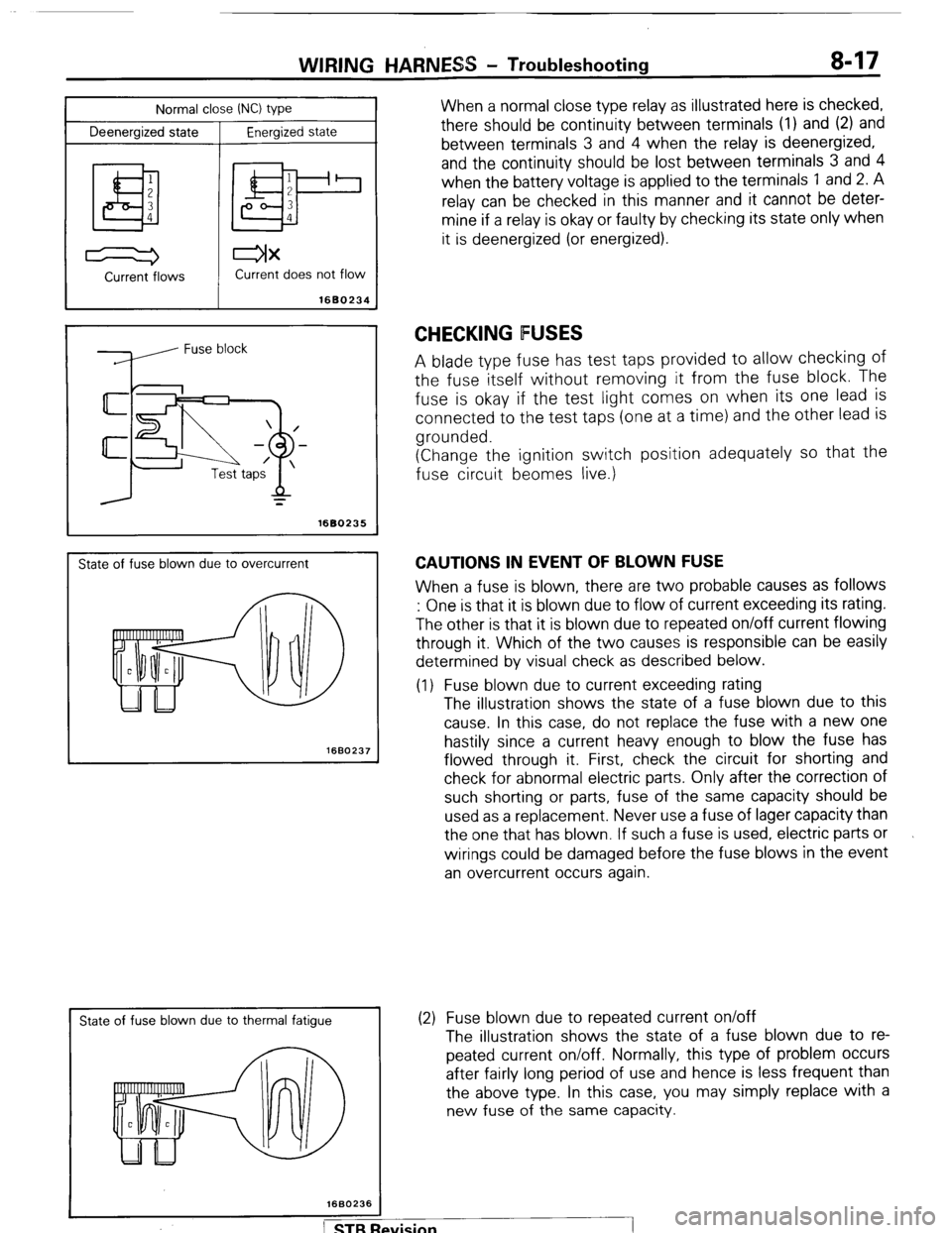
Normal close INC) type
Deenergized state
Energized state
I
WIRING HARNESS - Troubleshooting 8-17
When a normal close type relay as illustrated here is checked,
there should be continuity between terminals (1) and (2) and
between terminals 3 and 4 when the relay is deenergized,
and the continuity should be lost between terminals 3 and 4
when the battery voltage is applied to the terminals 1 and 2. A
relay can be checked in this manner and it cannot be deter-
mine if a relay is okay or faulty by checking its state only when
it is deenergized (or energized).
Current -flows Current does not flow
1680234
=
1680235
State of fuse blown due to overcurrent
1660237
I
State of fuse blown due to thermal fatigue
CHECKING FUSES
A blade type fuse has test taps provided to allow checking of
the fuse itself without removing it from the fuse block. The
fuse is okay if the test light comes on when its one lead is
connected to the test taps (one at a time) and the other lead is
grounded.
(Change the ignition switch position adequately so that the
fuse circuit beomes live.)
CAUTIONS IN EVENT OF BLOWN FUSE
When a fuse is blown, there are two probable causes as follows
: One is that it is blown due to flow of current exceeding its rating.
The other is that it is blown due to repeated on/off current flowing
through it. Which of the two causes is responsible can be easily
determined by visual check as described below.
(1) Fuse blown due to current exceeding rating
The illustration shows the state of a fuse blown due to this
cause. In this case, do not replace the fuse with a new one
hastily since a current heavy enough to blow the fuse has
flowed through it. First, check the circuit for shorting and
check for abnormal electric parts. Only after the correction of
such shorting or parts, fuse of the same capacity should be
used as a replacement. Never use a fuse of lager capacity than
the one that has blown. If such a fuse is used, electric parts or
wirings could be damaged before the fuse blows in the event
an overcurrent occurs again.
(2) Fuse blown due to repeated current on/off
The illustration shows the state of a fuse blown due to re-
peated current on/off. Normally, this type of problem occurs
after fairly long period of use and hence is less frequent than
the above type. In this case, you may simply replace with a
new fuse of the same capacity.
Page 39 of 284
WIRING HARNESS - Troubleshooting 8-19
Test
light Power supply
Fuse block
(remove fuse)
r’TJ Switch
?
Illumination light
4, 1680241
Self power test light Switch
ON
OFF
1680242
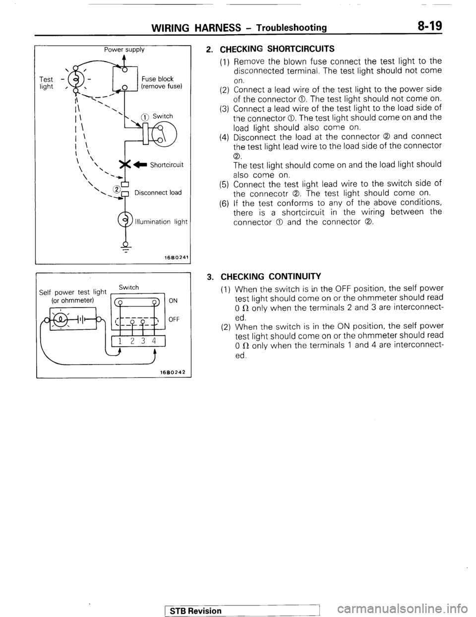
2. CHECKING SHORTCIRCUITS
(1) Remove the blown fuse connect the test light to the
disconnected terminal. The test light should not come
on.
(2) Connect a lead wire of the test light to the power side
of the connector 0. The test light should not come on.
(3) Connect a lead wire of the test light to the load side of
the connector 0. The test light should come on and the
load light should also come on.
(4) Disconnect the load at the connector 0 and connect
the test light lead wire to the load side of the connector
CD.
The test light should come on and the load light should
also come on.
(5) Connect the test light lead wire to the switch side of
the connecotr 0. The test light should come on.
(6) If the test conforms to any of the above conditions,
there is a shortcircuit in the wiring between the
connector 0 and the connector 0.
3. CHECKING CONTINUITY
(I) When the switch is in the OFF position, the self power
test light should come on or the ohmmeter should read
0 R only when the terminals 2 and 3 are interconnect-
ed.
(2) When the switch is in the ON position, the self power
test light should come on or the ohmmeter should read
0 LR only when the terminals 1 and 4 are interconnect-
ed.
) STB Revision
Page 51 of 284
WIRING HARNESS - Interior and Frame 8-31
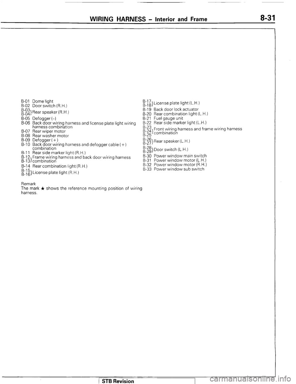
B-01 Dome light
B-02 Door switch (R.H.)
:::3 Rear speaker (R.H.) /&}License plate light (L.H.)
B-19 Back door lock actuator
B-20 Rear combination light (L.H.)
B-05 Defogger (-) B-21 Fuel gauge unit
B-06 Back door wiring harness and license plate light wiring B-22 Rear side marker light (L.H.)
harness combination
B-07 Rear wiper motor
B-08 Rear washer motor
B-09 Defogger (+)
B-l 0 Back door wiring harness and defogger cable (+)
combination
B-l 1 Rear side marker light (R.H.)
B-12 Frame wiring harness and back door wiring harness
B-13)combination B-23 Front wiring harness and frame wiring harness
;:g combination
E$ Rear speaker (L.H.)
:::g> Door switch (L.H.)
B-30 Power window main switch
B-31 Power window motor (L.H.)
B-14 Rear combination light (R.H.)
&z}License plate light (R.H.) B-32 Power window motor (R.H.)
B-33 Power window sub switch
Remark
The mark + shows the reference mounting position of wiring
harness.
STB Revision
Page 52 of 284
8-32 WIRING HARNESS - Instrument Panel
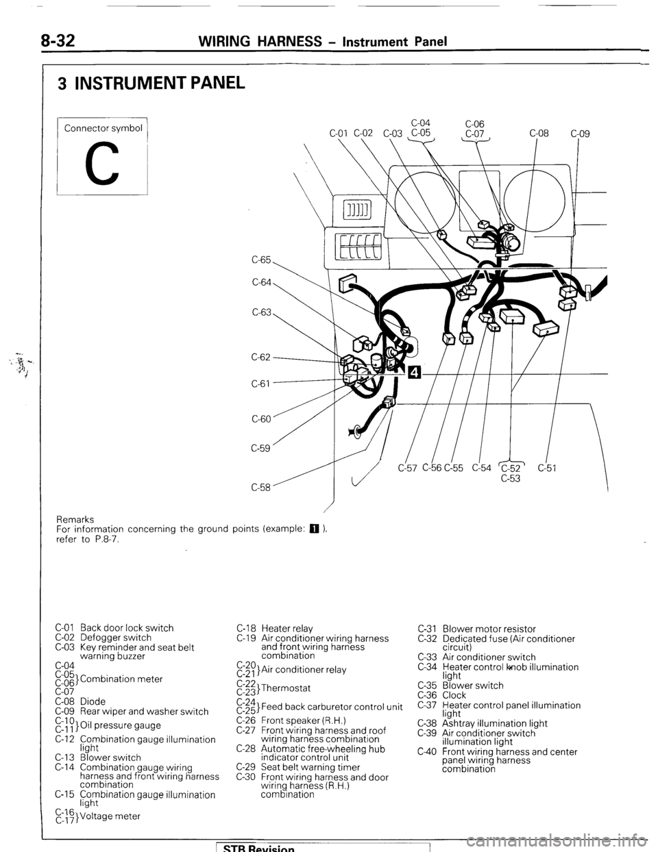
3 INSTRUMENT PANEL
Connector symbol
C
C-65 c-04
C-06
C-64
C-63
C-61
CL57 C-b6 C!55 d54 c!5
Remarks
For information concerning the ground points (example:
q ),
refer to P.8-7.
C-01 Back door lock switch
C-02 Defogger switch
C-03 Kev reminder and seat belt
warning buzzer
c-04
pi;’ Combination meter
C-08 Diode
C-09 Rear wiper and washer switch
r&~}Oil pressure gauge
C-12 f;hybination gauge illumination
C-l 3 Blower switch
C-14 Combination gauge wiring
harness and front wiring harness
combination
C-15 F;hybination gauge illumination
C,::F}Voltage meter C-l 8 Heater relay
C-l 9 Air conditioner wiring harness
and front wiring harness
combination
E:$)}Air conditioner relay C-31 Blower motor resistor
C-32 Dedicated fuse (Air conditioner
circuit)
C-33 Air conditioner switch
C-34 yl;Jer control lonob illumination
$:;;I Thermostat
$:;;I Feed back carburetor control unit
C-26 Front speaker (R.H.)
C-27 Front wiring harness and roof
wiring harness combination
C-28 Automatic free-wheeling hub
indicator control unit
C-29 Seat belt warning timer
C-30 Front wiring harness and door
wiring harness (R.H.)
combination c-35
C-36
c-37
C-38
c-39
c40
“3’ ‘. Blower switch
Clock
Heater control panel illumination
light
Ashtray illumination light
Air conditioner switch
illumination light
Front wiring harness and center
panel wiring harness
combination
[ STB Revision
Page 71 of 284
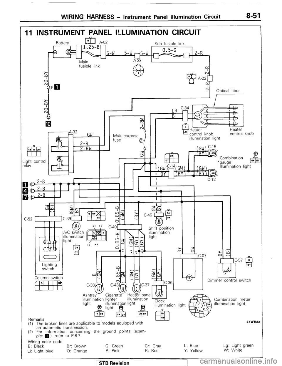
WIRING HARNESS - Instrument Panel Wumination Circuit 8-51
11 INSTRUMENT PANEL ILLUMINATION CIRCUIT
Battery
Sub fusible link
5-w 0.5-G
5-w l-75-W m 2-R - L-
Main A-23
fusible link
@L
M’ CA
A A-22
Y$lO rx
c-l
Optical fiber
I
I
Multi-purpose
fuse
0
3
a control knob
illumination light
.ight contr
clay
& 01 BY
7t Combination
gauge
Illumination ligl
c-4o1l Shift-position
lmer control switch
C-38
4
Ashtray
illumination Cigaretty Hegpane _
lighter illumination ’ I
minagn light Clock
n+ 63 illumination light Combination meter
illumination light
37w '62; (1) The broken lines are applicable to models equipped with
an automatic transmission.
(2) For information concerning the ground points (exam-
ple: 0 ), refer to P.8-7.
Wiring color code
B: Black Br: Brown G: Green Gr: Gray
LI: Light blue 0: Orange P: Pink R: Red L: Blue
Y: Yellow Lg: Light green
W: White
1 STB Revision
Page 82 of 284
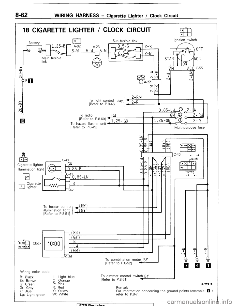
8-62 WIRING HARNESS - Cigarette Lighter / Clock Circuit
18 CIGARETTE LIGHTER / CLOCK CIRCUIT
Sub fusible link Ignition switch
r-l E-f? ‘) n
-u yn;in fusible
7-R \*I
To light control relay
[Refer to P.8-461
To radio
GW [Refer to P&601-, 3F- Pm
To hazard flasher unit4 I .LJ- G
[Refer to P.8-491
II I Multi-purpose fuse
illumination light
To heater control
illumination light
[Refer to P.8-511
Clock
CT
0: 1
h J
6
Jc-36
To combination mete& BY
[Refer to P.8-521 1
Wiring color code
B: Black LI: Light blue To dimmer control switch BY
Br: Brown 0: Orange [Refer to P.8-511 M
G: Green P: Pink
-
Gr: Gray H: Red
L: Blue Y: Yellow
Lg: Light green W: White Remark
For information concerning the ground points (example: 0 1,
refer to P.8-‘7.