relay MITSUBISHI MONTERO 1991 Workshop Manual
[x] Cancel search | Manufacturer: MITSUBISHI, Model Year: 1991, Model line: MONTERO, Model: MITSUBISHI MONTERO 1991Pages: 1333, PDF Size: 24.61 MB
Page 875 of 1333

Press "3" key or press down arrow to display CONFIGURE option
and press ENTER. Configure allows user to customize DRB-II display.
For example, If metric system is more useful, select METRIC from the
menu. All selections in CONFIGURE option remain active until user
changes selection.
SELECT VEHICLE
1) This allows the user to enter information about vehicle
being tested. Usually, this option has more than one display screen.
Use ENTER key to enter vehicle information.
2) When all information about vehicle is entered, DRB-II will
display an information summary the technician has entered. DRB-II will
show an additional option marked CONFIRM. If information is correct,
press CONFIRM. DRB-II will display MAIN MENU.
MAIN MENU
The MAIN MENU represents all diagnostic functions available.
Functions are SYSTEM TESTS, READ FAULTS, STATE DISPLAYS, ACTUATOR
TESTS and ADJUSTMENTS. SYSTEM TESTS is NOT available.
READ FAULTS
This allows technician to read fault codes stored in ECU
memory.
STATE DISPLAYS
1) This allows technician to view conditions at signal level.
The 2 types of signals are analog and digital. Analog signals are
monitored at pins corresponding to vehicle harness splices (e.g. fuel
pump relay).
2) Digital signals correspond to data transmitted by the
system controllers. Both signals are displayed in common units (e.g.
temperature). Use up and down arrow keys on DRB-II to scroll through
displays available.
3) The following ENGINE state displays are available on DRB-
II:
* Module Information - This mode allows technician to read ECU
part number and application.
* Engine Sensors - This mode allows technician to look at
various engine sensors during engine operation.
* Inputs/Outputs - This mode allows technician to read input
and output states of various switches and sensors.
* Custom Display - This screen allows technician to set up
his/her own custom display. Two custom display screens can be
programmed into DRB-II.
* Minimum/Current/Maximum - The MIN/CURRENT/MAX display shows a
history of conditions for a specific sensor. When this option
is selected, maximum, current (static) and minimum values can\
be displayed for a specific sensor. To reset sensors to a
zero value, simply press ENTER key. This display may be used
to isolate intermittent faults. The MIN/CURRENT/MAX display
allows technician to observe operation of 6 different sensor
values. Information is displayed as a 3-digit number. The
first value displayed is the minimum reading, the second
number is the current reading and third valve is the maximum
reading. Typically sensors range between 2-252. Values less
than 2 or greater than 252 will usually indicate that a
Page 876 of 1333
sensor is shorted or disconnected. Watch minimum and maximum
values to help diagnose intermittent problems.
* Monitors - This screen shows technician sensors and system
controllers which affect fuel control, spark advance, RPM and
A/C relay. There are 4 different screens available. As an
example, screen No. 1 will show: airflow sensor, O2 sensor,
battery and fuel injector. All of these inputs affect fuel
control.
Actuator Tests
This mode allows technician to actuate injectors, fuel pump,
purge control, EGR solenoid, fuel pressure solenoid and wastegate.
Adjustments
This option provides a means for erasing fault code
information stored in ECU. Follow DRB-II instructions to accomplish
this task.
DRB-II ERROR SCREENS
ERROR SCREENS
SYSTEM FAULT ROM CHECK SUM XXXX Message
Cartridge or DRB-II failure.
SYSTEM FAULT KEYBOARD FAILURE Message
Restart DRB-II. Ensure DRB-II keys are not pressed during
power up. Another possibility is DRB-II failure.
SYSTEM FAULT ROM FAILURE XXXX
DRB-II failure.
SYSTEM FAULT EEPROM FAILURE
DRB-II failure.
SYSTEM FAILURE, COMMUNICATION FAILURE, REFER TO DIAGNOSTIC
PROCEDURES Message
Perform diagnostic connector test. See DRIVEABILITY TEST No.
8 (DR-8). Failure of Mitsubishi Motor Corporation (MMC) adapter is
another possibility.
SYSTEM FAILURE NO RESPONSE FROM ADAPTER or SYSTEM FAILURE
ADAPTER REQUIRED TO DIAGNOSE WITH THIS CARTRIDGE Message
Ensure you are using a correct Mitsubishi Motor Corporation
cartridge. Failure of MMC adapter is another possibility.
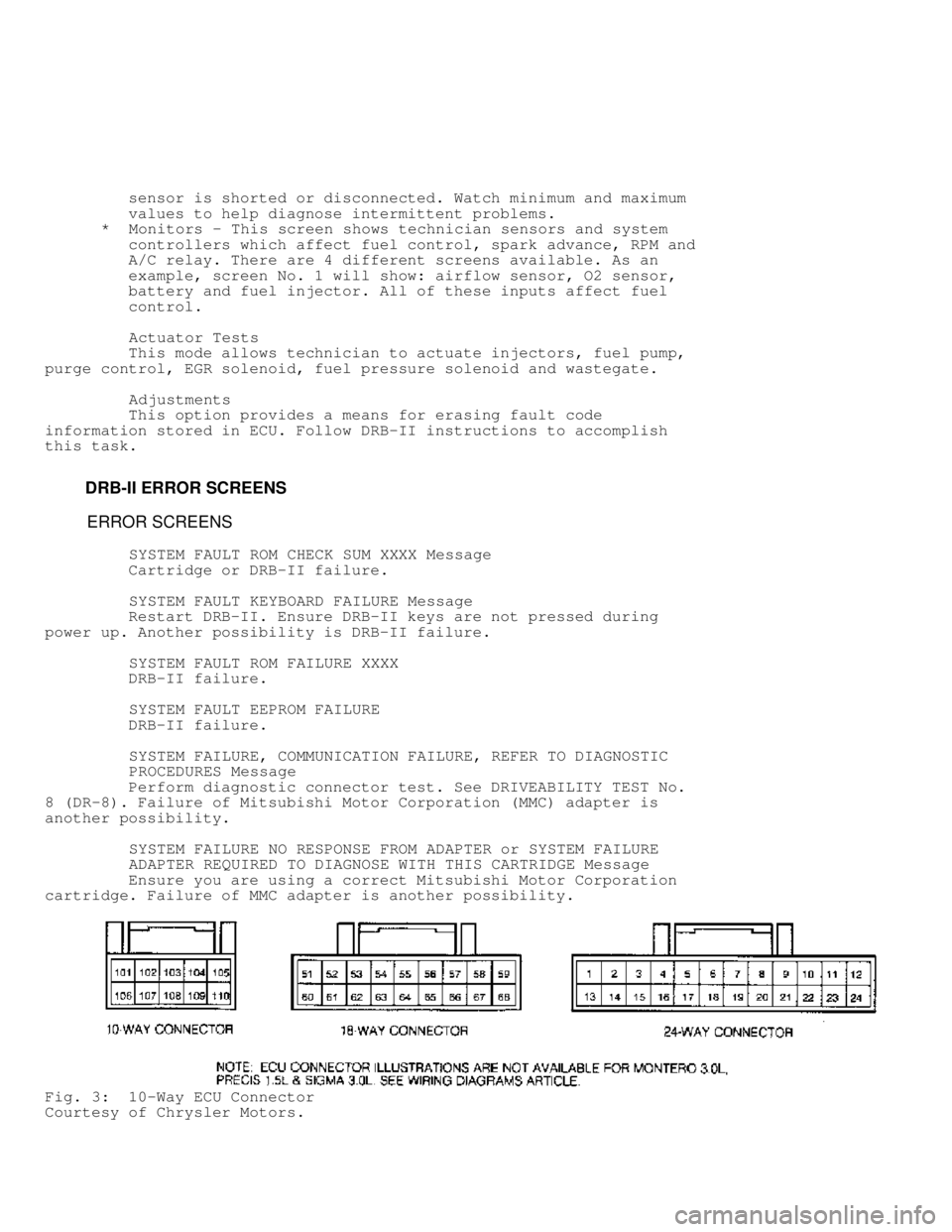
Fig. 3: 10-Way ECU Connector
Courtesy of Chrysler Motors.
Page 889 of 1333
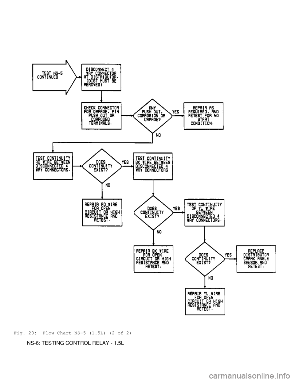
Fig. 20: Flow Chart NS-5 (1.5L) (2 of 2)
NS-6: TESTING CONTROL RELAY - 1.5L
Page 951 of 1333
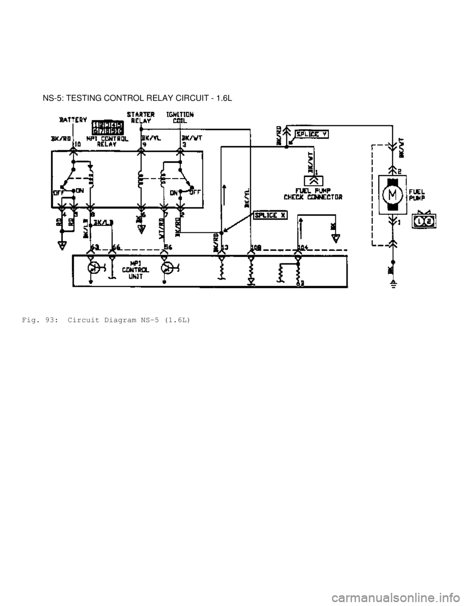
NS-5: TESTING CONTROL RELAY CIRCUIT - 1.6L
Fig. 93: Circuit Diagram NS-5 (1.6L)
Page 1027 of 1333
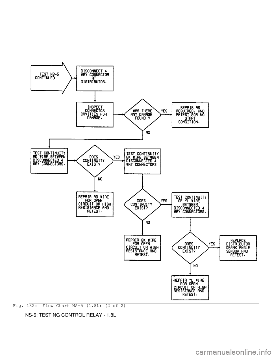
Fig. 182: Flow Chart NS-5 (1.8L) (2 of 2)
NS-6: TESTING CONTROL RELAY - 1.8L
Page 1081 of 1333
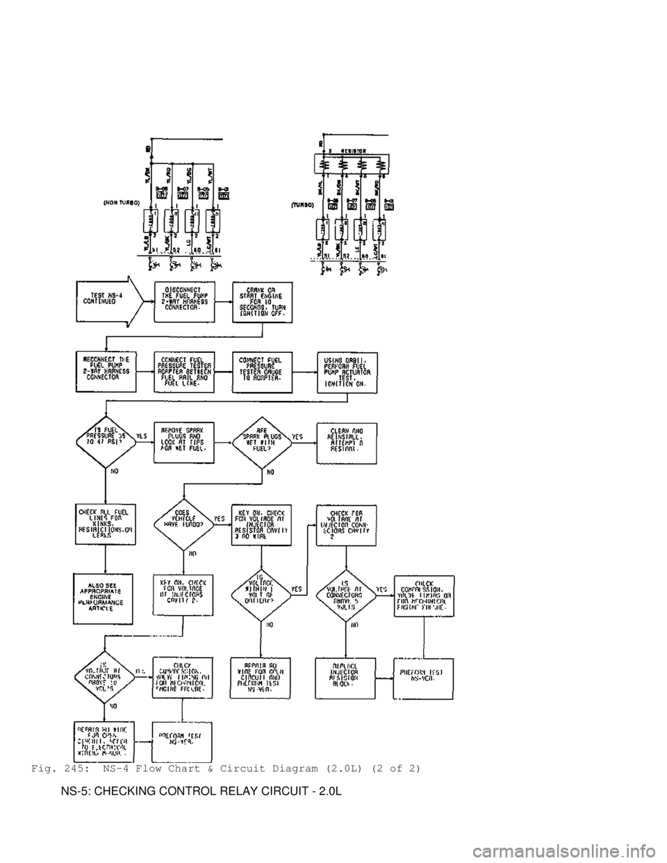
Fig. 245: NS-4 Flow Chart & Circuit Diagram (2.0L) (2 of 2)
NS-5: CHECKING CONTROL RELAY CIRCUIT - 2.0L
Page 1139 of 1333

* Check airflow sensor.
* Check coolant temperature sensor.
* Check idle position switch.
* Check power supply to ECU ground.
* Check fuel pressure.
* Check for disconnected or damaged vacuum hoses.
* Check for control relay malfunction.
* Check for PFI system malfunction.
* Check for fuel pump drive control system malfunction.
* Check for ignition coil malfunction.
* Check for ignition timing malfunction.
* Check for power transistor malfunction.
* Check for fuel injector malfunction.
* Check for ECU malfunction.
* Ensure electrical harness, connectors and wires are not
broken or loose.
ROUGH OR UNSTABLE IDLE
* Check intake air temperature sensor.
* Check purge control solenoid valve (if applicable).
* Check vehicle speed sensor.
* Check engine coolant temperature sensor.
* Check barometric pressure sensor.
* Check ignition switch.
* Check idle position switch.
* Check throttle position sensor.
* Check TDC sensor.
* Check crank angle sensor.
* Check power steering oil pressure switch.
* Check A/C switch and power relay (if applicable).
* Check inhibitor switch.
* Check oxygen sensor.
* Check airflow sensor.
* Check motor position sensor (if equipped).
* Check fuel pressure.
* Check for disconnected or damaged vacuum hoses.
* Check PFI system malfunction.
* Check for stepper motor malfunction (if applicable).
* Check for fuel injector malfunction.
* Check for power transistor malfunction.
* Check for vehicle speed switch malfunction.
* Check for ECU malfunction.
* Ensure electrical harness, connectors and wires are not
broken or loose.
ENGINE HESITATES OR POOR ACCELERATION
* Check intake air temperature sensor.
* Check engine coolant temperature sensor.
* Check barometric pressure sensor.
* Check ignition switch.
* Check ignition coil.
* Check EGR control solenoid valve (if applicable).
* Check idle position switch.
* Check throttle position sensor.
* Check TDC sensor.
* Check crank angle sensor.
* Check power steering oil pressure switch.
* Check A/C switch (if applicable).
* Check inhibitor switch (A/T).
* Check oxygen sensor.
* Check airflow sensor.
Page 1140 of 1333

* Check motor position sensor (if applicable).
* Check fuel pressure.
* Check for disconnected or damaged vacuum hoses.
* Check for PFI system malfunction.
* Check for stepper motor malfunction (if applicable).
* Check for fuel injector malfunction.
* Check for power transistor malfunction.
* Check for A/C power relay control system malfunction (if
applicable).
* Check for ECU malfunction.
* Ensure electrical harness, connectors and wires are not
broken or loose.
ENGINE SURGES
* Check coolant temperature sensor.
* Check idle position switch.
* Check EGR control solenoid valve (if applicable).
* Check fuel pressure.
* Check for fuel injector malfunction.
DETONATION OR KNOCKING
* Check airflow sensor.
* Check for cooling system problems.
* Check fuel quality.
* Check intake air temperature sensor.
* Check barometric pressure sensor.
* Check ignition coil.
* Check power transistor.
* Check for EGR system malfunction.
POOR FUEL MILEAGE
* Check intake air temperature sensor.
* Check engine coolant temperature sensor.
* Check barometric pressure sensor.
* Check ignition switch.
* Check idle position switch.
* Check throttle position sensor.
* Check TDC sensor.
* Check crank angle sensor.
* Check power steering oil pressure switch.
* Check A/C switch (if applicable).
* Check inhibitor switch (A/T).
* Check oxygen sensor.
* Check airflow sensor.
* Check motor position sensor (if applicable).
* Check fuel pressure.
* Check for PFI system malfunction.
* Check for stepper motor malfunction.
* Check for fuel injector malfunction.
* Check for power transistor malfunction.
INTERMITTENTS
INTERMITTENT PROBLEM DIAGNOSIS
Intermittent fault testing requires duplicating circuit or
component failure to identify problem. These procedures may lead to
computer setting a fault code which may help in diagnosis.
If problem vehicle does not produce fault codes, monitor
Page 1144 of 1333

Inhibitor Switch (Automatic Transmission Only)
Inhibitor switch senses position of transmission select
lever, indicating engine load due to automatic transmission
engagement. Based on this signal, ECU commands ISC motor to increase
throttle angle, maintaining optimum idle speed.
Intake Air Temperature Sensor
Incorporated in airflow sensor assembly, this resistor-based
sensor measures temperature of incoming air and supplies air density
information to ECU.
Motor Position Sensor (MPS)
Incorporated in ISC motor (or separate unit on some models),
senses ISC motor plunger position and sends electrical signal to ECU.
Oxygen (O2) Sensor
Located in exhaust system, generates an output voltage.
Output voltage varies with oxygen content of exhaust gas stream. ECU
adjusts air/fuel mixture based on signals from oxygen sensor.
Power Steering Oil Pressure Switch
Detects increase in power steering oil pressure. When power
steering oil pressure increases, switch contacts close, signalling
ECU. ECU commands ISC motor, raising idle speed to compensate for drop
in engine RPM due to power steering load.
TDC Sensor
See CRANKSHAFT ANGLE & TDC SENSOR ASSEMBLY.
Throttle Position Sensor (TPS)
A variable resistor mounted on throttle body. ECU uses
voltage signal received from TPS to determine throttle plate angle.
Vehicle Speed Sensor
Located in speedometer in instrument cluster, uses a reed
switch to sense speedometer gear revolutions. ECU uses gear
revolutions to determine vehicle speed.
OUTPUT SIGNALS
NOTE: Vehicles are equipped with different combinations of
computer-controlled components. Not all components listed
below are used on every vehicle. For theory and operation on
each output component, refer to the system indicated in
brackets after component.
CHECK ENGINE Light
See SELF DIAGNOSTIC SYSTEM.
EGR Control Solenoid Valve
See EXHAUST GAS RECIRCULATION (EGR) CONTROL under EMISSION
SYSTEMS.
Fuel Injectors
See FUEL CONTROL under FUEL SYSTEM.
Fuel Pressure Control Solenoid Valve (Turbo Only)
See FUEL DELIVERY under FUEL SYSTEM.
Fuel Pressure Regulator
See FUEL DELIVERY under FUEL SYSTEM.
Fuel Pump Relay (MPI Control Relay)
Page 1145 of 1333

See FUEL DELIVERY under FUEL SYSTEM.
Idle Speed Control Servo
See IDLE SPEED under FUEL SYSTEM.
Power Transistor(s) & Ignition Coils
See IGNITION SYSTEMS.
Purge Control Solenoid Valve
See EVAPORATIVE CONTROL under EMISSION SYSTEMS.
Self-Diagnostic Connector
See SELF-DIAGNOSTIC SYSTEM.
Wastegate Control Solenoid Valve
See TURBOCHARGED ENGINES under AIR INDUCTION SYSTEM.
FUEL SYSTEM
FUEL DELIVERY
Electric fuel pump (located in gas tank) feeds fuel through
in-tank fuel filter, external fuel filter (located in engine
compartment) and fuel injector rail.
Fuel Pump
Consists of an impeller driven by a motor. Pump has an
internal check valve to maintain system pressure and a relief valve to
protect the fuel pressure circuit. Pump receives voltage supply from
Multi-Point Injection (MPI) control relay.
Fuel Pressure Control Solenoid Valve (Turbo Only)
Prevents rough idle due to fuel percolation. On engine
restart, if engine coolant or intake air temperatures reach a preset
value, ECU applies voltage to fuel pressure control solenoid valve for
2 minutes after engine re-start. Valve opens, allowing atmospheric
pressure to be applied to fuel pressure regulator diaphragm. This
allows maximum available fuel pressure at injectors, enriching fuel
mixture and maintaining stable idle at high engine temperatures.
Fuel Pressure Regulator
Located on fuel injector rail, this diaphragm-operated relief
valve adjusts fuel pressure according to engine manifold vacuum.
As engine manifold vacuum increases (closed throttle), fuel
pressure regulator diaphragm opens relief valve, allowing pressure to
bleed off through fuel return line, reducing fuel pressure.
As engine manifold vacuum decreases (open throttle), fuel
pressure regulator diaphragm closes valve, preventing pressure from
bleeding off through fuel return line, increasing fuel pressure.
FUEL CONTROL
Fuel Injectors
Fuel is supplied to engine through electronically pulsed
(timed) injector valves located on fuel rail(s). ECU controls amount\
of fuel metered through injectors based upon information received from
sensors.
IDLE SPEED
Air Conditioner Relay
When A/C is turned on with engine at idle, ECU signals ISC