lock MITSUBISHI MONTERO 1998 Owners Manual
[x] Cancel search | Manufacturer: MITSUBISHI, Model Year: 1998, Model line: MONTERO, Model: MITSUBISHI MONTERO 1998Pages: 1501, PDF Size: 25.81 MB
Page 307 of 1501
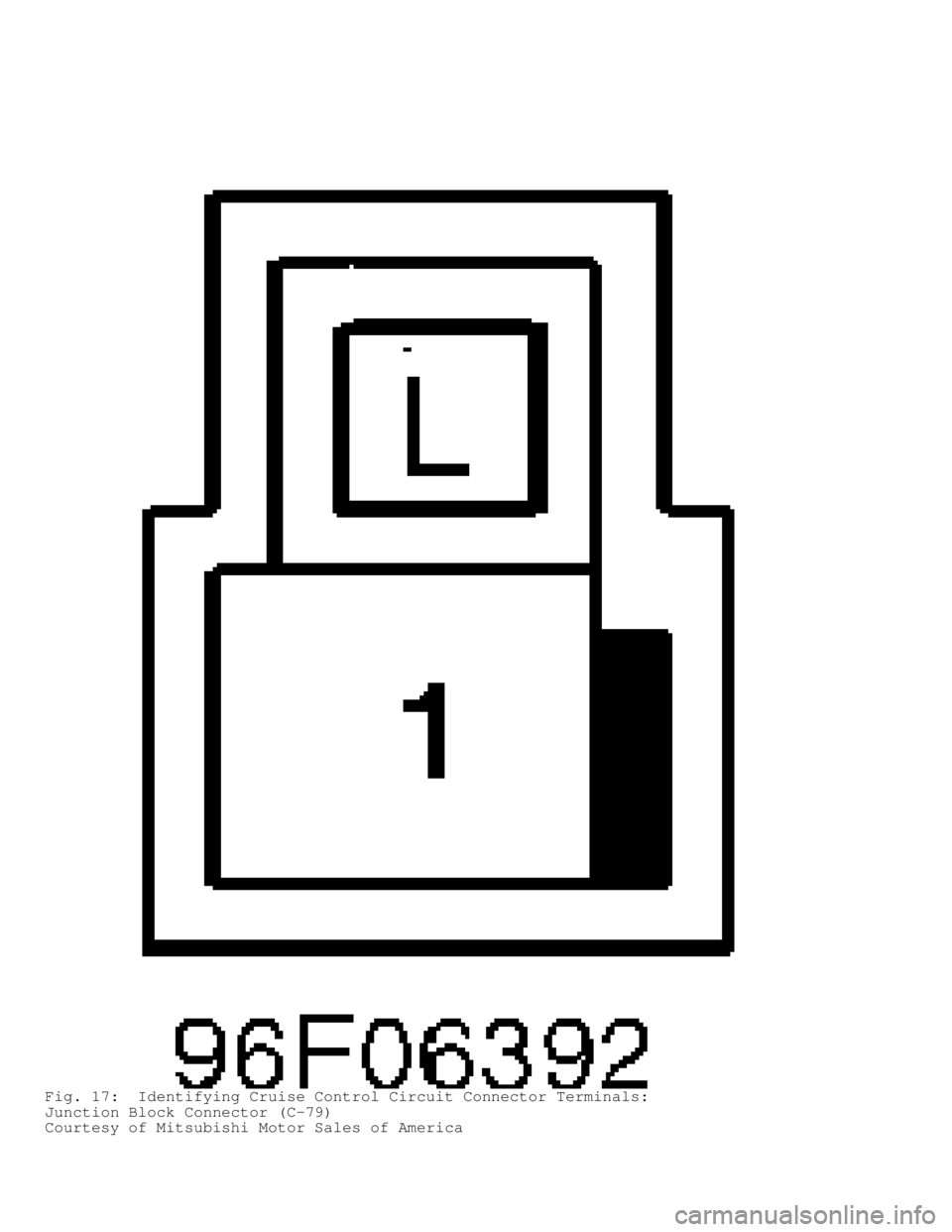
Fig. 17: Identifying Cruise Control Circuit Connector Terminals:
Junction Block Connector (C-79)
Courtesy of Mitsubishi Motor Sales of America
Page 308 of 1501
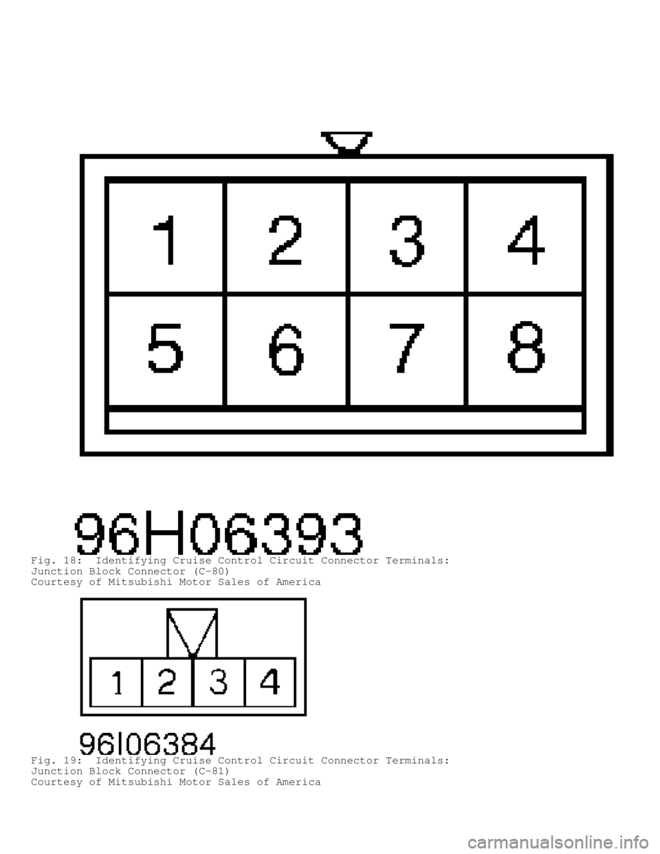
Fig. 18: Identifying Cruise Control Circuit Connector Terminals:
Junction Block Connector (C-80)
Courtesy of Mitsubishi Motor Sales of America
Fig. 19: Identifying Cruise Control Circuit Connector Terminals:
Junction Block Connector (C-81)
Courtesy of Mitsubishi Motor Sales of America
Page 309 of 1501
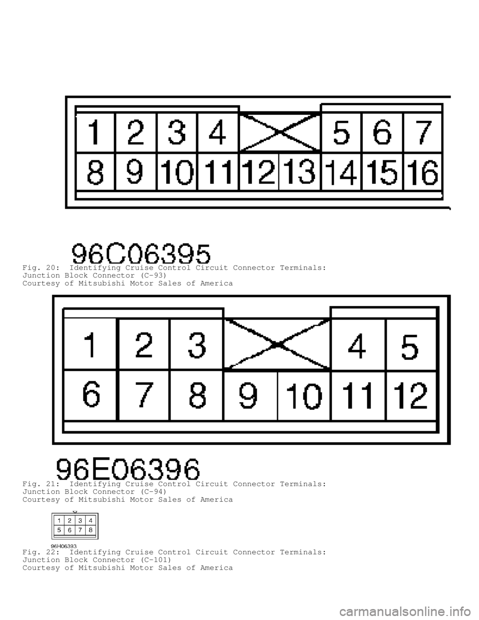
Fig. 20: Identifying Cruise Control Circuit Connector Terminals:
Junction Block Connector (C-93)
Courtesy of Mitsubishi Motor Sales of America
Fig. 21: Identifying Cruise Control Circuit Connector Terminals:
Junction Block Connector (C-94)
Courtesy of Mitsubishi Motor Sales of America
Fig. 22: Identifying Cruise Control Circuit Connector Terminals:
Junction Block Connector (C-101)
Courtesy of Mitsubishi Motor Sales of America
Page 311 of 1501
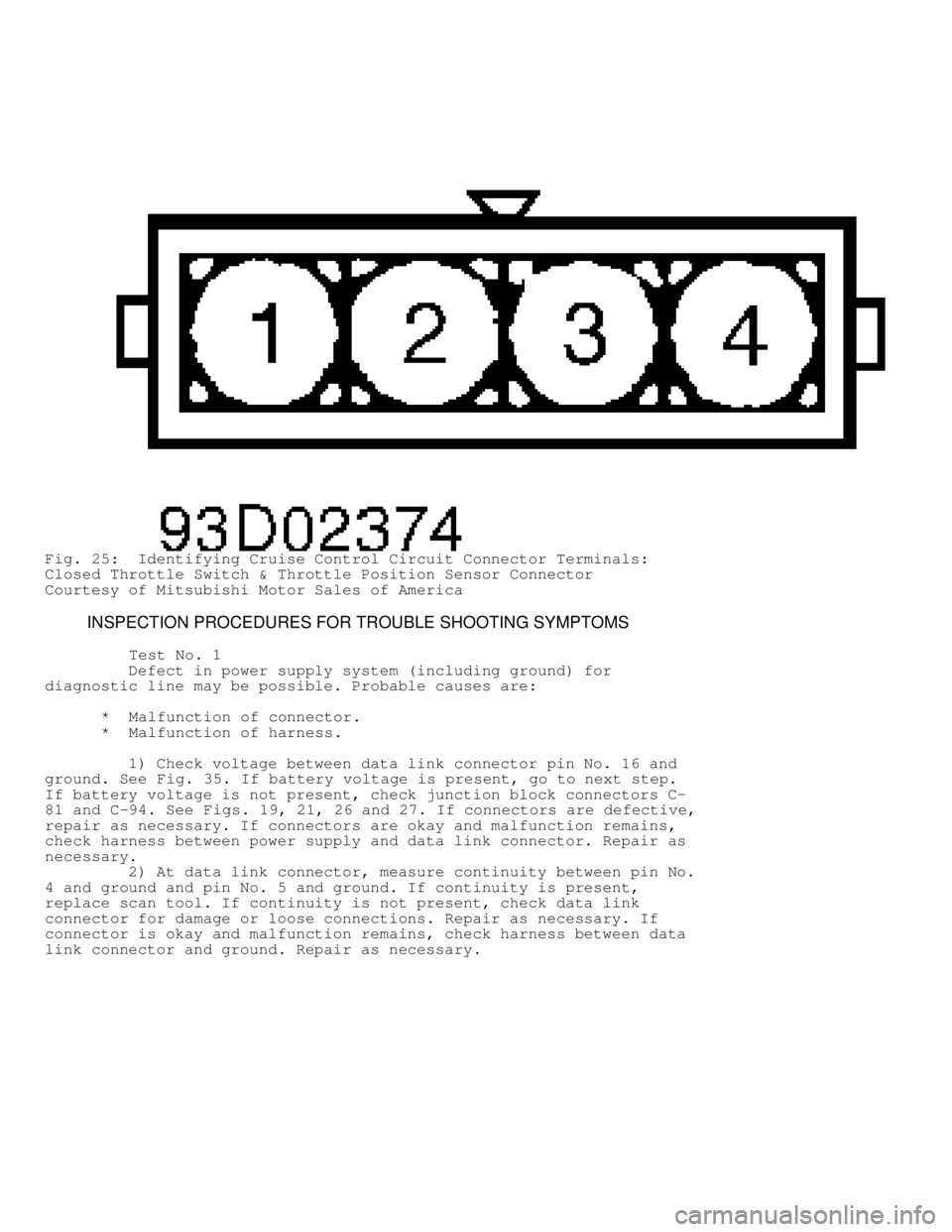
Fig. 25: Identifying Cruise Control Circuit Connector Terminals:
Closed Throttle Switch & Throttle Position Sensor Connector
Courtesy of Mitsubishi Motor Sales of America
INSPECTION PROCEDURES FOR TROUBLE SHOOTING SYMPTOMS
Test No. 1
Defect in power supply system (including ground) for
diagnostic line may be possible. Probable causes are:
* Malfunction of connector.
* Malfunction of harness.
1) Check voltage between data link connector pin No. 16 and
ground. See Fig. 35. If battery voltage is present, go to next step.
If battery voltage is not present, check junction block connectors C-
81 and C-94. See Figs. 19, 21, 26 and 27. If connectors are defective,
repair as necessary. If connectors are okay and malfunction remains,
check harness between power supply and data link connector. Repair as
necessary.
2) At data link connector, measure continuity between pin No.
4 and ground and pin No. 5 and ground. If continuity is present,
replace scan tool. If continuity is not present, check data link
connector for damage or loose connections. Repair as necessary. If
connector is okay and malfunction remains, check harness between data
link connector and ground. Repair as necessary.
Page 312 of 1501
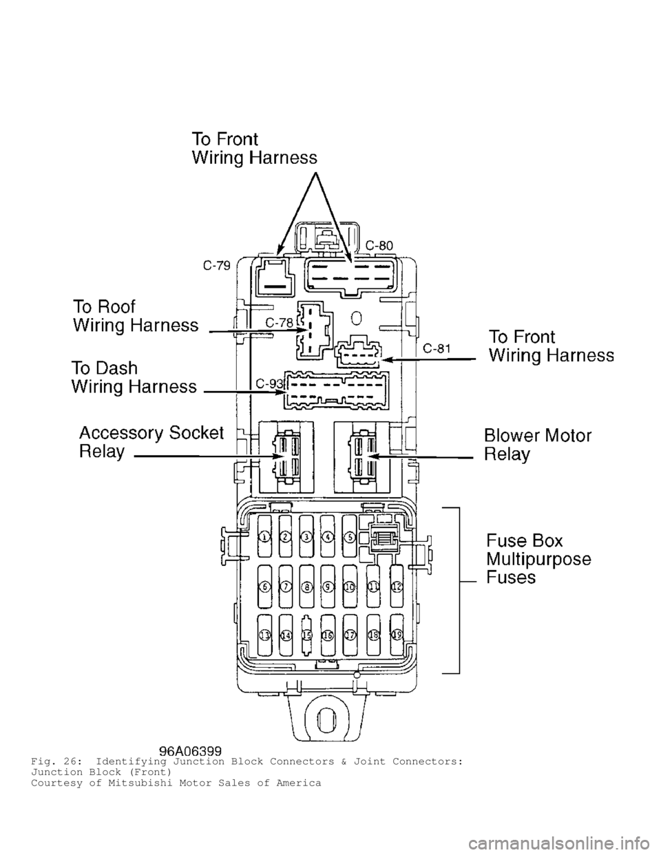
Fig. 26: Identifying Junction Block Connectors & Joint Connectors:
Junction Block (Front)
Courtesy of Mitsubishi Motor Sales of America
Page 313 of 1501
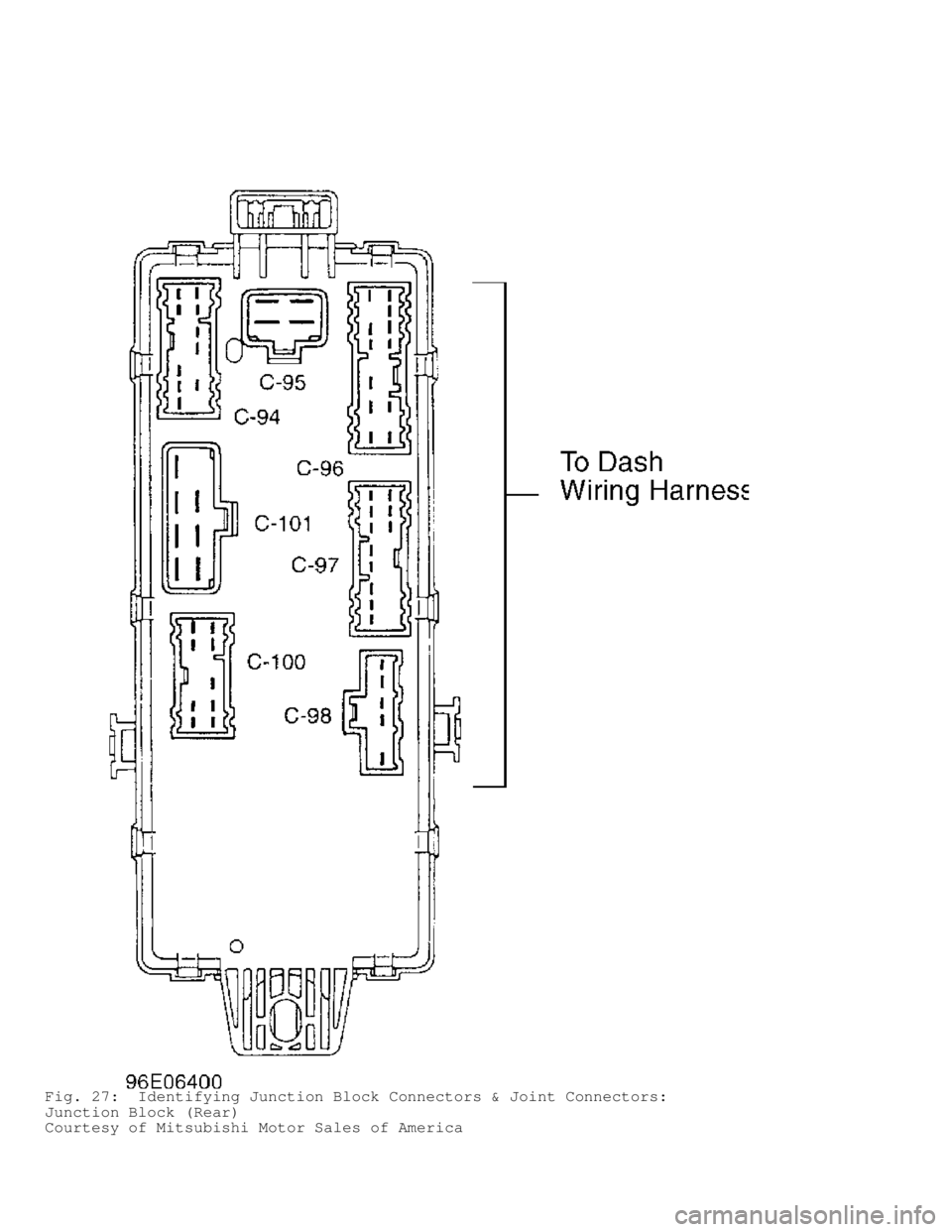
Fig. 27: Identifying Junction Block Connectors & Joint Connectors:
Junction Block (Rear)
Courtesy of Mitsubishi Motor Sales of America
Page 314 of 1501
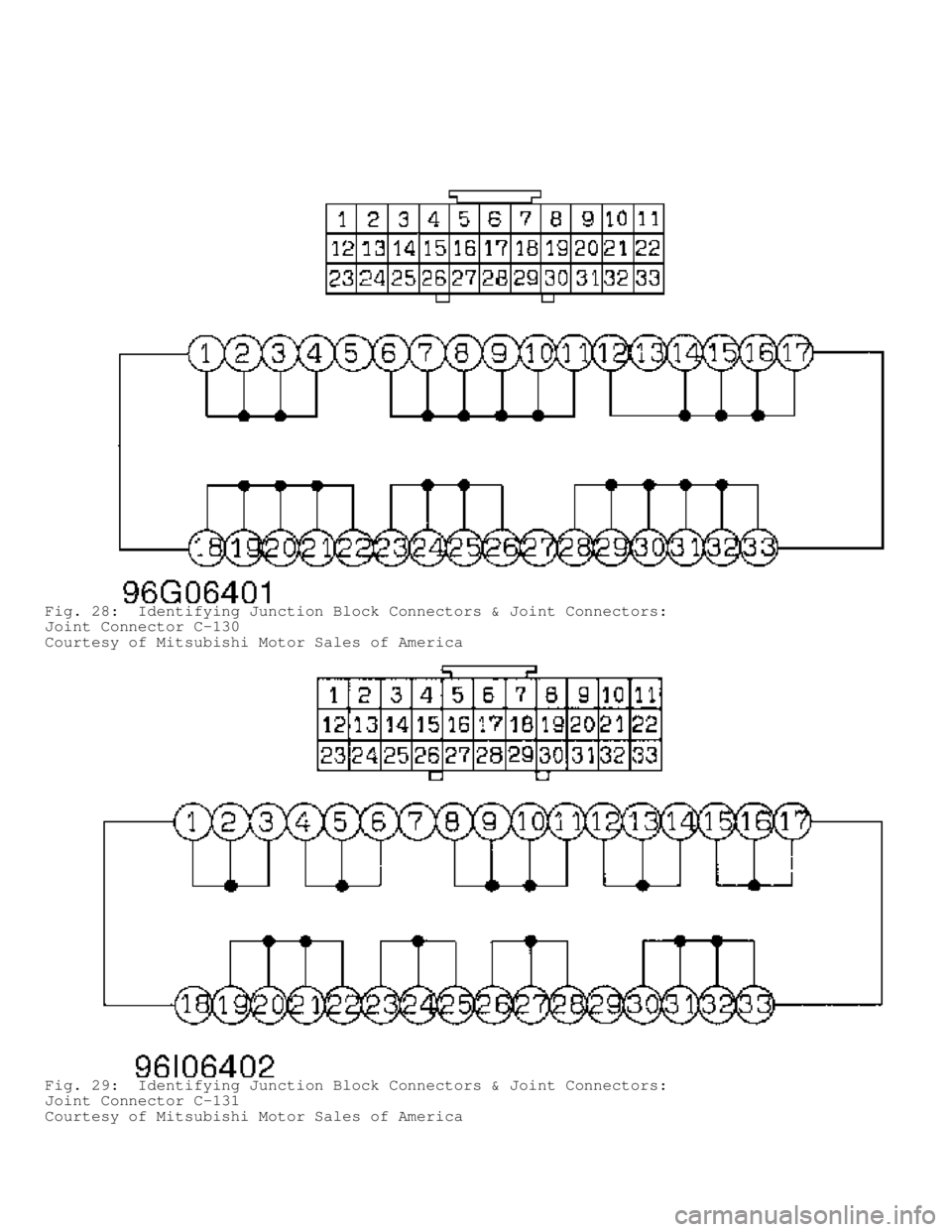
Fig. 28: Identifying Junction Block Connectors & Joint Connectors:
Joint Connector C-130
Courtesy of Mitsubishi Motor Sales of America
Fig. 29: Identifying Junction Block Connectors & Joint Connectors:
Joint Connector C-131
Courtesy of Mitsubishi Motor Sales of America
Page 315 of 1501
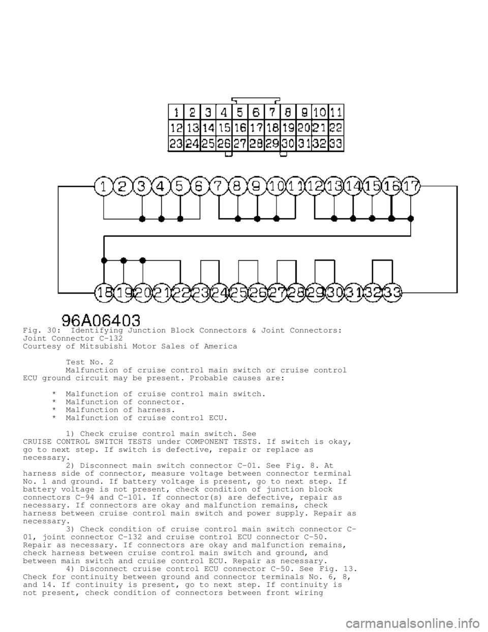
Fig. 30: Identifying Junction Block Connectors & Joint Connectors:
Joint Connector C-132
Courtesy of Mitsubishi Motor Sales of America
Test No. 2
Malfunction of cruise control main switch or cruise control
ECU ground circuit may be present. Probable causes are:
* Malfunction of cruise control main switch.
* Malfunction of connector.
* Malfunction of harness.
* Malfunction of cruise control ECU.
1) Check cruise control main switch. See
CRUISE CONTROL SWITCH TESTS under COMPONENT TESTS. If switch is okay,
go to next step. If switch is defective, repair or replace as
necessary.
2) Disconnect main switch connector C-01. See Fig. 8. At
harness side of connector, measure voltage between connector terminal
No. 1 and ground. If battery voltage is present, go to next step. If
battery voltage is not present, check condition of junction block
connectors C-94 and C-101. If connector(s) are defective, repair as
necessary. If connectors are okay and malfunction remains, check
harness between cruise control main switch and power supply. Repair as
necessary.
3) Check condition of cruise control main switch connector C-
01, joint connector C-132 and cruise control ECU connector C-50.
Repair as necessary. If connectors are okay and malfunction remains,
check harness between cruise control main switch and ground, and
between main switch and cruise control ECU. Repair as necessary.
4) Disconnect cruise control ECU connector C-50. See Fig. 13.
Check for continuity between ground and connector terminals No. 6, 8,
and 14. If continuity is present, go to next step. If continuity is
not present, check condition of connectors between front wiring
Page 316 of 1501

harness, dash wiring harness and joint connector C-132. Repair as
necessary. If malfunction remains, check harness between cruise
control main switch and power supply. Repair as necessary.
5) Check condition of cruise control ECU connector C-50.
Repair as necessary. If connector is okay and malfunction persists,
replace cruise control ECU.
Test No. 3
Malfunction of cruise control main switch or cruise control
ECU ground circuit may be present. Probable causes are:
* Malfunction of cruise control main switch.
* Malfunction of clockspring.
* Malfunction of connector.
* Malfunction of harness.
1) Check cruise control switches. See
CRUISE CONTROL SWITCH TESTS under COMPONENT TESTS. Replace any failed
switch. If switches are okay, check clockspring. See CLOCKSPRING TEST
under COMPONENT TESTS. If clockspring is okay, go to next step.
Replace clockspring if not okay.
2) Disconnect clockspring connector C-128 and measure voltage
between terminal No. 2 and ground. See Fig. 15. If battery voltage is
present, go to next step. If battery voltage is not present, check
condition of IOD connector A-09X, joint connector C-131, junction
block connector C-81, junction block connector C-94 and junction block
connector C-101. Repair as necessary. See Figs. 4, 16, 19, 21, 22, 26,
27 and 29. If connectors are okay and malfunction remains, check
harness between clockspring and power supply. Repair as necessary.
3) Check condition of cruise control ECU connector C-50 and
clockspring connector C-128. Repair as necessary. See Figs. 13 and 15.
If connectors are okay and malfunction remains, check harness between
clockspring and cruise control ECU. Repair as necessary.
Test No. 4
Malfunction of stoplight switch or stoplight circuit may be
present. Probable causes are:
* Malfunction of stoplight switch.
* Malfunction of connector.
* Malfunction of harness.
* Malfunction of cruise control ECU.
1) If stoplight does not illuminate with brake pedal
depressed, go to next step. If stoplight illuminates with pedal
depressed, replace cruise control ECU.
2) Check stoplight switch. See
BRAKELIGHT/STOPLIGHT SWITCH TEST under COMPONENT TESTS. Replace
stoplight switch as necessary. If stoplight switch is okay, go to next
step.
3) Disconnect stoplight switch connector C-55. See Fig. 14.
At harness side of connector, measure voltage between terminal No. 2
and ground. If battery voltage is present, go to next step. If battery
voltage is not present, check condition of joint connector C-131 and
junction block connector C-94. Repair as necessary. See Fig. 26. If
connectors are okay and malfunction remains, check harness between
stoplight switch and power supply. Repair as necessary.
4) Check condition of cruise control ECU connector C-50 and
stoplight switch connector C-55. Repair as necessary. If connectors
are okay and malfunction remains, check harness between stoplight
switch and cruise control ECU. Repair as necessary.
Test No. 5
Page 317 of 1501

An open circuit in output signal circuit in Neutral range is
likely reason for malfunction. Probable causes are:
* Malfunction of park/neutral switch.
* Malfunction of connector.
* Malfunction of harness.
* Malfunction of cruise control ECU.
Check condition of park/neutral switch connector B-08, dash
harness/transmission harness connector C-124, cruise control ECU
connector C-50 and joint connector C-130. Repair as necessary. If
connectors are okay and malfunction remains, check harness between
park/neutral switch and cruise control ECU. Repair as necessary. If
harness is okay, replace cruise control ECU.
Test No. 6
An open circuit in circuit inside CANCEL switch is likely
caused by a malfunction in cruise control switch. Replace cruise
control switch.
Test No. 7
Because of an open circuit in battery back-up circuit system,
fail-safe function prevents diagnostic trouble codes from being
memorized and displayed even though cruise control is canceled.
Probable causes are:
* Malfunction of connector.
* Malfunction of harness.
* Malfunction of cruise control ECU.
1) Disconnect cruise control ECU connector C-50. See Fig. 13.
At harness side of connector, measure voltage between terminal No. 16
and ground. If battery voltage is present, go to next step. If battery
voltage is not present, check and repair IOD connector A-09X, joint
connector C-132, junction block connector C-81 and junction block
connector C-93 as necessary. See Figs. 4, 16, 19, 20, 26 and 30. If
connectors are okay and malfunction remains, check harness between
cruise control ECU and power supply. Repair as necessary.
2) Check condition of cruise control ECU connector C-50.
Repair as necessary. If connector is okay and malfunction remains,
replace cruise control ECU.
Test No. 8
A malfunction of switches or fail-safe function cancelling
cruise control may be present. Probable causes are:
* Malfunction of cruise control main switch.
* Malfunction of cruise control switch.
* Malfunction of clockspring.
* Malfunction of harnesses or connectors.
* Malfunction of park/neutral position switch.
* Malfunction of cruise control ECU.
1) Attach scan tool to DLC. If scan tool can communicate with
cruise control, go to next step. If scan tool cannot communicate with
cruise control, go to TEST NO. 2.
2) If input switch inspection is possible with scan tool, go
to next step. If input switch inspection is not possible, go to TEST
NO. 3.
3) If input switch Code 21, 22 or 27 are still displayed,
replace cruise control main switch. If codes are no longer displayed,
go to next step.
4) If input switch Code 23 is still displayed, go to TEST NO.