oil pressure MITSUBISHI MONTERO 2000 Service Service Manual
[x] Cancel search | Manufacturer: MITSUBISHI, Model Year: 2000, Model line: MONTERO, Model: MITSUBISHI MONTERO 2000Pages: 1839, PDF Size: 29.19 MB
Page 1217 of 1839
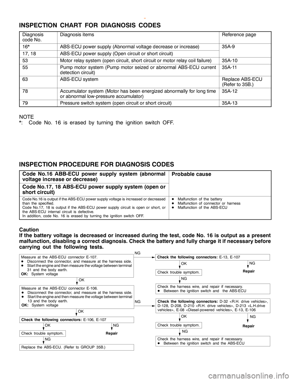
BASIC BRAKE SYSTEM -Troubleshooting35A-9
INSPECTION CHART FOR DIAGNOSIS CODES
Diagnosis
code No.Diagnosis itemsReference page
16*ABS-ECU power supply (Abnormal voltage decrease or increase)35A-9
17, 18ABS-ECU power supply (Open circuit or short circuit)
53Motor relay system (open circuit, short circuit or motor relay coil failure)35A-10
55Pump motor system (Pump motor seized or abnormal ABS-ECU current
detection circuit)35A-11
63ABS-ECU systemReplace ABS-ECU
(Refer to 35B.)
78Accumulator system (Motor has been energized abnormally for long time
or abnormal low-pressure accumulator)35A-12
79Pressure switch system (open circuit or short circuit)35A-13
NOTE
*: Code No. 16 is erased by turning the ignition switch OFF.
INSPECTION PROCEDURE FOR DIAGNOSIS CODES
Code No.16 ABB-ECU power supply system (abnormal
voltage increase or decrease)Probable cause
Code No.17, 18 ABS-ECU power supply system (open or
short circuit)
Code No.16 is output if the ABS-ECU power supply voltage is increased or decreased
than the specified.
Code No.17, 18 is output if the ABS-ECU power supply circuit isopen orshort, or
the ABS-ECU internal circuit is defective.
In addition, code No. 16 is erased by turning the ignition switch OFF.DMalfunction of the battery
DMalfunction of connector or harness
DMalfunction of the ABS-ECU
Caution
If the battery voltage is decreased or increased during the test, code No. 16 is output as a present
malfunction, disabling a correct diagnosis. Check the battery and fully charge it if necessary before
carrying out the following tests.
NG
NG
OK
NG
Replace the ABS-ECU. (Refer to GROUP 35B.)
OK
Check trouble symptom.
NG
Repair
NG
Check the harness wire, and repair if necessary.
DBetween the ignition switch and the ABS-ECU
OK
Check trouble symptom.
Measure at the ABS-ECU connector E-107.
DDisconnect the connector, and measure at the harness side.
DStart theengine and then measure the voltage between terminal
31 and the body earth.
OK:System voltageNGCheck the following connectors:E-13, E-107
Repair
OK
Check the following connectors:E-106, E-107
NG
Check the harness wire, and repair if necessary.
DBetween the ignition switch and the ABS-ECU
OK
Check trouble symptom.
Measure at the ABS-ECU connector E-106.
DDisconnect the connector, and measure at the harness side.
DStart theengine and then measure the voltage between terminal
13 and the body earth.
OK:System voltageNG
Check the following connectors:D-32
D-128, D-208, D-210
Repair
www.WorkshopManuals.co.uk
Purchased from www.WorkshopManuals.co.uk
Page 1265 of 1839

ABS <4WD> -General Information35B-2
GENERAL INFORMATION
ABS has been adopted as standard equipment
in all vehicles to maintain directional stability and
steering performance during sudden braking.
The ABS control method used is a 4-sensor,
4-channel method (previous models: 4-sensor,
3- channel method
)which allows the brake
pressures for all four wheels to be controlled
independently of each other. The system has the
following features.
DEBD
*(Electronic Brake force Distribution
system) control has been added to provide the
ideal braking force for the rear wheels.DThe hydraulic unit function has been integrated
with the hydraulic brake booster (HBB).
DSelect solenoid valves (two valves for FL and
FR) have been adopted in order to reduce the
pedal kickback and improve the operation
feeling when the ABS is operating.
DIndependent 4-wheel control is carried out wile
the vehicle is turning in order to increase the
braking force.
NOTE
*EBD: Electronic Brake-force Distribution
EBD CONTROL
In ABS, electronic control method is used whereby
the rear wheel brake hydraulic pressure during
braking is regulated by rear wheel control solenoid
valves in accordance with the vehicle’s rate of
deceleration and the front and rear wheel slippage
which are calculated from the signals received from
the various wheel sensors. EBD control is a control
system which provides a high level of control for
both vehicle braking force and vehicle stability. The
system has the following features.
DBecause the system provides the optimum rear
wheel braking force regardless of the vehicle
laden condition and the condition of the road
surface, the system reduces the required pedal
depression force, particularly when the vehicle
is heavily laden or driving on road surfaces
with high frictional coefficients.DBecause the duty placed on the front brakes
has been reduced, the increases in pad
temperature can be controlled during front
brakes applying to improve the wear resistance
characteristics of the pad.
DControl valves such as the proportioning valve
are no longer required.
SPECIFICATIONS
ItemSpecifications
ABS control method4-sensor, 4-channel
No. of ABS rotor teethFront50
Rear50
ABS speed sensorTypeMagnet coil type
Gap between sensor and rotor mm0.9 (non-adjustable type)
www.WorkshopManuals.co.uk
Purchased from www.WorkshopManuals.co.uk
Page 1310 of 1839

37A-1
STEERING
CONTENTS
GENERAL INFORMATION 2..................
SERVICE SPECIFICATIONS 5.................
LUBRICANTS 5..............................
SEALANT AND ADHESIVE 5.................
SPECIAL TOOLS 6..........................
ON-VEHICLE SERVICE 8.....................
Steering Wheel Free Play Check 8..............
Steering Angle Check 8........................
Tie Rod End Ball Joint Starting Torque Check 8..
Stationary Steering Effort Check 9...............
Steering Wheel Returnability Check 9............
Oil Pump Belt Tension Check <6G7,4D5> 9......Power Steering Fluid Level Check 10............
Power Steering Fluid Replacement 10...........
Power Steering System Bleeding 10.............
Oil Pump Pressure Test 11.....................
Power Steering Oil Pressure Switch Check
<6G7,4M4> 12.................................
Ball Joint Dust Cover Check 12.................
STEERING WHEEL AND SHAFT* 13.........
POWER STEERING GEAR BOX AND
LINKAGE 16................................
POWER STEERING OIL PUMP 30...........
POWER STEERING OIL HOSES 35..........
WARNINGS REGARDING SERVICING OF SUPPLEMENTAL RESTRAINT SYSTEM (SRS) EQUIPPED VEHICLES
WARNING!
(1) Improper service or maintenance of any component of the SRS, or any SRS-related component, can lead to personal
injury or death to service personnel (from inadvertent firing of the air bag) or to the driver and passenger (from rendering
the SRS inoperative).
(2) Service or maintenance of any SRS component or SRS-related component must be performed only at an authorized
MITSUBISHI dealer.
(3) MITSUBISHI dealer personnel must thoroughly review this manual, and especially its GROUP 52B - Supplemental
Restraint System (SRS) before beginning any service or maintenance of any component of the SRS or any SRS-related
component.
NOTE
The SRS includes the following components: SRS-ECU, SRS warning lamp, air bag module, clock spring and interconnecting
wiring. Other SRS-related components (that mayhave to be removed/installed in connectionwith SRS service or maintenance) are
indicated in the table of contents by an asterisk(*).
www.WorkshopManuals.co.uk
Purchased from www.WorkshopManuals.co.uk
Page 1314 of 1839

STEERING -Service Specifications/Lubricants/Sealant and Adhesive37A-5
SERVICE SPECIFICATIONS
ItemStandard valueLimit
Steering wheel free play mmwith engine running-30 or less
with engine stopped0–10-
Steering angleInner wheel36_30’±1_30’-
Outer wheel31_40’-Outer wheel
Ball joint turning torque N×m0.49 - 2.45-
Stationary steering effort NSteering effort39.2 or less-
Fluctuation allowance5.9 or less-
Oil pump relief pressure MPa8.3 - 9.0-
Pressure under no-load condition MPa<6G7, 4D5>0.34-
<4M4>0.29-
Steering gear retention hydraulic pressure MPa8.3 - 9.0-
Oil pressure switch operating pressureOFF®ON1.5 - 2.0-
MPa <6G7, 4M4>ON®OFF1.5 - 2.0-
Pinion total rotation torque N×mTotal rotation torque0.6 - 1.7-
Torque variation0.4 or less-
Tie rod joint swing resistance N (Tie rod joint swing torque N×m)11 - 35 (1.4 - 4.9)-
Special tool aperture dimension (MB991561) mm2.9-
Band crimped width mm2.4 - 2.8-
LUBRICANTS
ItemSpecified lubricantQuantity
Power steeringAutomatic transmission fluid DEXRONIIAbout 0.6 l
Tie rod bellowsSilicone greaseAs required
Pinion and valve assemblyRepair kit greaseAs required
Rack assemblyRepair kit greaseAs required
SEALANT AND ADHESIVE
ItemSpecified sealantRemarks
Rack support cover end plug3M ATD Part No. 8663 or equivalentSemi-drying sealant
www.WorkshopManuals.co.uk
Purchased from www.WorkshopManuals.co.uk
Page 1763 of 1839

HEATER, AIR CONDITIONER AND VENTILATION - On-vehicle Service55A-17
REFRIGERANT LEAK REPAIR
LOST CHARGE
If the system has lost all charge due to a leak:
1. Evacuate the system. (See procedure.)
2. Charge the system with approximately one
pound of refrigerant.
3. Check for leaks.
4. Discharge the system.
5. Repair leaks.
6. Replace receiver drier.
Caution
Replacement filter-drier units must be
sealed while in storage. The drier used in
these units will saturate water quickly upon
exposure to the atmosphere. When
installing a drier, have all tools and supplies
ready for quick reassembly to avoid keeping
the system open any longer than necessary.
7. Evacuate and charge system.
LOW CHARGE
If the system has not lost all of its refrigerant charge;
locate and repair all leaks. If it is necessary to
increase the system pressure to find the leak
(because of an especially low charge) add
refrigerant. If it is possible to repair the leak without
discharging the refrigerant system, use the
procedure for correcting low refrigerant level.HANDLING TUBING AND FITTINGS
Kinks in the refrigerant tubing or sharp bends in
the refrigerant hose lines will greatly reduce the
capacity of the entire system. High pressures are
produced in the system when it is operating.
Extreme care must be exercised to make sure that
all connections are pressure tight. Dirt and moisture
can enter the system when it is opened for repair
or replacement of lines or components. The
following precautions must be observed. The
system must be completely discharged before
opening any fitting of connection in the refrigeration
system. Open fittings with caution even after the
system has been discharged. If any pressure is
noticed as a fitting is loosened, allow trapped
pressure to bleed off very slowly.
Never attempt to rebend formed lines to fit. Use
the correct line for the installation you are servicing.
A good rule for the flexible hose lines is keep the
radius of all bends at least 10 times the diameter
of the hose.
Sharper bends will reduce the flow of refrigerant.
The flexible hose lines should be routed so that
they are at least 80 mm from the exhaust manifold.
It is good practice to inspect all flexible hose lines
at least once a year to make sure they are in good
condition and properly routed.
Unified plumbing connections with O-rings, these
O-rings are not reusable.
COMPRESSOR NOISE
You must first know the conditions when the noise
occurs. These conditions are: weather, vehicle
speed, in gear or neutral, engine temperature or
any other special conditions.
Noises that develop during A/C operation can often
be misleading. For example: what sounds like a
failed front bearing or connecting rod, may be
caused by loose bolts, nuts, mounting brackets,
or a loose clutch assembly. Verify accessory drive
belt tension (power steering or alternator).
Improper accessory drive belt tension can cause
a misleading noise when the compressor is
engaged and little or no noise when the compressor
is disengaged.
Drive belts are speed-sensitive. That is, at different
engine speeds, and depending upon belt tension,
belts can develop unusual noises that are often
mistaken for mechanical problems within the
compressor.ADJUSTMENT
1. Select a quiet area for testing. Duplicate
conditions as much as possible. Switch
compressor on and off several times to clearly
identify compressor noise. To duplicate high
ambient conditions (high head pressure),
restrict air flow through condenser. Install
manifold gauge set to make sure discharge
pressure doesn’t exceed 2,070 kPa.
2. Tighten all compressor mounting bolts, clutch
mounting bolt, and compressor drive belt.
Check to assure clutch coil is tight (no rotation
or wobble).
3. Check refrigerant hoses for rubbing or
interference that can cause unusual noises.
4. Check refrigerant charge. (See “Charging
System”.)
5. Recheck compressor noise as in Step 1.
6. If noise still exists, loosen compressor mounting
bolts and retorque. Repeat Step 1.
7. If noise continues, replace compressor and
repeat Step 1.
www.WorkshopManuals.co.uk
Purchased from www.WorkshopManuals.co.uk