check oil MITSUBISHI MONTERO 2000 Service Manual PDF
[x] Cancel search | Manufacturer: MITSUBISHI, Model Year: 2000, Model line: MONTERO, Model: MITSUBISHI MONTERO 2000Pages: 1839, PDF Size: 29.19 MB
Page 1218 of 1839
BASIC BRAKE SYSTEM -Troubleshooting35A-10
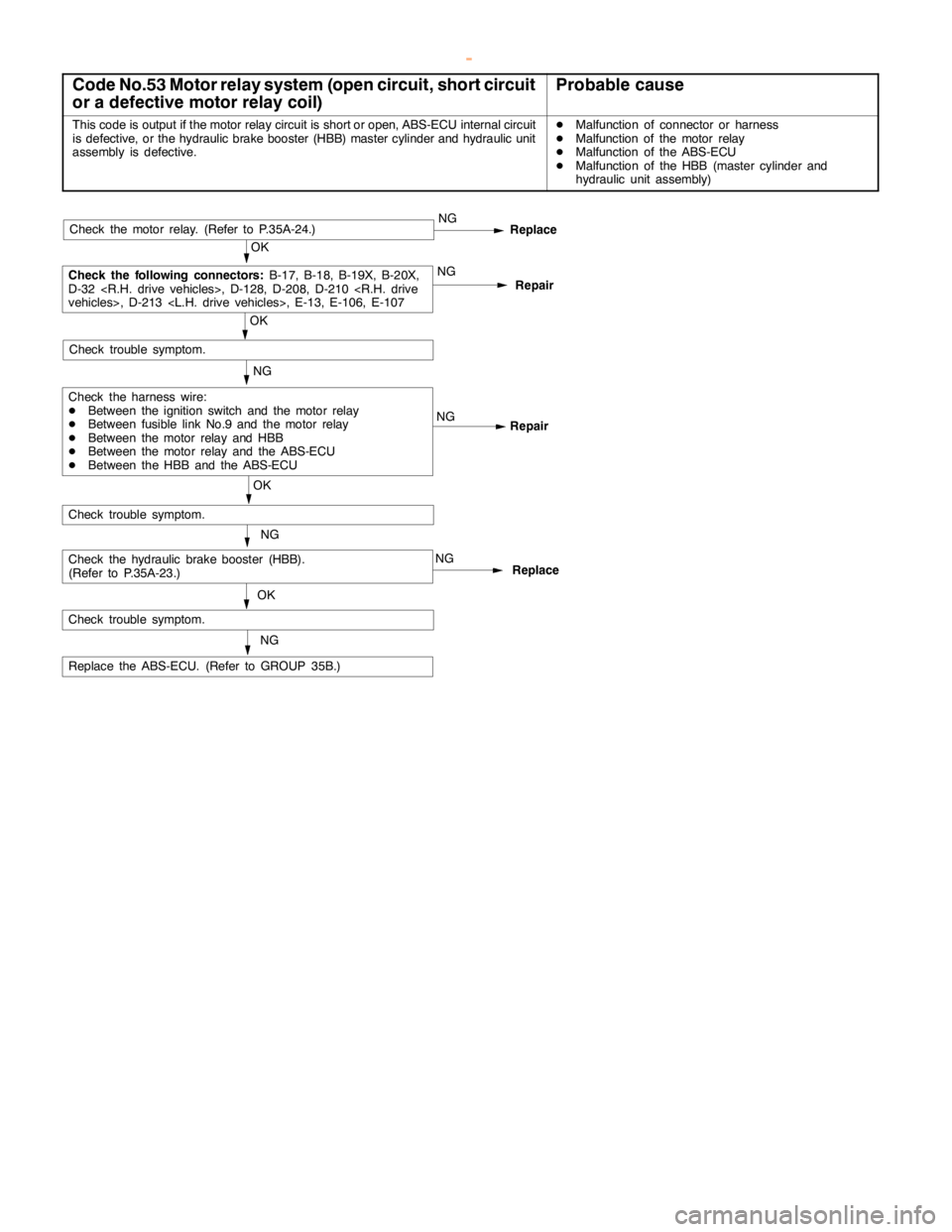
Code No.53 Motor relay system (open circuit, short circuit
or a defective motor relay coil)Probable cause
This code is output if the motor relay circuit is short or open, ABS-ECU internal circuit
is defective, or the hydraulic brake booster (HBB) master cylinder and hydraulic unit
assembly is defective.DMalfunction of connector or harness
DMalfunction of the motor relay
DMalfunction of the ABS-ECU
DMalfunction of the HBB (master cylinder and
hydraulic unit assembly)
NG
Replace the ABS-ECU. (Refer to GROUP 35B.)NG
Repair
NG
OK
Check trouble symptom.
Repair NGNG
OK
Check trouble symptom.
Replace
OK
Check the following connectors:
B-17, B-18, B-19X, B-20X,
D-32
Check the harness wire:
DBetween the ignition switch and the motor relay
DBetween fusible link No.9 and the motor relay
DBetween the motor relay and HBB
DBetween the motor relay and the ABS-ECU
DBetween the HBB and the ABS-ECU
Check trouble symptom.
NG
NG
Replace
OK
Check the motor relay. (Refer to P.35A-24.)
Check the hydraulic brake booster (HBB).
(Refer to P.35A-23.)
www.WorkshopManuals.co.uk
Purchased from www.WorkshopManuals.co.uk
Page 1278 of 1839
ABS <4WD> -Troubleshooting35B-15
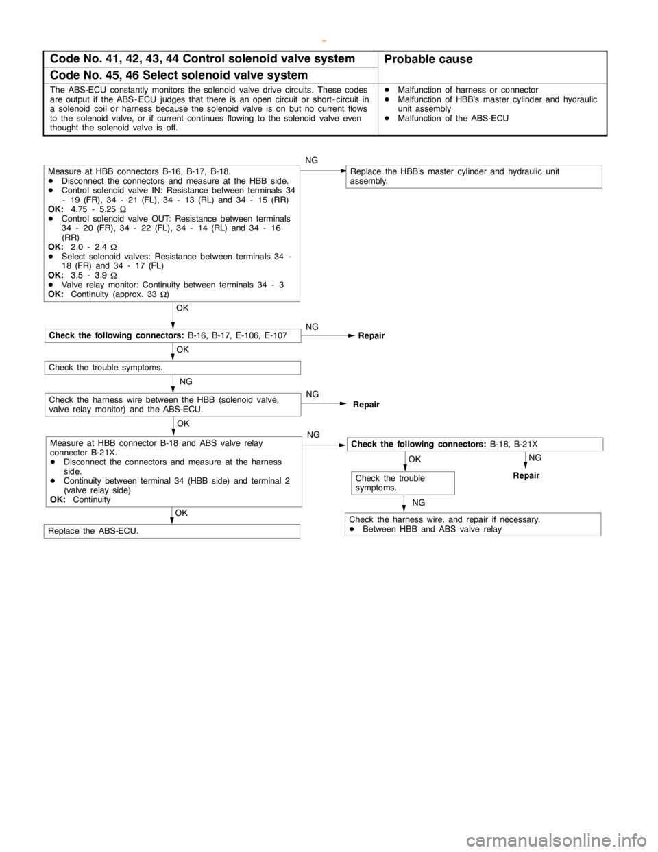
Code No. 41, 42, 43, 44 Control solenoid valve systemProbable cause
Code No. 45, 46 Select solenoid valve system
The ABS-ECU constantly monitors the solenoid valve drive circuits. These codes
are output if the ABS - ECU judges that there is an opencircuit or short - circuit in
a solenoid coil or harness because the solenoid valve is on but no current flows
to the solenoid valve, or if current continues flowing to the solenoid valve even
thought the solenoid valve is off.DMalfunction of harness or connector
DMalfunction of HBB’s master cylinder and hydraulic
unit assembly
DMalfunction of the ABS-ECU
NG
NG
OK
Repair
NG
Replace the HBB’s master cylinder and hydraulic unit
assembly.
OK
Check the following connectors:B-18, B-21X
Check the harness wire, and repair if necessary.
DBetween HBB and ABS valve relay
OK
Check the trouble
symptoms.
NG
Repair
OK
OK
Replace the ABS-ECU.
Repair
Measure at HBB connectors B-16, B-17, B-18.
DDisconnect the connectors and measure at the HBB side.
DControl solenoid valve IN: Resistance between terminals 34
- 19 (FR), 34 - 21 (FL), 34 - 13 (RL) and 34 - 15 (RR)
OK:4.75 - 5.25
W
DControl solenoid valve OUT: Resistance between terminals
34 - 20 (FR), 34 - 22 (FL), 34 - 14 (RL) and 34 - 16
(RR)
OK:2.0 - 2.4
W
DSelect solenoid valves: Resistance between terminals 34 -
18 (FR) and 34 - 17 (FL)
OK:3.5 - 3.9
W
DValve relay monitor: Continuity between terminals 34 - 3
OK:Continuity (approx. 33
W)
NG
Check the following connectors:B-16, B-17, E-106, E-107
Check the trouble symptoms.
NG
Check the harness wire between the HBB (solenoid valve,
valve relay monitor) and the ABS-ECU.
Measure at HBB connector B-18 and ABS valve relay
connector B-21X.
DDisconnect the connectors and measure at the harness
side.
DContinuity between terminal 34 (HBB side) and terminal 2
(valve relay side)
OK:ContinuityNG
www.WorkshopManuals.co.uk
Purchased from www.WorkshopManuals.co.uk
Page 1310 of 1839

37A-1
STEERING
CONTENTS
GENERAL INFORMATION 2..................
SERVICE SPECIFICATIONS 5.................
LUBRICANTS 5..............................
SEALANT AND ADHESIVE 5.................
SPECIAL TOOLS 6..........................
ON-VEHICLE SERVICE 8.....................
Steering Wheel Free Play Check 8..............
Steering Angle Check 8........................
Tie Rod End Ball Joint Starting Torque Check 8..
Stationary Steering Effort Check 9...............
Steering Wheel Returnability Check 9............
Oil Pump Belt Tension Check <6G7,4D5> 9......Power Steering Fluid Level Check 10............
Power Steering Fluid Replacement 10...........
Power Steering System Bleeding 10.............
Oil Pump Pressure Test 11.....................
Power Steering Oil Pressure Switch Check
<6G7,4M4> 12.................................
Ball Joint Dust Cover Check 12.................
STEERING WHEEL AND SHAFT* 13.........
POWER STEERING GEAR BOX AND
LINKAGE 16................................
POWER STEERING OIL PUMP 30...........
POWER STEERING OIL HOSES 35..........
WARNINGS REGARDING SERVICING OF SUPPLEMENTAL RESTRAINT SYSTEM (SRS) EQUIPPED VEHICLES
WARNING!
(1) Improper service or maintenance of any component of the SRS, or any SRS-related component, can lead to personal
injury or death to service personnel (from inadvertent firing of the air bag) or to the driver and passenger (from rendering
the SRS inoperative).
(2) Service or maintenance of any SRS component or SRS-related component must be performed only at an authorized
MITSUBISHI dealer.
(3) MITSUBISHI dealer personnel must thoroughly review this manual, and especially its GROUP 52B - Supplemental
Restraint System (SRS) before beginning any service or maintenance of any component of the SRS or any SRS-related
component.
NOTE
The SRS includes the following components: SRS-ECU, SRS warning lamp, air bag module, clock spring and interconnecting
wiring. Other SRS-related components (that mayhave to be removed/installed in connectionwith SRS service or maintenance) are
indicated in the table of contents by an asterisk(*).
www.WorkshopManuals.co.uk
Purchased from www.WorkshopManuals.co.uk
Page 1596 of 1839
CHASSIS ELECTRICAL-Combination Meter54A-26
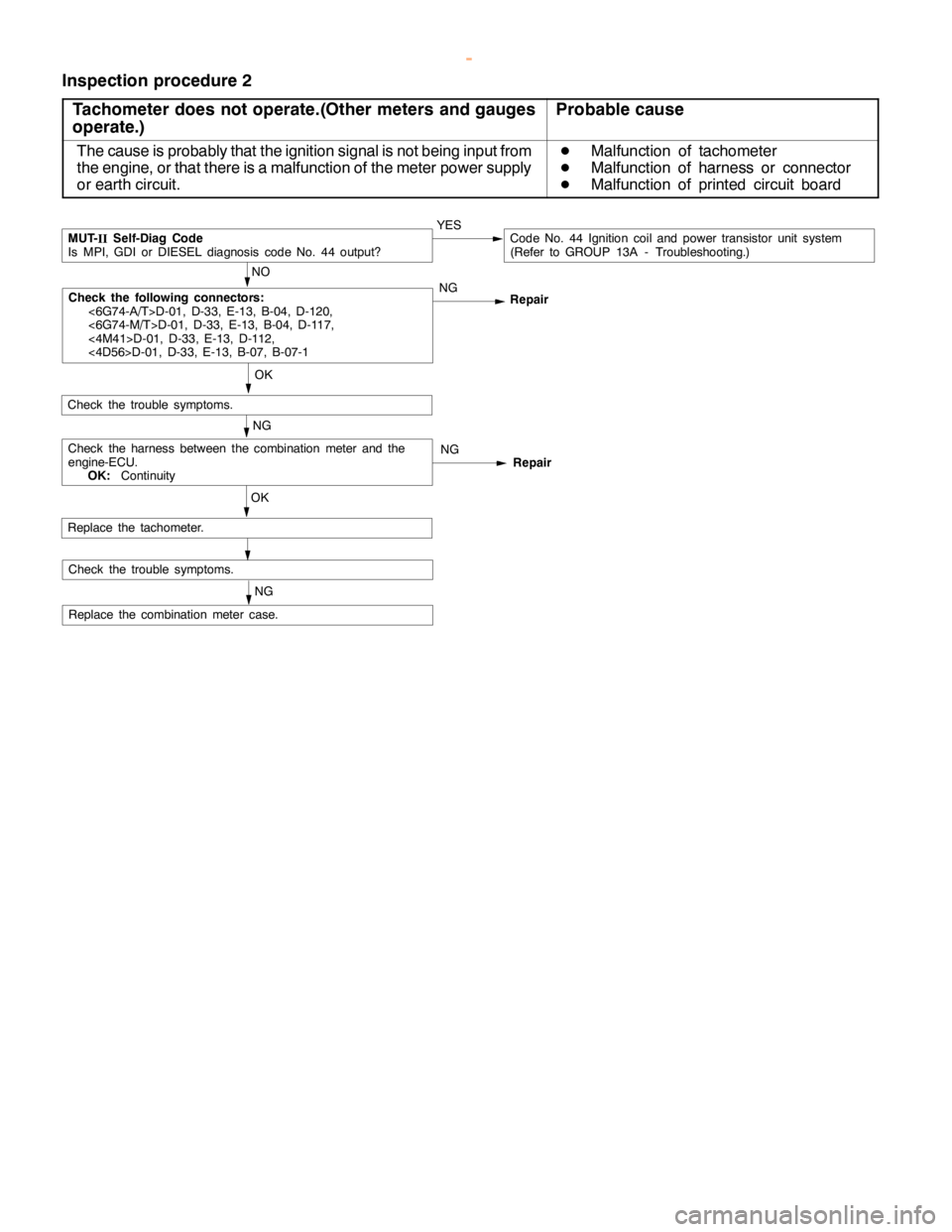
Inspection procedure 2
Tachometer does not operate.(Other meters and gauges
operate.)
Probable cause
The cause is probably that the ignition signal is not being input from
the engine, or that there is a malfunction of the meter power supply
or earth circuit.D
Malfunction of tachometer
D
Malfunction of harness or connector
D
Malfunction of printed circuit board
OK
NG
Replace the combination meter case.
OK
Check the trouble symptoms.
NO
MUT-
IISelf-Diag Code
Is MPI, GDI or DIESEL diagnosis code No. 44 output?YESCode No. 44 Ignition coil and power transistor unit system
(Refer to GROUP 13A - Troubleshooting.)
NG
Replace the tachometer.
NG
NG
Repair RepairCheck the harness between the combination meter and the
engine-ECU.
OK:Continuity
Check the trouble symptoms.
Check the following connectors:
<6G74-A/T>D-01, D-33, E-13, B-04, D-120,
<6G74-M/T>D-01, D-33, E-13, B-04, D-117,
<4M41>D-01, D-33, E-13, D-112,
<4D56>D-01, D-33, E-13, B-07, B-07-1
www.WorkshopManuals.co.uk
Purchased from www.WorkshopManuals.co.uk
Page 1763 of 1839

HEATER, AIR CONDITIONER AND VENTILATION - On-vehicle Service55A-17
REFRIGERANT LEAK REPAIR
LOST CHARGE
If the system has lost all charge due to a leak:
1. Evacuate the system. (See procedure.)
2. Charge the system with approximately one
pound of refrigerant.
3. Check for leaks.
4. Discharge the system.
5. Repair leaks.
6. Replace receiver drier.
Caution
Replacement filter-drier units must be
sealed while in storage. The drier used in
these units will saturate water quickly upon
exposure to the atmosphere. When
installing a drier, have all tools and supplies
ready for quick reassembly to avoid keeping
the system open any longer than necessary.
7. Evacuate and charge system.
LOW CHARGE
If the system has not lost all of its refrigerant charge;
locate and repair all leaks. If it is necessary to
increase the system pressure to find the leak
(because of an especially low charge) add
refrigerant. If it is possible to repair the leak without
discharging the refrigerant system, use the
procedure for correcting low refrigerant level.HANDLING TUBING AND FITTINGS
Kinks in the refrigerant tubing or sharp bends in
the refrigerant hose lines will greatly reduce the
capacity of the entire system. High pressures are
produced in the system when it is operating.
Extreme care must be exercised to make sure that
all connections are pressure tight. Dirt and moisture
can enter the system when it is opened for repair
or replacement of lines or components. The
following precautions must be observed. The
system must be completely discharged before
opening any fitting of connection in the refrigeration
system. Open fittings with caution even after the
system has been discharged. If any pressure is
noticed as a fitting is loosened, allow trapped
pressure to bleed off very slowly.
Never attempt to rebend formed lines to fit. Use
the correct line for the installation you are servicing.
A good rule for the flexible hose lines is keep the
radius of all bends at least 10 times the diameter
of the hose.
Sharper bends will reduce the flow of refrigerant.
The flexible hose lines should be routed so that
they are at least 80 mm from the exhaust manifold.
It is good practice to inspect all flexible hose lines
at least once a year to make sure they are in good
condition and properly routed.
Unified plumbing connections with O-rings, these
O-rings are not reusable.
COMPRESSOR NOISE
You must first know the conditions when the noise
occurs. These conditions are: weather, vehicle
speed, in gear or neutral, engine temperature or
any other special conditions.
Noises that develop during A/C operation can often
be misleading. For example: what sounds like a
failed front bearing or connecting rod, may be
caused by loose bolts, nuts, mounting brackets,
or a loose clutch assembly. Verify accessory drive
belt tension (power steering or alternator).
Improper accessory drive belt tension can cause
a misleading noise when the compressor is
engaged and little or no noise when the compressor
is disengaged.
Drive belts are speed-sensitive. That is, at different
engine speeds, and depending upon belt tension,
belts can develop unusual noises that are often
mistaken for mechanical problems within the
compressor.ADJUSTMENT
1. Select a quiet area for testing. Duplicate
conditions as much as possible. Switch
compressor on and off several times to clearly
identify compressor noise. To duplicate high
ambient conditions (high head pressure),
restrict air flow through condenser. Install
manifold gauge set to make sure discharge
pressure doesn’t exceed 2,070 kPa.
2. Tighten all compressor mounting bolts, clutch
mounting bolt, and compressor drive belt.
Check to assure clutch coil is tight (no rotation
or wobble).
3. Check refrigerant hoses for rubbing or
interference that can cause unusual noises.
4. Check refrigerant charge. (See “Charging
System”.)
5. Recheck compressor noise as in Step 1.
6. If noise still exists, loosen compressor mounting
bolts and retorque. Repeat Step 1.
7. If noise continues, replace compressor and
repeat Step 1.
www.WorkshopManuals.co.uk
Purchased from www.WorkshopManuals.co.uk