check oil MITSUBISHI MONTERO 2000 Service Service Manual
[x] Cancel search | Manufacturer: MITSUBISHI, Model Year: 2000, Model line: MONTERO, Model: MITSUBISHI MONTERO 2000Pages: 1839, PDF Size: 29.19 MB
Page 745 of 1839

INTAKE AND EXHAUST -Turbocharger and Exhaust
Manifold <4M4>15-13
INSTALLATION SERVICE POINT
"AATURBOCHARGER ASSEMBLY INSTALLATION
1. Check the internal surface, the eye bolt and the
mating surface of the oil pipe and water pipe for
clogging, and clean if necessary.
2. If deposits of carbon are accumulated on the
turbocharger oil passage, remove them and clean
using the compressed air.
Caution
Be careful not to allow foreign material to enter the
turbocharger.
3. Add clean engine oil through the oil feed pipe port
on the turbocharger.
www.WorkshopManuals.co.uk
Purchased from www.WorkshopManuals.co.uk
Page 749 of 1839

16-1
ENGINE
ELECTRICAL
CONTENTS
CHARGING SYSTEM 2................
GENERAL INFORMATION 2................
SERVICE SPECIFICATIONS 3..............
SPECIAL TOOL 4.........................
ON-VEHICLE SERVICE 5..................
Alternator Output Line Voltage Drop Test 5....
Output Current Test 6.......................
Regulated Voltage Test 8....................
Waveform Check Using An Analyzer 11.......
ALTERNATOR 13.........................
STARTING SYSTEM 23................
GENERAL INFORMATION 23..............
SERVICE SPECIFICATIONS 24............
STARTER MOTOR 24.....................
IGNITION SYSTEM 37.................
GENERAL INFORMATION 37..............
SERVICE SPECIFICATIONS 38............
SPECIAL TOOL 38.......................
ON-VEHICLE SERVICE 38................
Ignition Coil (With Built-in Power Transistor)
Check 38...................................
Spark Plug Check and Cleaning 39...........
Ignition Failure Sensor Check 40.............
Camshaft Position Sensor Check, Crank angle
Sensor Check, Detonation Sensor Check 40...
IGNITION COIL <6G7> 41.................
CRANKSHAFT ANGLE SENSOR
<6G7> 42................................
CAMSHAFT POSITION SENSOR
<6G7> 42................................
DETONATION SENSOR <6G7> 43.........
GLOW SYSTEM 44....................
GENERAL INFORMATION 44..............
SERVICE SPECIFICATIONS 45............
ON-VEHICLE SERVICE 45................
Self-regulating Glow System Check 45........
Glow & EGR Control Unit Check 48..........
Engine ECU Check 49.......................
Glow Plug Relay Check 50..................
Glow Plug Check 51........................
Engine Coolant Temperature Sensor
Check 51...................................
GLOW PLUG 52..........................
www.WorkshopManuals.co.uk
Purchased from www.WorkshopManuals.co.uk
Page 787 of 1839

ENGINE ELECTRICAL -Ignition System16-39
Voltage: 1.5VTerminal No.
123
When current is
flowing
When current is
not flowing
SECONDARY COIL CHECK
NOTE
It is impossible to check the secondary coil through the
continuity check as a diode is integrated in the secondary
coil circuit of this ignition coil. So, check the secondary coil
in the following procedure.
1. Disconnect the ignition coil connector.
2. Remove the ignition coil and install a new spark plug
to the ignition coil.
3. Connect the ignition coil connector.
4. Earth the side electrode of the spark plug and crank
the engine.
5. Check that spark is produced between the electrodes of
the spark plug.
6. If no spark is produced, replace the ignition coil with a
new one and recheck.
7. If spark is produced with the new ignition coil, replace
the old one as it is faulty. If no spark is produced again,
the ignition circuit is suspected as faulty. Check the ignition
circuit.
SPARK PLUG CHECK AND CLEANING
Caution
1. The spark plug gap for iridium plugs should not be
adjusted.
2. Cleaning iridium plugs may result in damage to the
iridium tip. Therefore, if cleaning is necessary
because the plug is sooty, use a plug cleaner, and
do not clean the plug for more than 20 seconds in
order to preserve the electrodes. A wire brush should
never be used.
3. The spark plugs in GDI engines are special iridium
plugs in which the electrodes can become black even
when the plugs are working normally. Carbon which
may become deposited on these plugs burns off more
readily than with conventional plugs, and so should
not cause any problems with spark plug performance.
Judgement of whether a spark plug is operating
normally or not should be made by checking the
insulation resistance.
www.WorkshopManuals.co.uk
Purchased from www.WorkshopManuals.co.uk
Page 881 of 1839

22-1
MANUAL
TRANSMISSION
CONTENTS
GENERAL INFORMATION 2..................
LUBRICANTS 2..............................
SEALANTS 2................................
SPECIAL TOOL 2............................
TROUBLESHOOTING
ON-VEHICLE SERVICE 6.....................
Transmission Oil Check 6.......................
Oil Replacement 6.............................4WD Detection Switch Continuity Check
High/Low Detection Switch Continuity Check
TRANSMISSION CONTROL
TRANSMISSION CONTROL
TRANSMISSION ASSEMBLY 10..............
4WD INDICATOR-ECU/TRANSFER-ECU 17....
www.WorkshopManuals.co.uk
Purchased from www.WorkshopManuals.co.uk
Page 886 of 1839
O
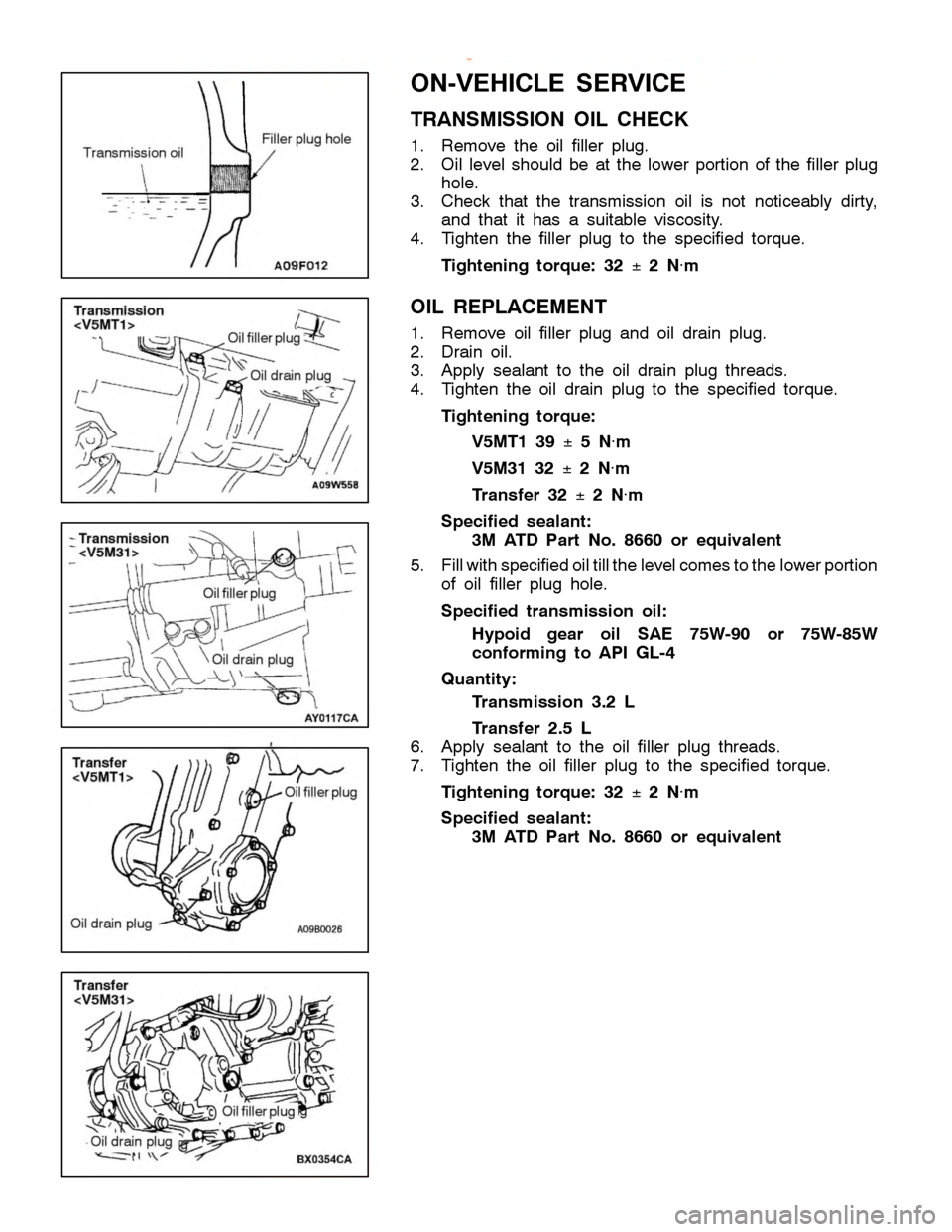
N-V EH IC LE SER VIC E
T R ANSM IS SIO N OIL CHEC K
1 . Rem ove th e oil fille r plu g.
2 . Oil le ve l sh ould be at th e lo w er portio n of th e fille r plu g
h ole .
3 . Check th at th e tr a nsm is sio n oil is not notic e ably dir ty ,
a nd th at it has a su it a ble vis co sit y .
4 . Tig hte n th e fille r plu g to th e sp ecif ie d to rq ue.
T ig hte n in g to rq ue: 32 ±
2 N×
m
O IL REPLA CEM EN T
1 . Rem ove oil fille r plu g and oil dra in plu g.
2 . Dra in oil.
3 . Apply se ala nt to th e oil dra in plu g th re ads.
4 . Tig hte n th e oil dra in plu g to th e sp ecif ie d to rq ue.
T ig hte n in g to rq ue:
V 5M T1 39 ±
5 N×
m
V 5M 31 32 ±
2 N×
m
T ra n sfe r 32 ±
2 N×
m
S pecif ie d seala n t:
3 M ATD Part No. 8660 or eq uiv ale n t
5 . Fill w it h sp ecif ie d oil till th e le ve lc o m es to th e lo w erp ortio n
o f oil fille r plu g hole .
S pecif ie d tr a n sm is sio n oil:
H yp oid gear oil SA E 75W -9 0 or 75W -8 5W
c o nfo rm in g to API G L-4
Q uan tit y :
T ra n sm is sio n 3.2 L
T ra n sfe r 2.5 L
6 . Apply se ala nt to th e oil fille r plu g th re ads.
7 . Tig hte n th e oil fille r plu g to th e sp ecif ie d to rq ue.
T ig hte n in g to rq ue: 32 ±
2 N×
m
S pecif ie d seala n t:
3 M ATD Part No. 8660 or eq uiv ale n t F
ille r plu g hole O
il d ra in plu g O
il fille rp lu g O
il d ra in plu g T
ra n sfe r
< V 5M T1> O
il fille rp lu g O
il d ra in plu g O
il fille rp lu g O
il fille rp lu g O
il d ra in plu g
Page 902 of 1839

Page 950 of 1839
Page 951 of 1839
Page 952 of 1839
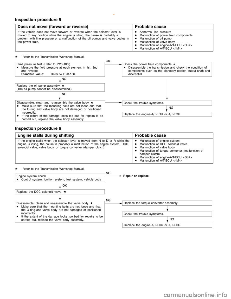
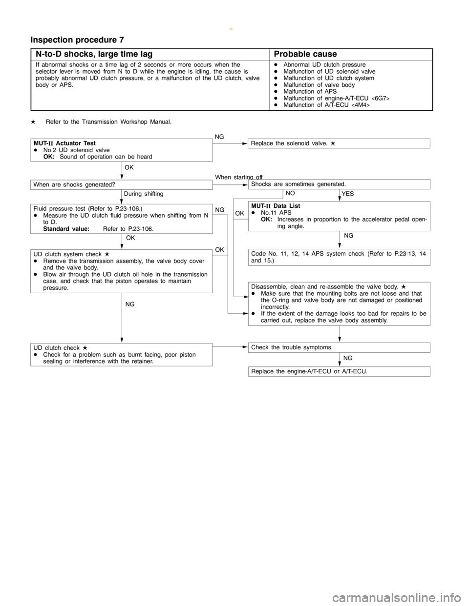
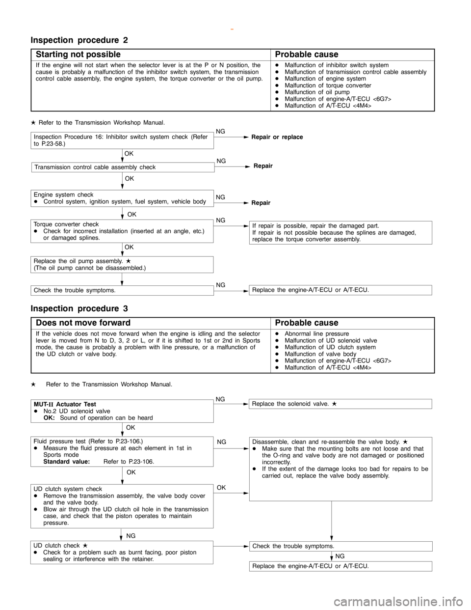
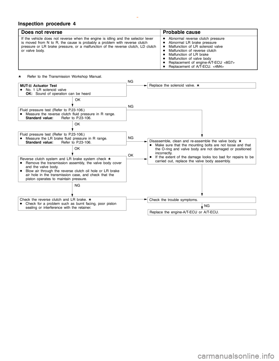
AUTOMATIC TRANSMISSION -Troubleshooting AUTOMATIC TRANSMISSION -Troubleshooting 23-51
Inspection procedure 5
Does not move (forward or reverse)
Probable cause
If the vehicle does not move forward or reverse when the selector lever is
moved to any position while the engine is idling, thecause is probably a
problem with line pressure or a malfunction of the oil pumps and valve bodies in
the power train.DAbnormal line pressure
DMalfunction of power train components
DMalfunction of oil pump
DMalfunction of valve body
DMalfunction of engine-A/T-ECU <6G7>
DMalfunction of A/T-ECU<4M4>
LRefer to the Transmission Workshop Manual.
Fluid pressure test (Refer to P.23-106.)
DMeasure the fluid pressure at each element in 1st, 2nd
and reverse.
Standard value:Refer to P.23-106.OKCheck the power train components
L
DDisassemble the transmission and check the condition of
components such as the planetary carrier, output shaft and
differential.
NG
Replace the oil pumpassembly.
L
(The oilpump cannot be disassembled.)
Disassemble, clean and re-assemble the valve body.
L
DMake sure that the mounting bolts are not loose and that
the O-ring and valve body are notdamaged or positioned
incorrectly.
DIf the extent of thedamagelooks too bad for repairs to be
carried out, replace the valve body assembly.NG
NG
Check the trouble symptoms.
Replace the engine-A/T-ECU or A/T-ECU.
Inspection procedure 6
Engine stalls during shifting
Probable cause
If the enginestalls when the selector lever is moved from N to D or R while the
engine is idling, thecause is probably a malfunction of theenginesystem, DCC
solenoid valve, valve body, or torque converter (damper clutch).DMalfunction of enginesystem
DMalfunction of DCC solenoid valve
DMalfunction of valve body
DMalfunction of torque converter (malfunction of
damper clutch)
DMalfunction of engine-A/T-ECU <6G7>
DMalfunction of A/T-ECU<4M4>
LRefer to the Transmission Workshop Manual.
Engine system check
DControl system, ignition system, fuel system, vehicle bodyNG
Repair or replace
OK
Replace the DCC solenoid valve.
L
Disassemble, clean and re-assemble the valve body.
L
DMake sure that the mounting bolts are not loose and that
the O-ring and valve body are notdamaged or positioned
incorrectly.
DIf the extent of thedamagelooks too bad for repairs to be
carried out, replace the valve body assembly.NGReplace the torque converter assembly.
Check the trouble symptoms.
Replace the engine-A/T-ECU or A/T-ECU.NG
www.WorkshopManuals.co.uk
Purchased from www.WorkshopManuals.co.uk
Page 953 of 1839