oil change MITSUBISHI MONTERO 2000 Service Repair Manual
[x] Cancel search | Manufacturer: MITSUBISHI, Model Year: 2000, Model line: MONTERO, Model: MITSUBISHI MONTERO 2000Pages: 1839, PDF Size: 29.19 MB
Page 124 of 1839

11B-1
ENGINE <4D5>
CONTENTS
GENERAL 2.................................
Outline of Changes 2...........................
GENERAL INFORMATION 2..................
SERVICE SPECIFICATIONS 2.................
SEALANT 2..................................
SPECIAL TOOLS 3...........................ON-VEHICLE SERVICE 4.....................
Injection Timing Check and Adjustment 4.........
Idle Speed Check 4............................
OIL PAN AND OIL SCREEN 5................
TIMING BELT AND TIMING BELT B 7........
CYLINDER HEAD GASKET 13................
www.WorkshopManuals.co.uk
Purchased from www.WorkshopManuals.co.uk
Page 125 of 1839

ENGINE <4D5> -General/General Information/Service Specifications/Sealant11B-2
GENERAL
OUTLINE OF CHANGES
Some service procedures have been revised as the following changes have been made to comply to
the Emission Regulation StepIII.
DInjection timing and idle speed check and adjustment have bee changed as the electronic-controlled
fuel injection pump has been introduced.
DThe oil pan has a cover in order to reduce noise due to an enhanced engine output.
DA crank angle sensor and crankshaft sensing blade have been added due to the introduction of
an electronic-controlled fuel injection pump. Due to this change, the timing belt front lower cover
has been reshaped.
DThe tightening torque of the cylinder head bolts and the cylinder head gasket have been changed.
GENERAL INFORMATION
Items4D56
Total displacement mL2,477
Bore x Stroke mm91.1 x 95.0
Compression ratio21
Combustion chamberVortex chamber type
Camshaft arrangementSOHC
Number of valveIntake4
Exhaust4
Valve timingIntakeOpeningBTDC 20_
ExhaustClosingABDC 49_
IntakeOpeningBBDC 55_
ExhaustClosingATDC 22_
Fuel systemElectronically controlled type injection pump
Rocker armRoller type
Adjusting screwElephant foot type
SERVICE SPECIFICATIONS
ItemsStandard value
Idle speed r/min750±30
Timing belt tension mm4-5
Timing belt B tension mm4-5
SEALANT
ItemsSpecified sealantRemarks
Oil panMITSUBISHI GENUINE PART
MD970389 or equivalentSemi-drying sealant
www.WorkshopManuals.co.uk
Purchased from www.WorkshopManuals.co.uk
Page 214 of 1839

Engine Lubrication -General/Lubricant12-1
GROUP 12
ENGINE LUBRICATION
GENERAL
OUTLINE OF CHANGE
DThe engine oil quantity has been changed as variable geometry (VG) turbocharger has been used.
LUBRICANT
Items4D5Items4D5
Engine oil quantity LOil filter0.8
Oil cooler0.4
Total7.5
www.WorkshopManuals.co.uk
Purchased from www.WorkshopManuals.co.uk
Page 268 of 1839

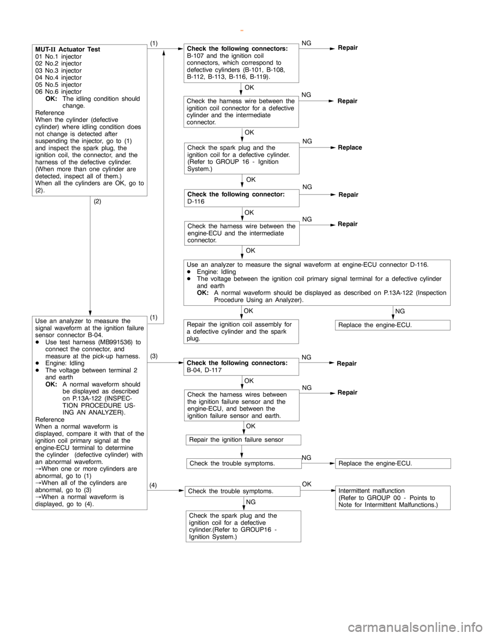
GDI -Troubleshooting
OK
Check the harness wire between the
engine-ECU and the intermediate
connector.NG
Repair
OK
Check the following connector:
D-116NG
Repair
OK
Check the harness wire between the
ignition coil connector for a defective
cylinder and the intermediate
connector.NG
Repair
MUT-
IIActuator Test
01 No.1 injector
02 No.2 injector
03 No.3 injector
04 No.4 injector
05 No.5 injector
06 No.6 injector
OK:
The idling condition should
change.
Reference
When the cylinder (defective
cylinder) whereidling conditiondoes
not change is detected after
suspending the injector, go to (1)
and inspect the spark plug, the
ignition coil, the connector, and the
harness of the defective cylinder.
(When more than one cylinder are
detected, inspect all of them.)
When all the cylinders are OK, go to
(2).(1)Check the following connectors:
B-107 and the ignition coil
connectors, which correspond to
defective cylinders (B-101, B-108,
B-112, B-113, B-116, B-119).NG
Repair
OK
Check the sparkplug and the
ignition coil for a defective cylinder.
(Refer to GROUP 16 - Ignition
System.)NG
Replace
OK
Use an analyzer to measure the signal waveform at engine-ECU connector D-116.
DEngine: Idling
DThe voltage between the ignition coil primary signal terminal for a defective cylinder
and earth
OK:
A normal waveform should be displayed as described on P.13A-122 (Inspection
Procedure Using an Analyzer).
OK
Repair the ignition coil assembly for
a defective cylinder and the spark
plug.
NG
Replace the engine-ECU.
(2)
Use an analyzer to measure the
signal waveform at the ignition failure
sensor connector B-04.
DUse test harness (MB991536) to
connect the connector, and
measure at the pick-up harness.
DEngine: Idling
DThe voltage between terminal 2
and earth
OK:
A normal waveform should
be displayed as described
on P.13A-122 (INSPEC-
TION PROCEDURE US-
ING AN ANALYZER).
Reference
When a normal waveform is
displayed, compare it with that of the
ignition coil primary signal at the
engine-ECU terminal to determine
the cylinder (defective cylinder) with
an abnormal waveform.
®When one or more cylinders are
abnormal, go to (1)
®When all of the cylinders are
abnormal, go to (3)
®When a normal waveform is
displayed, go to (4).(3)
Check the following connectors:
B-04, D-117NG
Repair
OK
Check the harness wires between
the ignition failure sensor and the
engine-ECU, and between the
ignition failure sensor and earth.NG
Repair
OK
Repair the ignition failure sensor
Check the trouble symptoms.NGReplace the engine-ECU.
(4)Check the trouble symptoms.OKIntermittent malfunction
(Refer to GROUP 00 - Points to
Note for Intermittent Malfunctions.)
NG
Check the sparkplug and the
ignition coil for a defective
cylinder.(Refer to GROUP16 -
Ignition System.)
(1)
www.WorkshopManuals.co.uk
Purchased from www.WorkshopManuals.co.uk
Page 274 of 1839

GDI -Troubleshooting
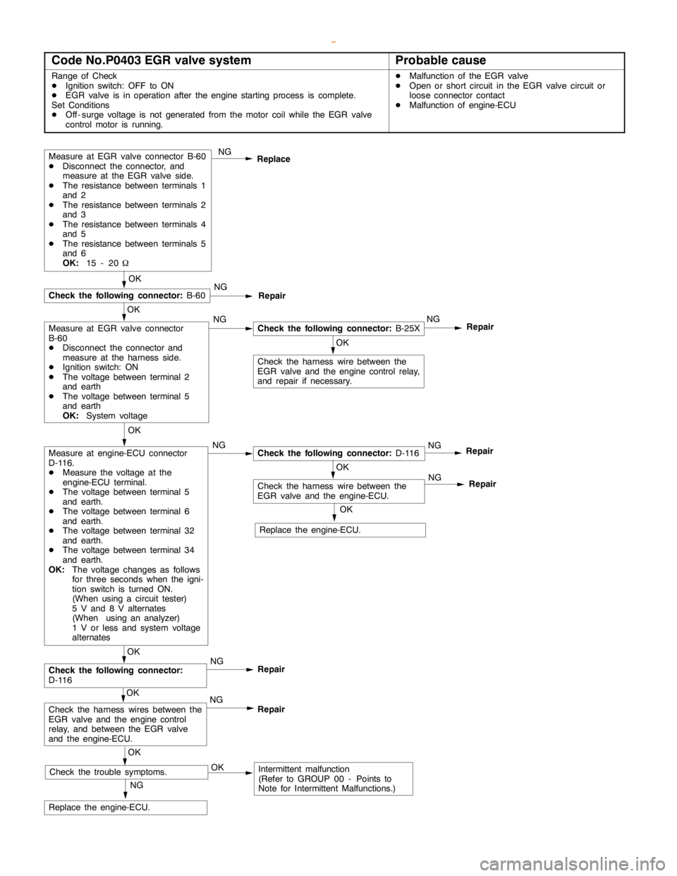
Code No.P0403 EGR valve systemProbable cause
Range of Check
DIgnition switch: OFF to ON
DEGR valve is in operation after theengine startingprocess is complete.
Set Conditions
DOff - surge voltage is not generated from the motor coil while the EGR valve
control motor is running.DMalfunction of the EGR valve
DOpen or short circuit in the EGR valve circuit or
loose connector contact
DMalfunction of engine-ECU
Measure at EGR valve connector B-60
DDisconnect the connector, and
measure at the EGR valve side.
DThe resistance between terminals 1
and 2
DThe resistance between terminals 2
and 3
DThe resistance between terminals 4
and 5
DThe resistance between terminals 5
and 6
OK:
15 - 20WNG
Replace
OK
Check the harness wire between the
EGR valve and theengine controlrelay,
and repair if necessary.
NG
Replace the engine-ECU.
OK
NG
Check the following connector:
B-25XNG
Repair
OK
Check the following connector:
B-60NG
Repair
OK
Measure at engine-ECU connector
D-116.
DMeasure the voltage at the
engine-ECU terminal.
DThe voltage between terminal 5
and earth.
DThe voltage between terminal 6
and earth.
DThe voltage between terminal 32
and earth.
DThe voltage between terminal 34
and earth.
OK:
The voltage changes as follows
for three seconds when the igni-
tion switch is turned ON.
(When using a circuit tester)
5 V and 8 V alternates
(When using an analyzer)
1 V or less and system voltage
alternatesNGCheck the following connector:
D-116NG
Repair
OK
Check the harness wire between the
EGR valve and the engine-ECU.
OK
Check the following connector:
D-116NG
Repair
OK
Check the harness wires between the
EGR valve and theengine control
relay, and between the EGR valve
and the engine-ECU.NG
Repair
OK
Check the trouble symptoms.OKIntermittent malfunction
(Refer to GROUP 00 - Points to
Note for Intermittent Malfunctions.)NG
Repair
OK
Replace the engine-ECU.
Measure at EGR valve connector
B-60
DDisconnect the connector and
measure at the harness side.
DIgnition switch: ON
DThe voltage between terminal 2
and earth
DThe voltage between terminal 5
and earth
OK:
System voltage
www.WorkshopManuals.co.uk
Purchased from www.WorkshopManuals.co.uk
Page 902 of 1839

Page 1805 of 1839

HEATER, AIR CONDITIONER AND VENTILATION -Service Specifications/Lubricants55B-2
SERVICE SPECIFICATIONS
ItemStandard value
Resistance value of the potentiometer for the air mix damper (front A/C) kWApprox. 0.96 - 5.76
Resistance value of the potentiometer for the air outlet changeover damper (front A/C)
kWApprox. 0.96 - 5.76
Resistance of the rear air conditioner switch (temperature control switch)
Resistance of the potentiometer for the air mix damper
Resistance value of the resistor (rear A/C)Between terminals 1 and 64.9±7%
WBetween terminals 1 and 31.25±7%
Air compressor air gap mm0.35 - 0.65
Idle speed r/min (N or P range)Petrol600±50
Idle-up speed r/min (N or P range)PetrolWhen the A/C is under
low load700±50
When the A/C is under
medium load800±50
When the A/C is under
high load1,000±50
LUBRICANTS
ItemBrandQuantity
Compressor oil mlSingle A/C
Single air conditioner
Pipe connectionsDENSO OIL 8As required
Refrigerant gSingle A/C
Single air conditioner
www.WorkshopManuals.co.uk
Purchased from www.WorkshopManuals.co.uk