ESP MITSUBISHI OUTLANDER 2020 (in English) User Guide
[x] Cancel search | Manufacturer: MITSUBISHI, Model Year: 2020, Model line: OUTLANDER, Model: MITSUBISHI OUTLANDER 2020Pages: 443, PDF Size: 60.03 MB
Page 123 of 443

Power liftgate (if so equipped) 5-42 Features and controls
5
N00575900026
Before operating the po
wer liftga
te, unlock
the power liftgate by pushing the power doorlock switch or the unlock button on the key- less entry system or F.A.S.T.-key. Refer to “Keyless entry system”, “Free-handAdvanced Security Transmitter (F.A.S.T.- key)” and “Power door locks” on pages 5-7, 5-15 and 5-38 respectively.
N00576000037
Power liftgate
(if so equipped)
Operating the power liftgate
WA R N I N G The luggage area was
not designed for
people to ride in. Do not let your children ride in or play in
the luggage area. Riding
or playing in the luggage area could result in a serious accide
nt and/or injury.
Before driving, make sure the power lift- gate is securely closed. If you drive with th
e power liftgate open,
exhaust gas may enter the vehicle and cause carbon monoxide poisoning. To avoid injury, the power liftgate should not be operated by children.
When opening and cl
osing the power lift-
gate, make sure that there are no peoplenearby and be careful not to hit your heador pinch your hands, neck, etc. Make sure the power liftgate is completely open before loadin
g and unloading lug-
gage.CAUTION Do not stand behind the exhaust pipe when loading and unloading luggage. The heat from the exha
ust could cause burns.
Before driving, make sure the power liftgate is securely closed. If
the liftgate opens while
driving, objects stored in the luggage com-partment coul
d fall out into the road.
Do not install any accessory other than Mit- subishi Motors Genui
ne parts on the power
liftgate. The weight of the accessory may cause faulty operati
on of the liftgate.
Before closing the liftga
te, make sure there is
no foreign object around
the striker (A).
If a foreign object matter
gets into the striker,
it could prevent the pow
er liftgate from clos-
ing securely.WA R N I N G
NOTE
When opening and closing the power lift- gate, do not place your
hands near the arm
(B) and gas struts (C). To prevent damage to the gas struts: • Do not push or pull on the gas struts. • Do not wrap, attach or hang anything on the gas struts.
BK0278200US.book 42 ページ 2019年4月10日 水曜日 午前10時59分
Page 128 of 443
Power liftgate (if so equipped) Features and controls 5-47
5
If the engine is started while the power lift- gate is operating, the power liftgate may intermittently move or stop moving to pre- vent the power liftgate from moving abruptly.Approximately 10 seconds after the power liftgate has fully closed or opened, power lift- gate operation will again resume.
N00576300030
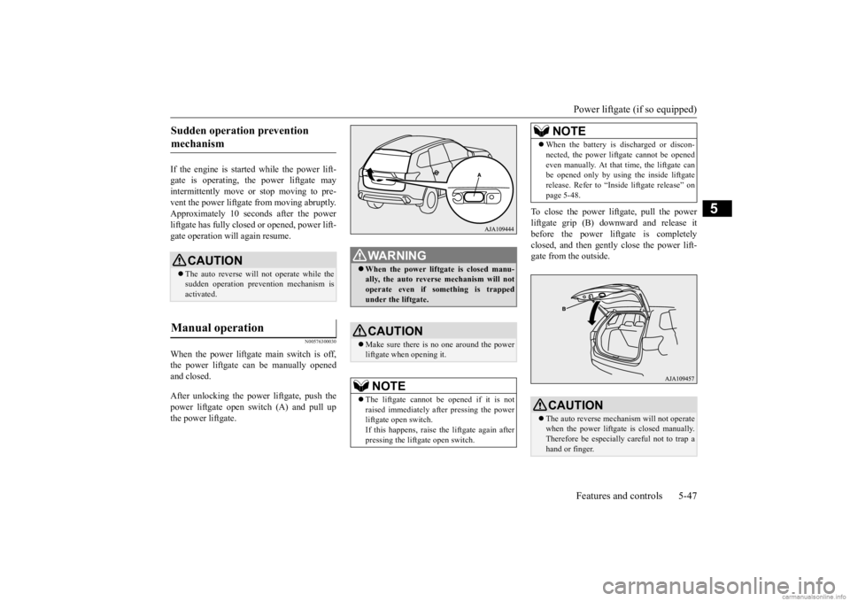
When the power liftgate main switch is off,the power liftgate can be manually openedand closed. After unlocking the power liftgate, push the power liftgate open switch (A) and pull up the power liftgate.
To close the power liftgate, pull the power liftgate grip (B) do
wnward and release it
before the power liftgate is completely closed, and then gently close the power lift- gate from the outside.
Sudden operation prevention mechanism
CAUTION The auto reverse will not operate while the sudden operation prev
ention mechanism is
activated.
Manual operation
WA R N I N G When the power liftgate is closed manu- ally, the auto reverse mechanism will notoperate even if something is trapped under the liftgate.CAUTION Make sure there is no one around the power liftgate when
opening it.
NOTE
The liftgate cannot be
opened if it is not
raised immediately after pressing the powerliftgate open switch. If this happens, raise th
e liftgate again after
pressing the liftgate open switch.
When the battery is discharged or discon- nected, the power lift
gate cannot be opened
even manually. At that time, the liftgate canbe opened only by using
the inside liftgate
release. Refer to “Inside liftgate release” on page 5-48.CAUTION The auto reverse mechanism will not operate when the power liftgate
is closed manually.
Therefore be especially
careful not to trap a
hand or finger.NOTE
BK0278200US.book 47 ページ 2019年4月10日 水曜日 午前10時59分
Page 133 of 443
Power window control 5-52 Features and controls
5
N00548701212
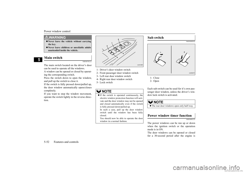
The main switch located on the driver’s door can be used to operate all the windows. A window can be opened or closed by operat-ing the corresponding switch. Press the switch down to open the window, and pull up the switch to close it.If the switch is fully pressed down/pulled up, the door window automatically opens/closes completely.If you want to stop the window movement, operate the switch lightly in the reverse direc- tion.
N00548800102
Each sub-switch can be
used for it’s own pas-
senger door window, unless the driver’s win-dow lock switch is activated.
N00548901155
The power windows can be run up or downwhen the ignition switch or the operationmode is in ON. The door windows can be opened or closed for a 30-second period after the engine is
Never leave the vehi
cle without carrying
the key. Never leave children
or unreliable adults
unattended inside the vehicle.
Main switch
WA R N I N G
1- Driver’s door window switch 2- Front passenger door window switch 3- Left rear door window switch 4- Right rear door window switch5- Lock switch
NOTE
If the switch is operated continuously, the electric window protecti
on function wi
ll acti-
vate and the door window may not be opened and closed automatically even if the switch is fully pressed down/pulled up.In such a case, pull up the door window switch until the wi
ndow has been fully
closed.You should now be able to operate the door window in a normal fashion.
Sub switch 1- Close 2- Open
NOTE
The rear door windows open only half-way.
Power window timer function
BK0278200US.book 52 ページ 2019年4月10日 水曜日 午前10時59分
Page 134 of 443
Power window control
Features and controls 5-53
5
stopped. However, once the driver’s door or the front passenger’s
door is opened, the
power windows cannot be operated.
N00549001166
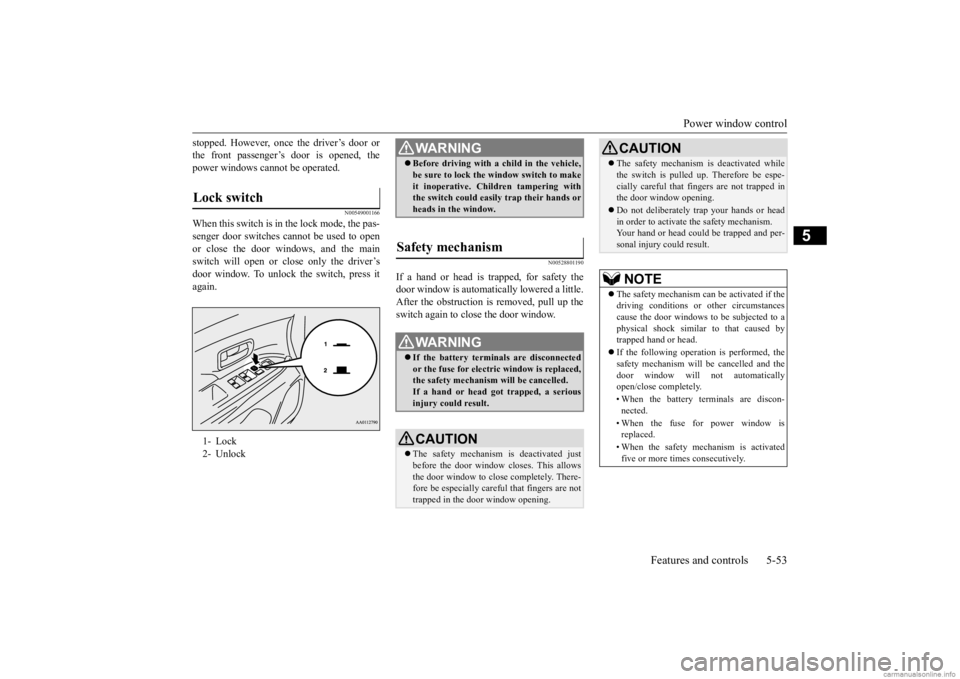
When this switch is in the lock mode, the pas-senger door switches cannot be used to open or close the door windows, and the main switch will open or close only the driver’s door window. To unlock the switch, press it again.
N00528801190
If a hand or head is trapped, for safety thedoor window is automatically lowered a little.After the obstruction is
removed, pull up the
switch again to close the door window.
Lock switch 1- Lock 2- Unlock
WA R N I N G Before driving with a child in the vehicle, be sure to lock the window switch to makeit inoperative. Children tampering withthe switch could easily trap their hands or heads in the window.
Safety mechanism
WA R N I N G If the battery terminals are disconnected or the fuse for electric window is replaced,the safety mechanism will be cancelled. If a hand or head got
trapped, a serious
injury could result.CAUTION The safety mechanism is deactivated just before the door window closes. This allowsthe door window to close completely. There- fore be especially careful that fingers are not trapped in the door window opening.
The safety mechanism is deactivated while the switch is pulled up.
Therefore be espe-
cially careful that fi
ngers are not trapped in
the door window opening. Do not deliberately tr
ap your hands or head
in order to activate the safety mechanism. Your hand or head coul
d be trapped and per-
sonal injury could result.NOTE
The safety mechanism can be activated if the driving conditions or
other circumstances
cause the door windows to
be subjected to a
physical shock similar
to that caused by
trapped hand or head. If the following operation is performed, the safety mechanism will
be cancelled and the
door window will not
automatically
open/close completely. • When the battery terminals are discon- nected. • When the fuse for power window is replaced. • When the safety mechanism is activated five or more times consecutively.CAUTION
BK0278200US.book 53 ページ 2019年4月10日 水曜日 午前10時59分
Page 136 of 443
Sunroof (if so equipped)
Features and controls 5-55
5
be operated. Turn on the ignition switch again to operate. If a hand or head is trapped in the closing sunroof opening, the safety mechanism willcause the sunroof to re-open automatically. The opened sunroof will
become operational
again after a few seconds. If the safety mechanism is activated 5 or more times consecutively, normal closing of the sunroof will be aborted. As an emergency measure, the sunroof can beclosed bit by bit until the sunroof is com- pletely closed by re
peatedly pressing the
switch (2).After that, the sunroof can be set the initial- ized state in the following procedure. 1. Move the sunroof in slide open position. 2. Press the tilt up switch (2) continually in10 seconds. 3. The sunroof will be
moved to tilt up posi-
tion automatically bit by bit.4. The initialize is completed when the sun- roof is stopped at
tilt up position.
If the sunroof does not return to normal,consult an authoriz
ed Mitsubishi Motors
dealer.
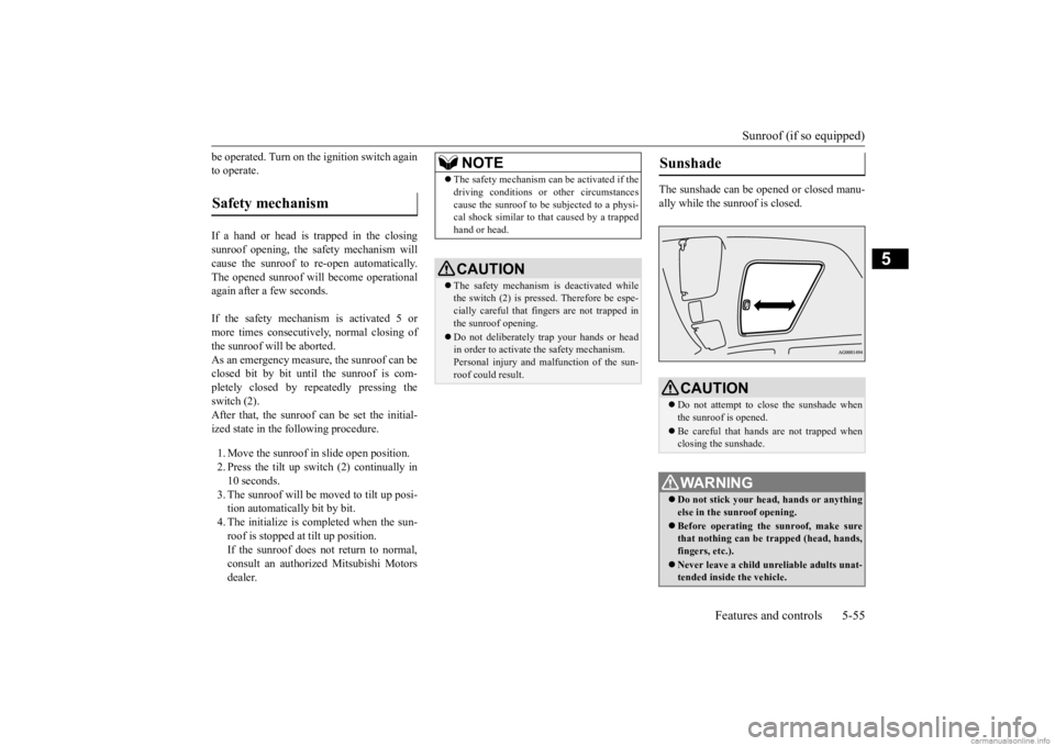
The sunshade can be opened or closed manu- ally while the sunroof is closed.
Safety mechanism
NOTE
The safety mechanism can be activated if the driving conditions or
other circumstances
cause the sunroof to be
subjected to a physi-
cal shock similar to th
at caused by a trapped
hand or head.CAUTION The safety mechanism is deactivated while the switch (2) is pressed. Therefore be espe-cially careful that fi
ngers are not trapped in
the sunroof opening. Do not deliberately trap your hands or head in order to activate the safety mechanism. Personal injury and malfunction of the sun-roof could result.
Sunshade
CAUTION Do not attempt to close the sunshade when the sunroof is opened. Be careful that hands
are not trapped when
closing the sunshade.WA R N I N G Do not stick your head
, hands or anything
else in the su
nroof opening.
Before operating the sunroof, make sure that nothing can be trapped (head, hands, fingers, etc.). Never leave a child unr
eliable adults unat-
tended inside the vehicle.
BK0278200US.book 55 ページ 2019年4月10日 水曜日 午前10時59分
Page 156 of 443
Automatic transaxle (if so equipped)
Features and controls 5-75
5
N00538801193
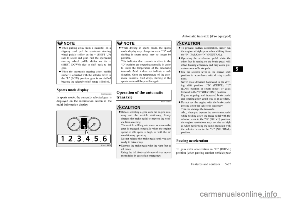
In sports mode, the curre
ntly selected gear is
displayed on the information screen in the multi-information display.
N00514501372
To gain extra acceleration in “D” (DRIVE)position (when passing another vehicle) push
When pulling away from a standstill on a slippery road, pull the sportronic steeringwheel paddle shifter on the + (SHIFT UP)side to select 2nd gear
. Pull the sportronic
steering wheel paddle shifter on the
−
(SHIFT DOWN) side to shift back to 1stgear. When the sportronic steering wheel paddle shifter is operated with the selector lever in the “L” (LOW) position, gear is not shifted because the selectable shift range is limited.
Sports mode display
NOTE
NOTE
While driving in sports mode, the sports mode display may change to show “D” andshifting in sports mode may no longer bepossible. This indicates that controls to drive in the “D” position are operati
ng normally in order
to lower the temperature of the automatic transaxle fluid; it doe
s not indicate a mal-
function. Once the temperature of the auto-matic transaxle fluid drops, shifting in the sports mode will be possible again.
Operation of the automatic transaxle
CAUTION Before selecting a gear
with the engine run-
ning and the vehicle
stationary, firmly
depress the brake pedal to prevent the vehi-cle from creeping. The vehicle will begin to
move as soon as the
gear is engaged, espe
cially when the engine
speed or idle speed is
high, or with the air
conditioning operating. Do not release the brake pedal until you are ready to drive away. Depress the brake pedal with the right foot at all times.Using the left foot c
ould cause driver move-
ment delay in case of an emergency.
To prevent sudden acce
leration, never run
the engine at high rpms when shifting fromthe “P” (PARK) or “N” (NEUTRAL). Operating the accelerator pedal while the other foot is resting
on the brake pedal will
affect braking efficiency and may cause pre- mature wear of brake pads. Use the selector lever in the correct shift position in accordance
with driving condi-
tions.Never coast downhill backward in the driv- ing shift position {“D” (DRIVE), “L” (LOW) position or sports mode} or coastforward in the “R” (REVERSE) position. Engine stopping and increased brake pedal and steering effort could
lead to an accident.
Do not rev the engine
with the brake pedal
pressed when the vehicle is stationary.This can damage the transaxle. Also, when you depress
the accelerator pedal
while holding down the brake pedal with theselector lever in th
e “D” (DRIVE) position,
the engine revolutions
may not rise as high
as when performing the same operation withthe selector lever in the “N” (NEUTRAL) position.
Passing acceleration
CAUTION
BK0278200US.book 75 ページ 2019年4月10日 水曜日 午前10時59分
Page 163 of 443
Continuously variable transmission (CVT) (if so equipped) 5-82 Features and controls
5
N00560901113
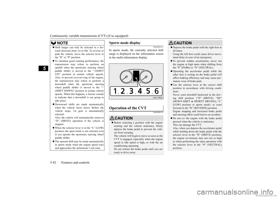
In sports mode, the currently selected shift range is displayed on
the information screen
in the multi-information display.
N00560801125
NOTE
Shift ranges can only be
selected in a for-
ward direction from 1st to 6th. To reverse orpark the vehicle, move
the selector lever to
the “R” or “P” position. To maintain good running performance, the transmission may refuse to perform an upshift when the sportronic steering wheel paddle shifter is moved to the “+(SHIFTUP)” position at cert
ain vehicle speeds.
Also, to prevent over-revving of the engine, the transmission may refuse to perform adownshift when the
sportronic steering
wheel paddle shifter is moved to the “
−
(SHIFT DOWN)” position
at certain vehicle
speeds. When this happens, a buzzer sounds to indicate that a dow
nshift is not going to
take place. Downward shifts are made automatically when the vehicle slows down. Before thevehicle stops, 1st ge
ar is automatically
selected. Also, the vehicle will automatically return to“D” (DRIVE) operation if the vehicle is stopped. When the selector lever is in the “L” (LOW) position, the sport mode
is not selected even
if you operate the spor
tronic steering wheel
paddle shifter. The upward shift may be
made automatically
in sports mode when the engine speed rises and approaches the tachometer’s red zone.
Sports mode display
Operation of the CVT
CAUTION Before selecting a pos
ition with the engine
running and the vehicl
e stationary, firmly
depress the brake pedal to prevent the vehi-cle from creeping. The vehicle will begin to move as soon as the CVT is engaged,
especially when the engine
speed or idle speed is
high, or with the air
conditioning operating. Do not release the brak
e pedal until you are
ready to drive away.
Depress the brake pedal with the right foot at all times.Using the left foot c
ould cause driver move-
ment delay in case of an emergency. To prevent sudden acceleration, never run the engine at high rpms when shifting from the “P” (PARK) or “N” (NEUTRAL). Operating the accelerator pedal while the other foot is resting
on the brake pedal will
affect braking efficien
cy and may cause pre-
mature wear of brake pads. Use the selector lever in the correct shift position in accordance
with driving condi-
tions. Never coast downhill backward in the driv-ing shift position {“D” (DRIVE), “DS” (DOWN SHIFT & SPORTY DRVING), “L” (LOW) position or sports mode} or coastforward in the “R” (REVERSE) position. Engine stopping and in
creased brake pedal
and steering effort could
lead to an accident.
Do not rev the engine
with the brake pedal
pressed when the vehi
cle is stationary.
This can damage the CVT. Also, when you depress
the accelera
tor pedal
while holding down the brake pedal with theselector lever in the “D” (DRIVE) position, the engine revolutions
may not rise as high
as when performing the same operation withthe selector lever in the “N” (NEUTRAL) position.CAUTION
BK0278200US.book 82 ページ 2019年4月10日 水曜日 午前10時59分
Page 167 of 443
S-AWC (Super-All Wheel Control) (if so equipped) 5-86 Features and controls
5
The electronically controlled 4WD is a sys- tem that improves acceleration performance and stability performance by controlling front-rear distribution of
driving torque with
operating the electroni
c control coupling
arranged in the rear differential assembly. The AYC is a system with a yaw control function, that controls the left-right driv- ing/braking force using the brakes.
The yaw control function is a function that enhances vehicle cornering performance and vehicle stability with
management of vehicle
turning power (yaw moment) by controlling the drive power difference of the left and right wheels and the braking force when thevehicle does not turn in
response to steering
input, such as when the steering wheel is turned quickly or when driving on slippery road.
N00542401103
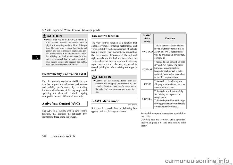
Select the drive mode from the following fourtypes to suit the driving conditions.
4-wheel drive operation requires special driv- ing skills. Carefully read the “4-wheel drive operation” section on page 5-88 and take care to drivesafety.
CAUTION Do not over-rely on the S-AWC. Even the S- AWC cannot prevent the natural laws ofphysics from acting on the vehicle. This sys-tem, like any other sy
stem, has limits and
cannot help you to main
tain traction and con-
trol of the vehicle in
all circumstances. Reck-
less driving can lead to
accidents. It is the
driver’s responsibility to drive carefully. This means taking into account the traffic,road and environmental conditions.
Electronically Controlled 4WD
Active Yaw Control (AYC)
Yaw control function
CAUTION Control of the braking force does not enhance the stopping performance of thevehicle, therefore, pa
y careful attention to
the safety of your surroundings when driv- ing.
S-AWC drive mode
S-AWC drive mode
Function
AW C E C O
This is the most fuel efficient mode. Normal operation is in 2WD, but 4WD performance will be provided under slippery conditions.
NORMAL
This mode can be used on both dry and wet roads. The distri- bution of driving/braking torque to each wheel is auto-matically controlled according to the driving condition.
SNOW
This mode is for driving on slippery road surfaces, such as snow-covered roads.
GRAVEL
This mode is suitable mainly for driving on unpaved or rough roads.This mode provides 4WD high driving performance and stable cornering performance.
BK0278200US.book 86 ページ 2019年4月10日 水曜日 午前10時59分
Page 170 of 443
4-wheel drive operation
Features and controls 5-89
5
tion when driving on sl
ippery, wet or snow-
covered roads and when moving out of mud.But it is not suitable
for heavy off road use or
towing in rough conditions. It is particularly im
portant to note that 4-
wheel drive may not give sufficient hill climbing ability and engine braking on steep slopes. You should try to avoid driving onsteep slopes. Also, you must exercise caution when driving on sand and mud and when driving through water because sufficie
nt traction may not be
available in certain circumstances.Please avoid driving the vehicle through areas where the tires may get stuck in deep sand or mud.
When turning a sharp corner in “4WD LOCK” (Electronically controlled 4WD) or“GRAVEL” (S-AWC) position at low speed, a slight difference in
steering may be experi-
enced similar to feeling as if the brakes wereapplied. This is called tight corner braking and results from each of the four tires being at a different distance from the corner. The phe-nomenon is typical of 4-wheel drive vehicles. If this occurs, either straighten out the steer- ing wheel or change to another mode. Set the drive mode-selector to “4WD AUTO”, “4WD LOCK” (Electronically con-trolled 4WD) or “SNOW” (S-AWC) in accor- dance with the road conditions, and then gradually depress the ac
celerator pedal for a
smooth start.
WA R N I N G Do not over-rely on th
e 4-wheel drive vehi-
cles. Even 4-wheel drive vehicles have lim- its to the system and ability to maintaincontrol and traction.
Reckless driving may
lead to accidents. Always drive carefully, taking account of the road conditions. Improperly operating
this vehicle on or
off-pavement can cause an accident orrollover in which you
and your passengers
could be seriously
injured or killed.
• Follow all instructions and guidelines in the owner’s manual.• Keep your speed low and do not drivefaster than conditions.
NOTE
Driving on rough roads can be hard on a vehicle. Before you le
ave the pavement, be
sure all scheduled ma
intenance and service
has been done, and that
you have inspected
your vehicle. Pay spec
ial attenti
on to the
condition of the tires, a
nd check the tire pres-
sures. Mitsubishi Motors is not
responsible to the
operator for any damage or injury caused or liability incurred by improper and negligent operation of a vehicl
e. All techniques of
vehicle operation depe
nd on the skill and
experience of the oper
ator and other partici-
pating parties. Any de
viation from the rec-
ommended operating instru
ctions above is at
their own risk. Note that the stopping distance required of the 4-wheel drive vehicl
e differs very little
from that of the front-wheel drive vehicle.When driving on a snow-covered road or a slippery, muddy surface,
make sure that you
keep a sufficient dist
ance between your vehi-
cle and the one ahead of you. The driving posture should be more upright; adjust the seat to a good position for easy steering and pedal operati
on. Be sure to wear
the seat belt. After driving on rough roads, check each part of the vehicle and wash it thoroughlywith water. Refer to the “Inspection and maintenance following rough road opera- tion” section and “Vehic
le care and Mainte-
nance” sections.
CAUTION Setting the drive mode-selector to “4WD LOCK” (Electronically
controlled 4WD) or
“GRAVEL” (S-AWC) position to drive ondry paved road will in
crease fuel consump-
tion, with possible
noise generation.
Turning sharp corners On snowy or icy roads
BK0278200US.book 89 ページ 2019年4月10日 水曜日 午前10時59分
Page 173 of 443
Service brake 5-92 Features and controls
5
N00517500275
Overuse of the brake can cause weakening, resulting in poor brake response and prema- ture wear of the brake pads.When driving down a long or steep hill, use engine braking by downshifting.
CAUTION Always use tires of th
e same size, type, and
brand that have no wear differences. Usingtires of different size, type, brands or degreeof wear, will increase the differential oil tem- perature and result in possible damage to the driving system. Further, the drive train willbe subject to excessi
ve loading, possibly
leading to oil leakage,
component seizure, or
other serious failures.
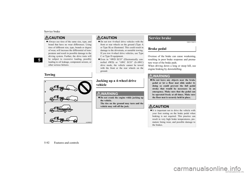
To w i n g
CAUTION Do not tow 4-wheel drive vehicles with the front or rear wheels on the ground (Type Aor Type B) as illustrated. This could result indamage to the drivetra
in, or unstable towing.
If you tow 4-wheel drive vehicles, use Type C or Type D equipment. Even in “4WD ECO” (Electronically con- trolled 4WD) or “AWC ECO” (S-AWC)drive mode, the vehicle cannot be towed with the front or the rear wheels on the ground.
Jacking up a 4-wheel drive vehicle
WA R N I N G Do not crank the engine while jacking up the vehicle.The tire on the ground may turn and the vehicle may roll off the jack.
Service brake Brake pedal
WA R N I N G Do not leave any obje
cts near the brake
pedal or let a floor
mat slide under it;
doing so could prevent the full pedalstroke that would be necessary in an emergency. Make sure that the pedal can be operated freely at
all times. Make sure
the floor mat is securely held in place.CAUTION It is important not to drive the vehicle with your foot resting on the brake pedal when braking is not required.
This practice can
result in very high brake temperatures, pre-mature lining wear, a
nd possible damage to
the brakes.
BK0278200US.book 92 ページ 2019年4月10日 水曜日 午前10時59分