MITSUBISHI OUTLANDER PHEV 2016 Owner's Manual (in English)
Manufacturer: MITSUBISHI, Model Year: 2016, Model line: OUTLANDER PHEV, Model: MITSUBISHI OUTLANDER PHEV 2016Pages: 490, PDF Size: 22.02 MB
Page 291 of 490
NOTElIt is not possible to fully see obstacles when
the lens is dirty. If the lens becomes conta-minated by water droplets, snow, mud or oil,
wipe off the contamination, taking care not
to scratch the lens.
l Please observe the following cautions. Ig-
noring them could lead to a camera malfunc- tion.
• Do not subject the camera to physical
shook such as striking it strongly or
throwing a thing.
• Do not adhere organic substances, waxes,
oil remover, and glass cleaner to the cam-
era.
If adhered to them, immediately wipe off.
• Do not splash the camera with boiling wa-
ter.
• Never spray or splash water on the cam-
era or around it.
• Do not disconnect, disassemble or modify
the camera.
• Do not scratch the camera, as this may
cause damage to the camera images.
How to use the Multi Around
Monitor
The Multi Around Monitor can only be used
when the operation mode is ON.
Operation with the selector lev-
er
When you place the select position is the “R”
position, the bird’s eye view/rear view is dis- played on the screen of the inside rear view
mirror or the MITSUBISHI Multi-communi-
cation System (MMCS). When you move the
selector lever to any other position, the dis- play disappears.
NOTEl The passenger’s side screen can be switched
to the side view by pressing the switch.
Operation with the switch
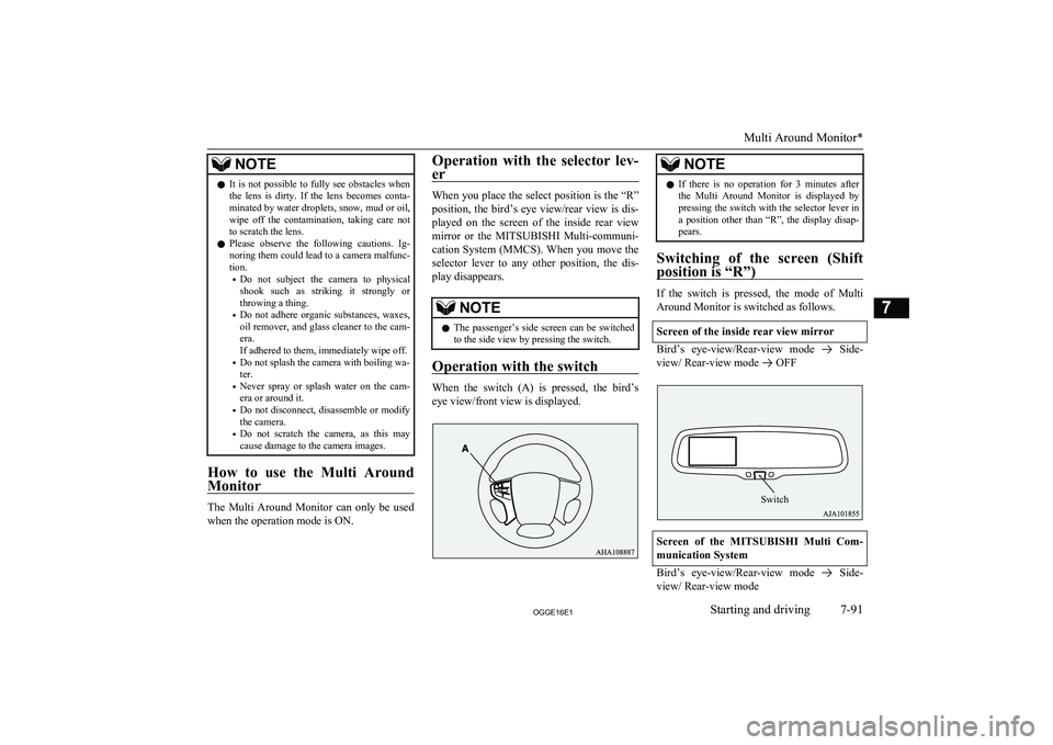
When the switch (A) is pressed, the bird’s
eye view/front view is displayed.
NOTEl If there is no operation for 3 minutes after
the Multi Around Monitor is displayed by pressing the switch with the selector lever in a position other than “R”, the display disap- pears.
Switching of the screen (Shift
position is “R”)
If the switch is pressed, the mode of Multi Around Monitor is switched as follows.
Screen of the inside rear view mirror
Bird’s eye-view/Rear-view mode Side-
view/ Rear-view mode
OFF
Screen of the MITSUBISHI Multi Com-
munication System
Bird’s eye-view/Rear-view mode Side-
view/ Rear-view mode
Multi Around Monitor*
7-91OGGE16E1Starting and driving7 Switch
Page 292 of 490
Switching of the screen (Shift
position is other than “R”)
If the switch is pressed, the mode of Multi Around Monitor is switched, Bird’s eyeview/
Front-view mode
Side-view/Frontview
mode
OFF
NOTEl For the switching of the screen on the
MITSUBISHI Multi Communication Sys-
tem, also refer to the separate owner’s man-
ual.
l When you place the select position is the
“R” position with the front view displayed
on the driver’s side screen, the driver’s side screen switches to the Rear-view mode.
When you move the selector lever to any other position, the driver’s side screen
switches to the Frontview mode.
l When the switch is pressed at the vehicle
speed of about 10 km/h (6 mph) or higher,
only the side view can be displayed on the passenger’s side screen.
l The front view will not be displayed when
the vehicle speed exceeds about 10 km/h
(6 mph).
l The display of the view may be delayed dur-
ing switching of the screen.How to read the screen
E00645400037
In any mode other than the Bird’s eye-view
mode, the lines in the screen give the follow-
ing information. Use them only as a guide.
CAUTIONl When you accidentally hit the camera and its
circumference against something, the view and the lines in the screen may not be dis-played correctly. Be sure to have it inspected
by a MITSUBISHI MOTORS Authorized
Service Point.
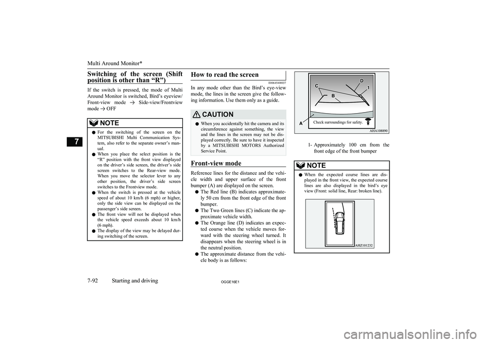
Front-view mode
Reference lines for the distance and the vehi-
cle width and upper surface of the front bumper (A) are displayed on the screen.
l The Red line (B) indicates approximate-
ly 50 cm from the front edge of the front
bumper.
l The Two Green lines (C) indicate the ap-
proximate vehicle width.
l The Orange line (D) indicates an expec-
ted course when the vehicle moves for-
ward with the steering wheel turned. It disappears when the steering wheel is in
the neutral position.
l The approximate distance from the vehi-
cle body is as follows:
1- Approximately 100 cm from the
front edge of the front bumper
NOTEl When the expected course lines are dis-
played in the front view, the expected course lines are also displayed in the bird’s eyeview (Front: solid line, Rear: broken line).
Multi Around Monitor*
7-92OGGE16E1Starting and driving7 Check surroundings for safety.
Page 293 of 490
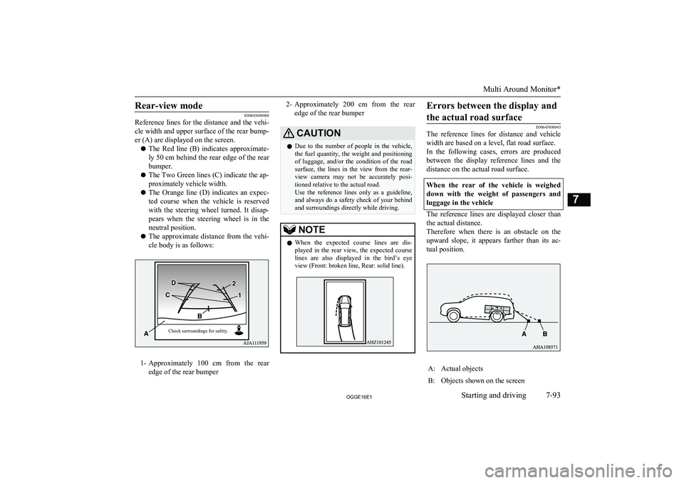
Rear-view mode
E00645600068
Reference lines for the distance and the vehi-
cle width and upper surface of the rear bump-
er (A) are displayed on the screen.
l The Red line (B) indicates approximate-
ly 50 cm behind the rear edge of the rear
bumper.
l The Two Green lines (C) indicate the ap-
proximately vehicle width.
l The Orange line (D) indicates an expec-
ted course when the vehicle is reserved
with the steering wheel turned. It disap- pears when the steering wheel is in the
neutral position.
l The approximate distance from the vehi-
cle body is as follows:
1- Approximately 100 cm from the rear
edge of the rear bumper
2- Approximately 200 cm from the rear
edge of the rear bumperCAUTIONl Due to the number of people in the vehicle,
the fuel quantity, the weight and positioning of luggage, and/or the condition of the roadsurface, the lines in the view from the rear-
view camera may not be accurately posi- tioned relative to the actual road.
Use the reference lines only as a guideline,
and always do a safety check of your behind and surroundings directly while driving.NOTEl When the expected course lines are dis-
played in the rear view, the expected course lines are also displayed in the bird’s eyeview (Front: broken line, Rear: solid line).Errors between the display and
the actual road surface
E00645900045
The reference lines for distance and vehicle
width are based on a level, flat road surface.In the following cases, errors are produced between the display reference lines and the
distance on the actual road surface.
When the rear of the vehicle is weighed down with the weight of passengers and
luggage in the vehicle
The reference lines are displayed closer than the actual distance.
Therefore when there is an obstacle on the
upward slope, it appears farther than its ac-
tual position.
A:Actual objectsB:Objects shown on the screen
Multi Around Monitor*
7-93OGGE16E1Starting and driving7Check surroundings for safety.
Page 294 of 490
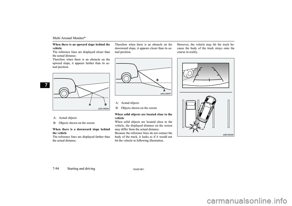
When there is an upward slope behind the
vehicle
The reference lines are displayed closer than the actual distance.
Therefore when there is an obstacle on the
upward slope, it appears farther than its ac-
tual position.A:Actual objectsB:Objects shown on the screen
When there is a downward slope behind
the vehicle
The reference lines are displayed farther than
the actual distance.
Therefore when there is an obstacle on the
downward slope, it appears closer than its ac-
tual position.A:Actual objectsB:Objects shown on the screen
When solid objects are located close to the vehicle
When solid objects are located close to the
vehicle, the displayed distance on the screen
may differ from the actual distance.
Because the reference lines do not contact the body of the truck, it looks as if it would not
hit the vehicle in following illustration.
However, the vehicle may hit the truck be-
cause the body of the truck strays onto the course in reality.
Multi Around Monitor*
7-94OGGE16E1Starting and driving7
Page 295 of 490
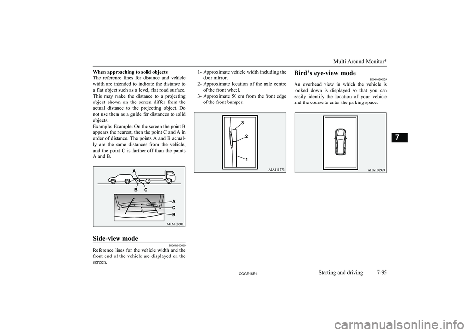
When approaching to solid objects
The reference lines for distance and vehicle
width are intended to indicate the distance to a flat object such as a level, flat road surface. This may make the distance to a projecting
object shown on the screen differ from the
actual distance to the projecting object. Do not use them as a guide for distances to solid
objects.
Example: Example: On the screen the point B appears the nearest, then the point C and A in
order of distance. The points A and B actual-
ly are the same distances from the vehicle,
and the point C is farther off than the points
A and B.Side-view mode
E00646100060
Reference lines for the vehicle width and the front end of the vehicle are displayed on the
screen.
1- Approximate vehicle width including the
door mirror.
2- Approximate location of the axle centre
of the front wheel.
3- Approximate 50 cm from the front edge
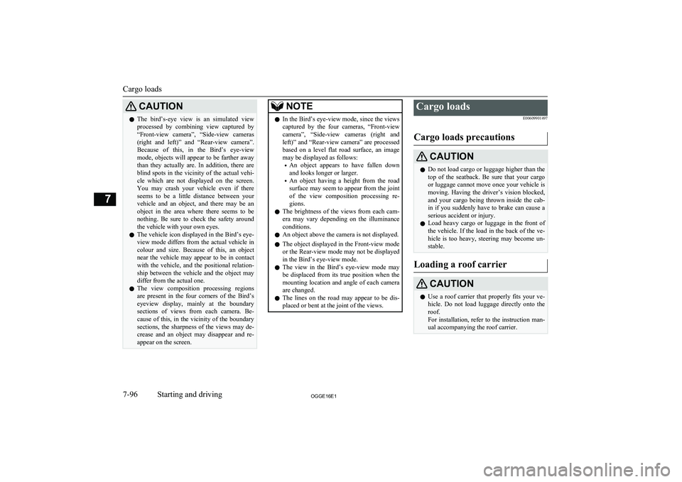
of the front bumper.Bird’s eye-view mode
E00646200029
An overhead view in which the vehicle is
looked down is displayed so that you can
easily identify the location of your vehicle
and the course to enter the parking space.
Multi Around Monitor*
7-95OGGE16E1Starting and driving7
Page 296 of 490
CAUTIONlThe bird’s-eye view is an simulated view
processed by combining view captured by “Front-view camera”, “Side-view cameras(right and left)” and “Rear-view camera”.
Because of this, in the Bird’s eye-view
mode, objects will appear to be farther away than they actually are. In addition, there areblind spots in the vicinity of the actual vehi-
cle which are not displayed on the screen.
You may crash your vehicle even if there
seems to be a little distance between your vehicle and an object, and there may be an
object in the area where there seems to be
nothing. Be sure to check the safety around
the vehicle with your own eyes.
l The vehicle icon displayed in the Bird’s eye-
view mode differs from the actual vehicle in colour and size. Because of this, an object
near the vehicle may appear to be in contact with the vehicle, and the positional relation-ship between the vehicle and the object may
differ from the actual one.
l The view composition processing regions
are present in the four corners of the Bird’s
eyeview display, mainly at the boundary sections of views from each camera. Be-
cause of this, in the vicinity of the boundary sections, the sharpness of the views may de-crease and an object may disappear and re- appear on the screen.NOTEl In the Bird’s eye-view mode, since the views
captured by the four cameras, “Front-view camera”, “Side-view cameras (right and
left)” and “Rear-view camera” are processed based on a level flat road surface, an image
may be displayed as follows:
• An object appears to have fallen down
and looks longer or larger.
• An object having a height from the road
surface may seem to appear from the joint of the view composition processing re-gions.
l The brightness of the views from each cam-
era may vary depending on the illuminance conditions.
l An object above the camera is not displayed.
l The object displayed in the Front-view mode
or the Rear-view mode may not be displayed
in the Bird’s eye-view mode.
l The view in the Bird’s eye-view mode may
be displaced from its true position when the mounting location and angle of each camera are changed.
l The lines on the road may appear to be dis-
placed or bent at the joint of the views.Cargo loads
E00609901497
Cargo loads precautionsCAUTIONl Do not load cargo or luggage higher than the
top of the seatback. Be sure that your cargo
or luggage cannot move once your vehicle is moving. Having the driver’s vision blocked,
and your cargo being thrown inside the cab- in if you suddenly have to brake can cause a
serious accident or injury.
l Load heavy cargo or luggage in the front of
the vehicle. If the load in the back of the ve-
hicle is too heavy, steering may become un-
stable.
Loading a roof carrier
CAUTIONl Use a roof carrier that properly fits your ve-
hicle. Do not load luggage directly onto the
roof.
For installation, refer to the instruction man-
ual accompanying the roof carrier.
Cargo loads
7-96OGGE16E1Starting and driving7
Page 297 of 490
NOTElWe recommend you to use a
MITSUBISHI
MOTORS GENUINE roof carrier, since the
brackets to be used have a special shape. For details, we recommend you to consult aMITSUBISHI MOTORS Authorized Serv-
ice Point.
Roof carrier precaution
CAUTIONl Make sure that the weight of the luggage
does not exceed the allowable roof load.
If the allowable roof load is exceeded, this may cause damage to the vehicle.
The roof load is the total allowable load on
the roof (the weight of the roof carrier plus
the weight of luggage placed on the roof car- rier).
For the specific value, refer to “Maximum
roof load” on page 12-05.CAUTIONl When luggage is loaded onto the vehicle,
please make sure to drive slowly and avoid
excessive manoeuvres such as sudden brak- ing or quick turning.
In addition, place the luggage on the carrier
so that its weight is distributed evenly with the heaviest items on the bottom. Do not load items that are wider than the roof carri-
er.
The additional weight on the roof could raise
the vehicle’s centre of gravity and affect ve-
hicle handling characteristics.
As a result, driving errors or emergency ma- noeuvres could lead to a loss of control and
result in an accident.
l Before driving and after travelling a short
distance, always check the load to make sure
it is securely fastened to the roof carrier.
Check periodically during your travel that the load remains secure.NOTEl To prevent wind noise or reduction in fuel
economy, remove the roof carrier when not
in use.
l Remove the roof carrier before using an au-
tomatic car wash.
l Be sure that adequate clearance is main-
tained for raising the sunroof (if so equip-
ped) and/or the tailgate when installing a roof carrier.Trailer towing
E00610001746
In order to tow a trailer with your vehicle,
have a trailer towing device mounted that
meets all relevant regulations in your area, consult a MITSUBISHI MOTORS Author-
ized Service Point.
The regulations concerning the towing of a
trailer may differ from country to country. You are advised to obey the regulations in
each area.CAUTIONl Danger of Accident!
A towing bar should be fitted according to MITSUBISHI MOTORS guidelines.
Maximum towable weight with
brake and maximum trailer- nose weight
Never exceed the maximum towable weight
with brake and the maximum trailer-nose weight as listed in the specifications.
(Refer to page “Vehicle performance” on
page 12-05.)
Trailer towing
7-97OGGE16E1Starting and driving7
Page 298 of 490
If you tow a trailer at an altitude of more than
1,000 m above sea-level, reduce your weight by 10 % of the gross combination weight for
every increase of 1,000 m above sea-level, as
the engine output is lowered owing to de-
crease in atmospheric pressure.
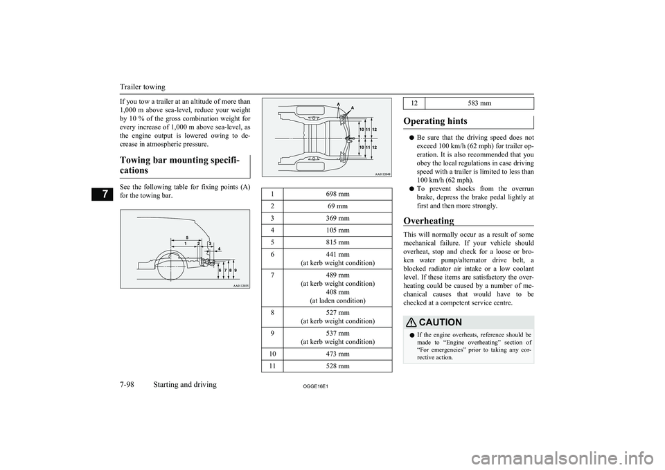
Towing bar mounting specifi- cations
See the following table for fixing points (A) for the towing bar.
1698 mm269 mm3369 mm4105 mm5815 mm6441 mm
(at kerb weight condition)7489 mm
(at kerb weight condition) 408 mm
(at laden condition)8527 mm
(at kerb weight condition)9537 mm
(at kerb weight condition)10473 mm11528 mm12583 mm
Operating hints
l Be sure that the driving speed does not
exceed 100 km/h (62 mph) for trailer op-
eration. It is also recommended that you obey the local regulations in case driving speed with a trailer is limited to less than
100 km/h (62 mph).
l To prevent shocks from the overrun
brake, depress the brake pedal lightly at first and then more strongly.
Overheating
This will normally occur as a result of some
mechanical failure. If your vehicle should overheat, stop and check for a loose or bro-ken water pump/alternator drive belt, a
blocked radiator air intake or a low coolant level. If these items are satisfactory the over-
heating could be caused by a number of me-
chanical causes that would have to be
checked at a competent service centre.
CAUTIONl If the engine overheats, reference should be
made to “Engine overheating” section of
“For emergencies” prior to taking any cor- rective action.
Trailer towing
7-98OGGE16E1Starting and driving7
Page 299 of 490
Parking
It is not recommended to park on a steep
slope while towing trailer.
If parking on a steep slope cannot be avoided,
the road grade should be less than 12% and
the following procedure performed. 1. Apply the parking brake firmly on the
vehicle and the trailer (if fitted).
2. Put the select position in “P”.
3. Place chocks or blocks at the tyres on
both vehicle and trailer.
4. Turn the front wheels into the shoulder
of the road to prevent the vehicle frommoving.
Driving on long up hills while towing trailer
When the remaining quantity of the drive bat-
tery is low, or high-speed driving on long up hills at high temperature, the drive battery
output is restricted and the vehicle speed may
be decreased.
The vehicle speed may be recovered if the drive battery quantity is recovered.
NOTEl In charge mode, if the remaining quantity of
the drive battery can be increased in ad-
vance, it can prevent the vehicle speed from
decreasing on long up hills.
Refer to “Battery charge switch” on page 7-22.
Trailer towing
7-99OGGE16E1Starting and driving7
Page 300 of 490
OGGE16E1