steering wheel MITSUBISHI OUTLANDER PHEV 2018 (in English) User Guide
[x] Cancel search | Manufacturer: MITSUBISHI, Model Year: 2018, Model line: OUTLANDER PHEV, Model: MITSUBISHI OUTLANDER PHEV 2018Pages: 538, PDF Size: 25.01 MB
Page 140 of 538
The front airbags and driver’s
knee airbag MAY DEPLOY when…
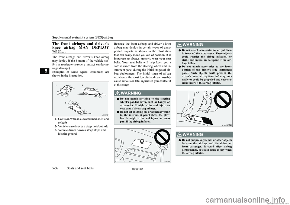
The front airbags and driver’s knee airbagmay deploy if the bottom of the vehicle suf-
fers a moderate-to-severe impact (undercar- riage damage).
Examples of some typical conditions are shown in the illustration.
1- Collision with an elevated median/island or kerb
2- Vehicle travels over a deep hole/pothole
3- Vehicle drives down a steep slope and hits the ground
Because the front airbags and driver’s knee
airbag may deploy in certain types of unex- pected impacts as shown in the illustration that can easily move you out of position, it is important to always properly wear your seat belts. Your seat belts will help keep you a
safe distance from the steering wheel and in- strument panel during the initial stages of air-
bag deployment. The initial stage of airbag inflation is the most forceful and can possibly
cause serious or fatal injuries if you contact it
at this stage.WARNINGl Do not attach anything to the steering
wheel’s padded cover, such as badges or accessories. It might strike and injure an
occupant if the airbag inflates.
l Do not set anything on, or attach anything
to, the instrument panel above the glove box. It might strike and injure an occu- pant if the airbag inflates.WARNINGl Do not attach accessories to, or put them
in front of, the windscreen. These objects
could restrict the airbag inflation, or strike and injure an occupant if the air-
bags inflate.
l Do not attach accessories to the lower
portion of the driver’s side instrumentpanel. Such objects could prevent the
driver’s knee airbag from inflating nor-
mally or could be propelled and cause se- rious injury if the airbag inflates.WARNINGl Do not put packages, pets or other objects
between the airbags and the driver orfront passenger. It could affect airbagperformance, or could cause injury when the airbag inflates.
Supplemental restraint system (SRS)-airbag
5-32OGGE18E1Seats and seat belts5
Page 144 of 538
SRS warning lamp/display
E00407803191
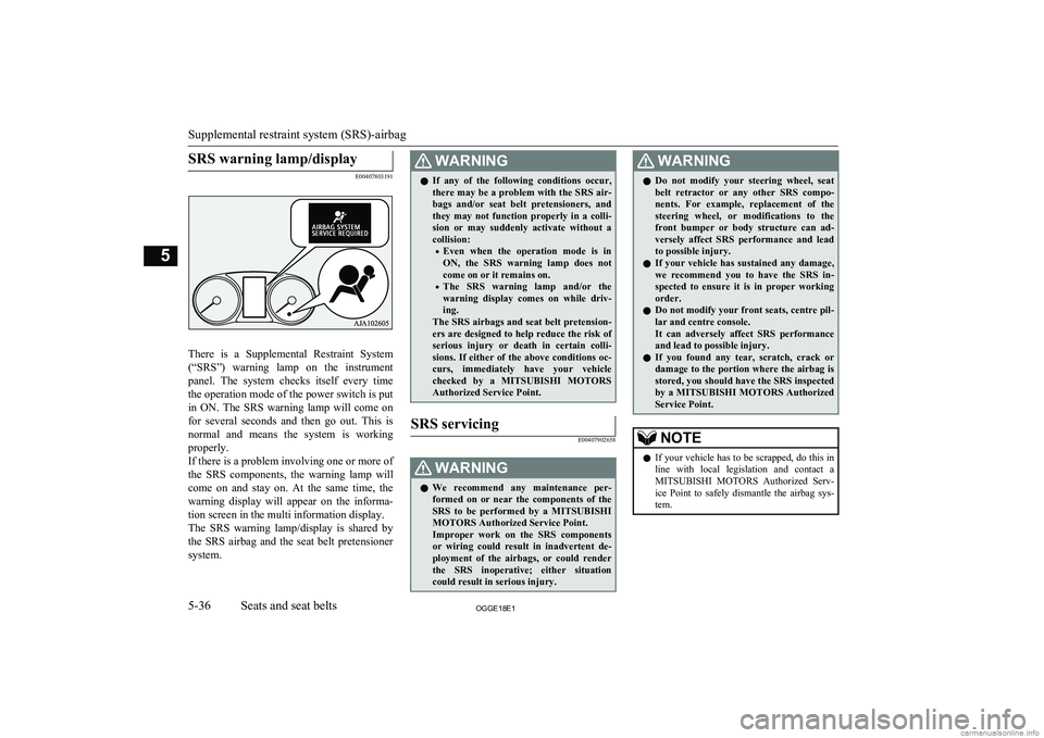
There is a Supplemental Restraint System(“SRS”) warning lamp on the instrument panel. The system checks itself every time
the operation mode of the power switch is put in ON. The SRS warning lamp will come on
for several seconds and then go out. This is
normal and means the system is working
properly.
If there is a problem involving one or more of
the SRS components, the warning lamp will come on and stay on. At the same time, thewarning display will appear on the informa-
tion screen in the multi information display.
The SRS warning lamp/display is shared by
the SRS airbag and the seat belt pretensioner system.
WARNINGl If any of the following conditions occur,
there may be a problem with the SRS air- bags and/or seat belt pretensioners, and they may not function properly in a colli-
sion or may suddenly activate without a
collision:
• Even when the operation mode is in
ON, the SRS warning lamp does not come on or it remains on.
• The SRS warning lamp and/or the
warning display comes on while driv- ing.
The SRS airbags and seat belt pretension- ers are designed to help reduce the risk of
serious injury or death in certain colli- sions. If either of the above conditions oc-
curs, immediately have your vehicle checked by a MITSUBISHI MOTORS
Authorized Service Point.SRS servicing
E00407902658WARNINGl We recommend any maintenance per-
formed on or near the components of the
SRS to be performed by a MITSUBISHI
MOTORS Authorized Service Point.
Improper work on the SRS components
or wiring could result in inadvertent de- ployment of the airbags, or could render
the SRS inoperative; either situation could result in serious injury.WARNINGl Do not modify your steering wheel, seat
belt retractor or any other SRS compo- nents. For example, replacement of the
steering wheel, or modifications to the
front bumper or body structure can ad- versely affect SRS performance and lead
to possible injury.
l If your vehicle has sustained any damage,
we recommend you to have the SRS in- spected to ensure it is in proper workingorder.
l Do not modify your front seats, centre pil-
lar and centre console.
It can adversely affect SRS performance and lead to possible injury.
l If you found any tear, scratch, crack or
damage to the portion where the airbag is stored, you should have the SRS inspected
by a MITSUBISHI MOTORS Authorized
Service Point.NOTEl If your vehicle has to be scrapped, do this in
line with local legislation and contact a
MITSUBISHI MOTORS Authorized Serv-
ice Point to safely dismantle the airbag sys- tem.
Supplemental restraint system (SRS)-airbag
5-36OGGE18E1Seats and seat belts5
Page 145 of 538
Instruments.......................................................................................... 6-02
Multi information display................................................................... 6-02
Indication lamp, warning lamp, and information screen display list....................................................................................... 6-21
Indication lamps.................................................................................. 6-47
Warning lamps.................................................................................... 6-48
Information screen display.................................................................. 6-51
Combination headlamps and dipper switch........................................ 6-52
Headlamp levelling............................................................................. 6-59
Turn-signal lever................................................................................. 6-60
Hazard warning flasher switch............................................................6-60 ECO mode switch............................................................................... 6-61
Fog lamp switch.................................................................................. 6-61
Wiper and washer switch.................................................................... 6-62
Wiper de-icer switch*......................................................................... 6-67
Rear window demister switch............................................................. 6-67
Heated windscreen switch*.................................................................6-68 Heated steering wheel switch*............................................................6-69Horn switch......................................................................................... 6-70Instruments and controls
OGGE18E16
Page 213 of 538
CAUTIONlWhile heated windscreen is operating, the
outer surface of the windscreen will be hot.
Do not touch the windscreen to prevent
burns.NOTEl Remove snow before use of the heated
windscreen. It is not possible to melt largeamount of accumulated snow by the heated windscreen.
l To avoid the battery runs out, do not use the
heated windscreen continuously.Heated steering wheel
switch* E00532100042
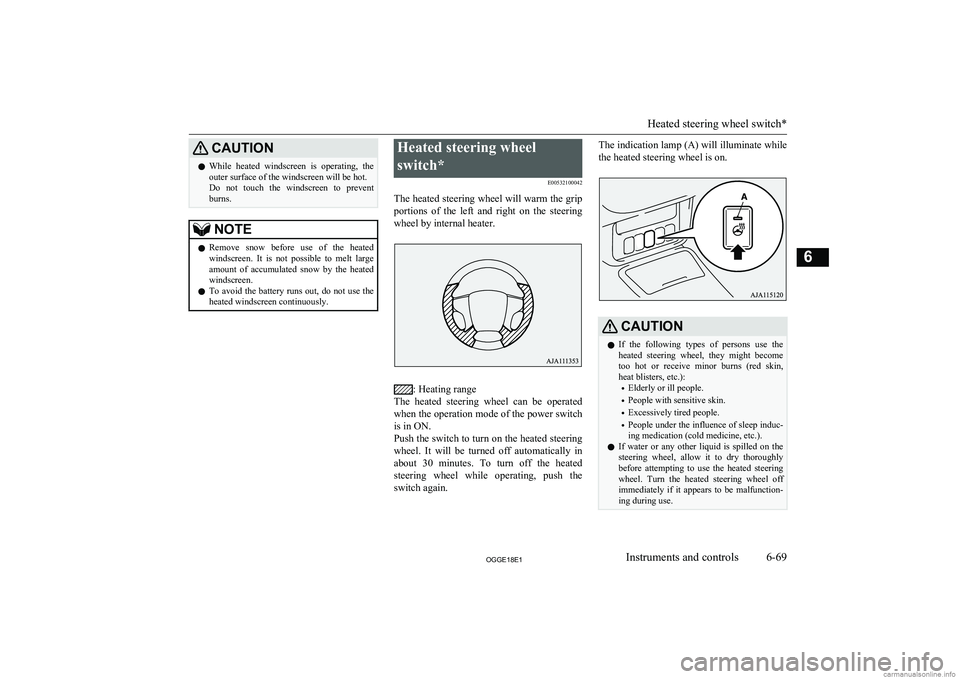
The heated steering wheel will warm the grip portions of the left and right on the steering
wheel by internal heater.
: Heating range
The heated steering wheel can be operated
when the operation mode of the power switch
is in ON.
Push the switch to turn on the heated steering
wheel. It will be turned off automatically in about 30 minutes. To turn off the heated
steering wheel while operating, push the
switch again.
The indication lamp (A) will illuminate while
the heated steering wheel is on.CAUTIONl If the following types of persons use the
heated steering wheel, they might become too hot or receive minor burns (red skin,
heat blisters, etc.):
• Elderly or ill people.
• People with sensitive skin.
• Excessively tired people.
• People under the influence of sleep induc-
ing medication (cold medicine, etc.).
l If water or any other liquid is spilled on the
steering wheel, allow it to dry thoroughly
before attempting to use the heated steering
wheel. Turn the heated steering wheel off
immediately if it appears to be malfunction- ing during use.
Heated steering wheel switch*
6-69OGGE18E1Instruments and controls6
Page 214 of 538
CAUTIONlLong use of the heated steering wheel when
the ready indicator is not illuminated may run down the auxiliary battery.Horn switch
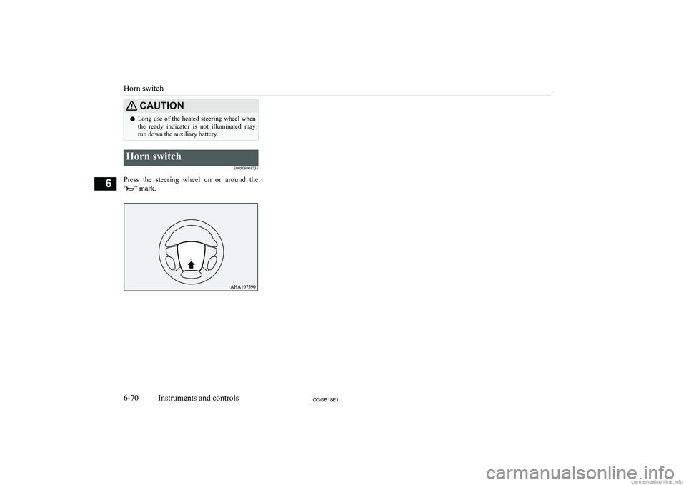
E00508001735
Press the steering wheel on or around the
“
” mark.
Horn switch
6-70OGGE18E1Instruments and controls6
Page 215 of 538
Economical driving............................................................................. 7-02
Driving, alcohol and drugs.................................................................. 7-02
Safe driving techniques....................................................................... 7-02
Parking brake...................................................................................... 7-03 Parking................................................................................................ 7-06
Steering wheel height and reach adjustment....................................... 7-07
Inside rear-view mirror....................................................................... 7-07
Outside rear-view mirrors................................................................... 7-09
Power switch....................................................................................... 7-12 Starting and stopping the Plug-in Hybrid EV System........................ 7-14
Selector lever (Joystick type).............................................................. 7-16 Select position indicator...................................................................... 7-17
Electrical Parking switch.................................................................... 7-18
Regenerative braking level selector (paddle type)*............................ 7-19
S-AWC (Super All Wheel Control).................................................... 7-21
4-wheel drive operation...................................................................... 7-23
Inspection and maintenance following rough road operation............. 7-24
Cautions on handling of 4-wheel drive vehicles................................. 7-24
EV switch............................................................................................ 7-25
Battery save mode switch................................................................... 7-27
Battery charge mode switch................................................................ 7-28 Acoustic Vehicle Alerting System (AVAS)....................................... 7-29
Braking................................................................................................ 7-30
Brake auto hold................................................................................... 7-32
Hill start assist..................................................................................... 7-34
Brake assist system............................................................................. 7-35
Emergency stop signal system............................................................ 7-36
Anti-lock brake system (ABS)............................................................ 7-36
Electric power steering system (EPS)................................................. 7-39Active stability control (ASC)............................................................ 7-40
Cruise control*.................................................................................... 7-42
Speed Limiter*.................................................................................... 7-47
Adaptive Cruise Control System (ACC)*...........................................7-52 Forward Collision Mitigation System (FCM)*...................................7-64Ultrasonic misacceleration Mitigation System (UMS)*..................... 7-74Blind Spot Warning (BSW) (with Lane Change Assist)*.................. 7-79
Rear Cross Traffic Alert (RCTA)*..................................................... 7-83Lane Departure Warning (LDW)*...................................................... 7-85
Tyre pressure monitoring system (TPMS).......................................... 7-89 Reversing sensor system*................................................................... 7-94
Parking sensors (Front/Rear)*............................................................ 7-98
Rear-view camera*........................................................................... 7-102 Multi Around Monitor*.................................................................... 7-106
Cargo loads....................................................................................... 7-115 Trailer towing....................................................................................7-116Starting and driving
OGGE18E17
Page 221 of 538
WARNINGlLeaving the engine running risks injury
or death from accidentally moving the se-
lector lever or the accumulation of toxic
exhaust fumes on the passenger compart- ment.
Where you park
WARNINGl Do not park your vehicle in areas where
combustible materials such as dry grass
or leaves can come in contact with a hot exhaust, since a fire could occur.
When leaving the vehicle
Always carry the key and lock all doors and
the tailgate when leaving the vehicle unatten-
ded.
Always try to park your vehicle in a well lit
area.
CAUTIONl When you leave the vehicle, be sure that you
have stopped the Plug-in Hybrid EV System.
The engine may start suddenly by a remain-
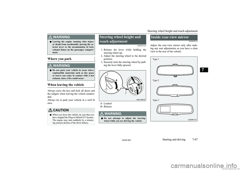
ing amount decline of the drive battery.Steering wheel height and
reach adjustment E00600701652
1. Release the lever while holding the
steering wheel up.
2. Adjust the steering wheel to the desired
position.
3. Securely lock the steering wheel by pull-
ing the lever fully upward.
A- Locked B- Release
WARNINGl Do not attempt to adjust the steering
wheel while you are driving the vehicle.Inside rear-view mirror
E00600802168
Adjust the rear-view mirror only after mak-
ing any seat adjustments so you have a clear
view to the rear of the vehicle.
Steering wheel height and reach adjustment
7-07OGGE18E1Starting and driving7 Type 1
Type 2
Type 3
Page 229 of 538
Stopping the Plug-in HybridEV System
E00620801457
1. Stop your vehicle completely.
2. Apply the parking brake firmly while
depressing the brake pedal.
3. After pressing the electrical parking
switch, press the power switch to stop the Plug-in Hybrid EV System. (Refer to“Electrical Parking switch” on page
7-18.)
WARNINGl Never stop the Plug-in Hybrid EV System
during running except in an emergency. The effectiveness of the brake becomes
very poor and the steering wheel becomes very heavy, which can easily lead to an ac-
cident.NOTEl Do not operate the power switch during run-
ning except in an emergency. If you have to stop the Plug-in Hybrid EV System becauseof an emergency during operation, continue to press the power switch for three seconds
or longer or press the power switch three times or more quickly. The Plug-in Hybrid
EV System stops, the operation mode turns to ACC, and the selector lever position shifts
to the “P” position at very slow speed.NOTEl If you press the power switch when the se-
lector lever position is other than the “P” po-
sition while your vehicle is stopped, the se- lector lever position automatically shifts to
the “P” position, Plug-in Hybrid EV System stops, and the power mode turns to “OFF”.
l If the parking lock mechanism is faulty, a
warning is displayed on the information
screen in the multi-information display. When this warning is displayed, the Plug-in
Hybrid EV System cannot be stopped unless
you apply the parking brake and then press the power switch. Park on a flat place with
the parking brake securely applied. Have your vehicle inspected by a MITSUBISHI
MOTORS Authorized Service Point.If the keyless operation key is
not operating properly
E00632901237
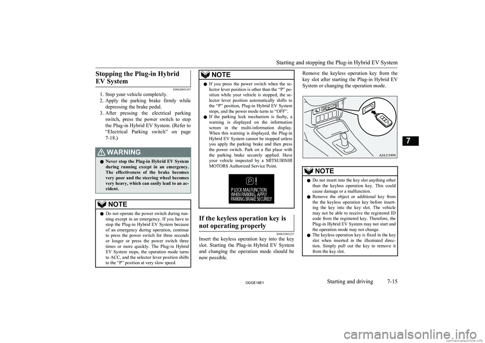
Insert the keyless operation key into the key
slot. Starting the Plug-in Hybrid EV System and changing the operation mode should be now possible.
Remove the keyless operation key from the
key slot after starting the Plug-in Hybrid EV
System or changing the operation mode.NOTEl Do not insert into the key slot anything other
than the keyless operation key. This couldcause damage or a malfunction.
l Remove the object or additional key from
the the keyless operation key before insert-ing the key into the key slot. The vehicle
may not be able to receive the registered ID
code from the registered key. Therefore, the Plug-in Hybrid EV System may not start and
the operation mode may not change.
l The keyless operation key is fixed in the key
slot when inserted in the illustrated direc- tion. Simply pull out the key to remove it
from the key slot.
Starting and stopping the Plug-in Hybrid EV System
7-15OGGE18E1Starting and driving7
Page 233 of 538
CAUTIONlIf you operate the electrical parking switch
and the select lever repeatedly within a short
time, the shifting from the “P” position or to the “P” position is restrained for a certainperiod for the system protection. In such a
case, wait for a while and then perform the operation.
l If the parking lock mechanism is faulty, a
warning is displayed on the information
screen in the multi-information display.
When this warning is displayed, park on a flat place with the parking brake securely
applied. Have your vehicle inspected by a MITSUBISHI MOTORS Authorized Serv-
ice Point.
l If you press the electrical parking switch be-
fore your vehicle stops completely, the vehi- cle makes a sudden stop, which may cause
injury to passengers. This also can be a cause of failure of the vehicle.
l Do not place an object around the electrical
parking switch. The electrical parking switch
may be pressed by the object when you
place it there or when you somehow touch it. This will cause unintentional shifting to “P” or “N” position, which may lead to an acci-
dent.
CAUTIONl Be careful not to spill beverages, etc. around
the electrical parking switch. The electrical
parking switch may be stuck to the pressed
position when it is pressed.NOTEl When the selector lever is shifted from the
“P” position or to the “P” position, operatingnoise and vibration of the parking lock are felt, but this is normal.
Electrical Parking switch re-
minder buzzer
If the driver’s door is opened with the select
position other than “P” when the vehicle is at a stop, the buzzer sounds to warn to press the
electrical parking switch.
Regenerative braking level
selector (paddle type)* E00636700119
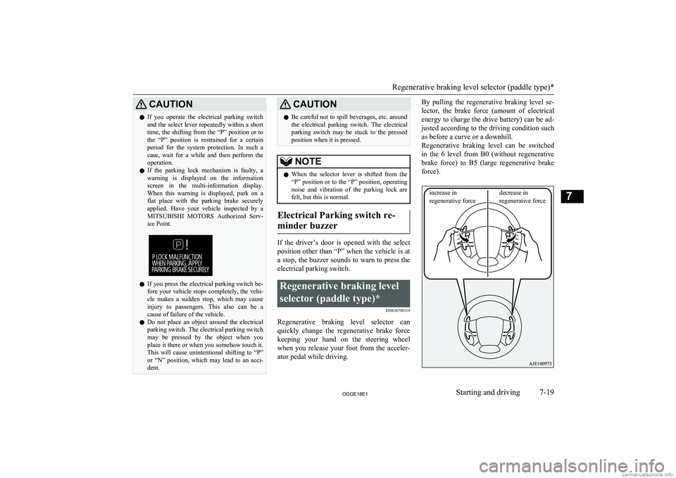
Regenerative braking level selector canquickly change the regenerative brake force
keeping your hand on the steering wheel when you release your foot from the acceler-
ator pedal while driving.
By pulling the regenerative braking level se-
lector, the brake force (amount of electrical energy to charge the drive battery) can be ad- justed according to the driving condition such
as before a curve or a downhill.
Regenerative braking level can be switched in the 6 level from B0 (without regenerativebrake force) to B5 (large regenerative brake
force).
Regenerative braking level selector (paddle type)*
7-19OGGE18E1Starting and driving7 increase in
regenerative forcedecrease in
regenerative force
Page 235 of 538
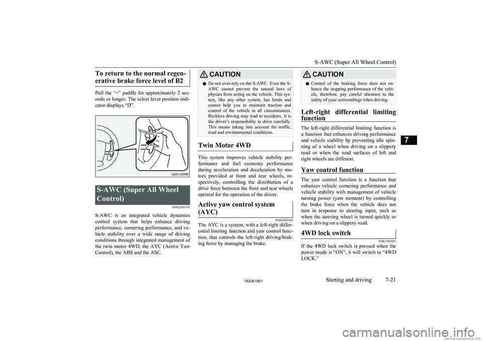
To return to the normal regen-erative brake force level of B2
Pull the “+” paddle for approximately 2 sec-
onds or longer. The select lever position indi-
cator displays “D”.
S-AWC (Super All Wheel
Control) E00622601185
S-AWC is an integrated vehicle dynamics
control system that helps enhance driving
performance, cornering performance, and ve-
hicle stability over a wide range of driving conditions through integrated management of the twin motor 4WD, the AYC (Active Yaw
Control), the ABS and the ASC.
CAUTIONl Do not over-rely on the S-AWC. Even the S-
AWC cannot prevent the natural laws of
physics from acting on the vehicle. This sys- tem, like any other system, has limits and
cannot help you to maintain traction and
control of the vehicle in all circumstances. Reckless driving may lead to accidents. It is the driver’s responsibility to drive carefully.
This means taking into account the traffic,
road and environmental conditions.
Twin Motor 4WD
This system improves vehicle stability per-
formance and fuel economy performanceduring acceleration and deceleration by mo-
tors provided at front and rear wheels, re- spectively, controlling the distribution of a
drive force between the front and rear wheels optimal for the operation of the driver.
Active yaw control system
(AYC)
E00622801044
The AYC is a system, with a left-right differ- ential limiting function and yaw control func-
tion, that controls the left-right driving/brak-
ing force by managing the brake.
CAUTIONl Control of the braking force does not en-
hance the stopping performance of the vehi-
cle, therefore, pay careful attention to the safety of your surroundings when driving.
Left-right differential limiting
function
The left-right differential limiting function is
a function that enhances driving performance and vehicle stability by preventing idle spin-
ning of a wheel when driving on a slippery road or when the road surfaces of left andright wheels are different.
Yaw control function
The yaw control function is a function thatenhances vehicle cornering performance and vehicle stability with management of vehicle
turning power (yaw moment) by controlling the brake force when the vehicle does not
turn in response to steering input, such as
when the steering wheel is turned quickly or when driving on a slippery road.
4WD lock switch
E00637000063
If the 4WD lock switch is pressed when the
power mode is “ON”, it will switch to “4WD LOCK.”
S-AWC (Super All Wheel Control)
7-21OGGE18E1Starting and driving7