steering wheel MITSUBISHI OUTLANDER PHEV 2018 (in English) Owner's Guide
[x] Cancel search | Manufacturer: MITSUBISHI, Model Year: 2018, Model line: OUTLANDER PHEV, Model: MITSUBISHI OUTLANDER PHEV 2018Pages: 538, PDF Size: 25.01 MB
Page 324 of 538
NOTElIf there is no operation for 3 minutes after
the Multi Around Monitor is displayed by pressing the switch with the select position
in a position other than “R”, the display dis- appears.Switching of the screen (Select
position is “R”)
E00652900076
If the switch is pressed, the mode of Multi Around Monitor is switched as follows.
Screen of the inside rear-view mirror
Bird’s eye-view/Rear-view mode Side-
view/ Rear-view mode
OFF
Screen of the DISPLAY AUDIO, the
Smartphone Link Display Audio or the
MITSUBISHI Multi-Communication Sys-
tem (MMCS)
Bird’s eye-view/Rear-view mode
Side-
view/ Rear-view mode
Switching of the screen (Select
position is other than “R”)
E00652900089
If the switch is pressed, the mode of Multi Around Monitor is switched, Bird’s eyeview/ Front-view mode
Side-view/Frontview
mode
OFF
NOTEl When you put the select position to the “R”
(REVERSE) position with the front-viewdisplayed on the driver’s side screen, the
driver’s side screen switches to the rear-view
mode. When you put the select position to any other position, the driver’s side screen
switches to the front-view mode.
l When the switch is pressed at the vehicle
speed of approximately 10 km/h (6 mph) or
higher, only the side-view can be displayed on the passenger’s side screen.
l The front-view will not be displayed when
the vehicle speed exceeds approximately
10 km/h (6 mph).
l The display of the view may be delayed dur-
ing switching of the screen.How to read the screen
E00645400079
In any mode other than the Bird’s eye-view
mode, the lines in the screen give the follow-
ing information. Use them only as a guide.
CAUTIONl When you accidentally hit the camera and its
circumference against something, the view and the lines in the screen may not be dis-played correctly. Be sure to have it inspected
by a MITSUBISHI MOTORS Authorized
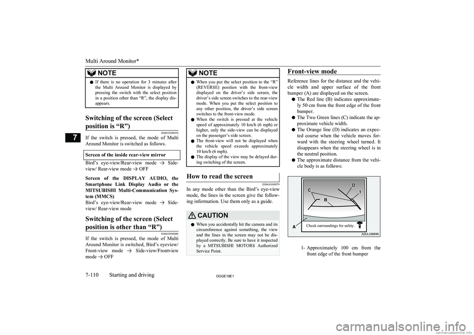
Service Point.Front-view mode
Reference lines for the distance and the vehi-
cle width and upper surface of the front bumper (A) are displayed on the screen.
l The Red line (B) indicates approximate-
ly 50 cm from the front edge of the front
bumper.
l The Two Green lines (C) indicate the ap-
proximate vehicle width.
l The Orange line (D) indicates an expec-
ted course when the vehicle moves for-
ward with the steering wheel turned. It disappears when the steering wheel is in
the neutral position.
l The approximate distance from the vehi-
cle body is as follows:
1- Approximately 100 cm from the
front edge of the front bumper
Multi Around Monitor*
7-110OGGE18E1Starting and driving7 Check surroundings for safety.
Page 325 of 538
NOTElWhen the expected course lines are dis-
played in the front-view, the expected course lines are also displayed in the bird’s eyeview(Front: solid line, Rear: broken line).Rear-view mode
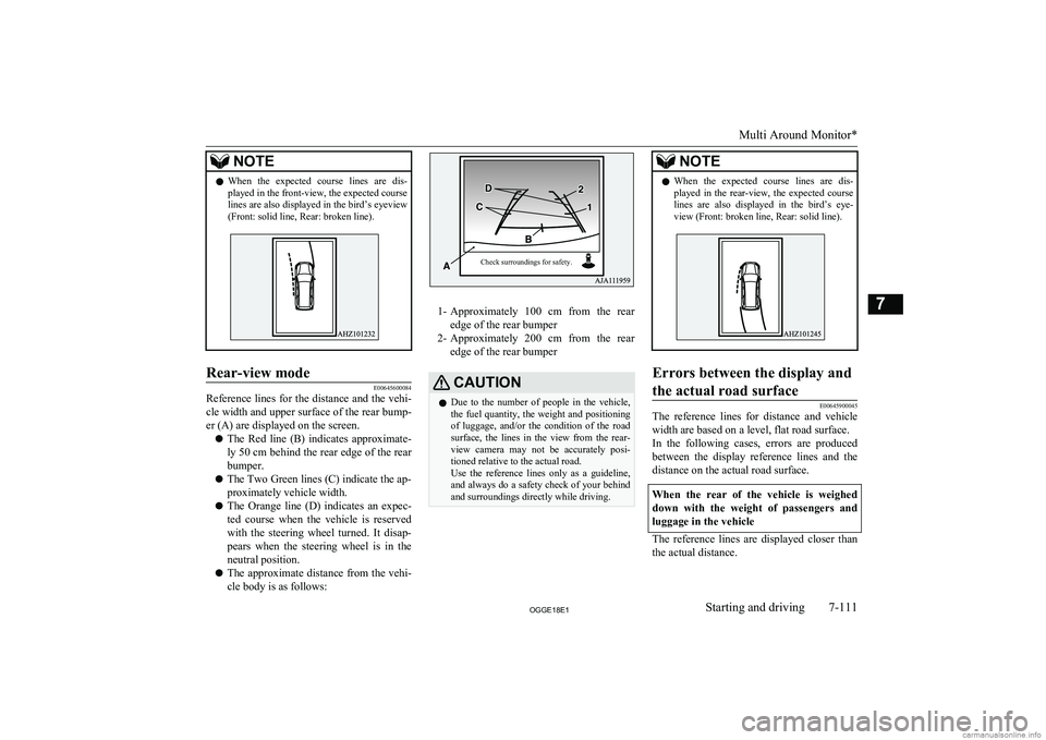
E00645600084
Reference lines for the distance and the vehi-
cle width and upper surface of the rear bump-
er (A) are displayed on the screen.
l The Red line (B) indicates approximate-
ly 50 cm behind the rear edge of the rear
bumper.
l The Two Green lines (C) indicate the ap-
proximately vehicle width.
l The Orange line (D) indicates an expec-
ted course when the vehicle is reserved
with the steering wheel turned. It disap- pears when the steering wheel is in the
neutral position.
l The approximate distance from the vehi-
cle body is as follows:
1- Approximately 100 cm from the rear
edge of the rear bumper
2- Approximately 200 cm from the rear
edge of the rear bumper
CAUTIONl Due to the number of people in the vehicle,
the fuel quantity, the weight and positioning of luggage, and/or the condition of the roadsurface, the lines in the view from the rear-
view camera may not be accurately posi- tioned relative to the actual road.
Use the reference lines only as a guideline,
and always do a safety check of your behind and surroundings directly while driving.NOTEl When the expected course lines are dis-
played in the rear-view, the expected course lines are also displayed in the bird’s eye-view (Front: broken line, Rear: solid line).Errors between the display and
the actual road surface
E00645900045
The reference lines for distance and vehicle width are based on a level, flat road surface.In the following cases, errors are produced between the display reference lines and the
distance on the actual road surface.
When the rear of the vehicle is weighed down with the weight of passengers and
luggage in the vehicle
The reference lines are displayed closer than the actual distance.
Multi Around Monitor*
7-111OGGE18E1Starting and driving7 Check surroundings for safety.
Page 358 of 538
15- key/ key
For audio, select audio track/file; for ra-
dio, perform automatic station selection
or ensemble/service station selection.16- MENU key Switch to Menu mode.17-/SEL key
Adjust audio quality and select items.
For radio, manually select stations.
Steering wheel audio remote
control switches
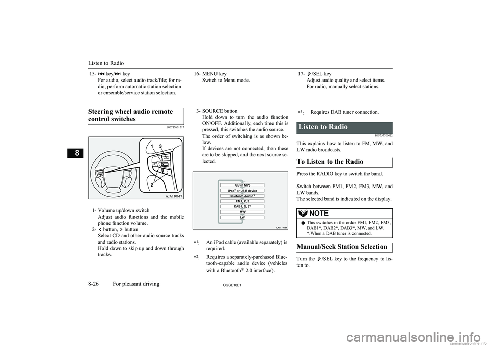
E00737601517
1- Volume up/down switch Adjust audio functions and the mobile
phone function volume.
2-
button, button
Select CD and other audio source tracks
and radio stations.
Hold down to skip up and down through tracks.
3- SOURCE button
Hold down to turn the audio functionON/OFF. Additionally, each time this is
pressed, this switches the audio source.
The order of switching is as shown be- low.
If devices are not connected, then these are to be skipped, and the next source se-lected.CD or MP3MWLWDAB1, 2, 3 *3FM1, 2, 3Bluetooth Audio *2iPod*1
or USB device*1
:An iPod cable (available separately) is
required.* 2
:Requires a separately-purchased Blue-
tooth-capable audio device (vehicles
with a Bluetooth ®
2.0 interface).*3
:Requires DAB tuner connection.Listen to Radio
E00737700032
This explains how to listen to FM, MW, and
LW radio broadcasts.
To Listen to the Radio
Press the RADIO key to switch the band.
Switch between FM1, FM2, FM3, MW, and LW bands.
The selected band is indicated on the display.
NOTEl This switches in the order FM1, FM2, FM3,
DAB1*, DAB2*, DAB3*, MW, and LW. *:When a DAB tuner is connected.
Manual/Seek Station Selection
Turn the /SEL key to the frequency to lis-
ten to.
Listen to Radio
8-26OGGE18E1For pleasant driving8
Page 394 of 538
5.If only one telephone number is regis-
tered under the name you just said, the
voice guide proceeds to Step 6.
If two or more telephone numbers are registered that match the name you just
said, the voice guide will say “Would you like to call
location to call.NOTEl If the name you selected has matching data
in the vehicle phone book but no telephone
number is registered under the selected loca- tion, the voice guide will say “{home/work/
mobile/other} not found for
Say “Add location” and you can register an
additional telephone number under the selec-
ted location.
l If the name you selected has matching data
in the mobile phone book but no telephone
number is registered under the selected loca- tion, the voice guide will say “{home/work/
mobile/other} not found for
Answer “Yes,” and the system will return to Step 3.
Answer “No,” and the call will be cancelled. Start over again from Step 1.6. The voice guide will say “Calling
tem will dial the telephone number.NOTEl When the confirmation function is on, the
system will ask if the name and location of the receiver are correct. If the name is cor-
rect, answer “Yes.”
To change the name or location to call, an- swer “No.” The system will return to Step 3.
Redialing
You can redial the last number called, based
on the history of dialed calls in the paired cel-
lular phone.
Use the following procedure to redial. 1. Press the SPEECH button.
2. Say “Redial.”
SEND function
E00761300035
During a call, press the SPEECH button to
enter voice recognition mode, then say “
For example, if during a call you need to sim- ulate the press of a phone button as a re-
sponse to an automated system, press the SPEECH button and speak “1 2 3 4 pound SEND” and the 1234# will be sent on your
cellular phone.
Receiving calls
E00761601064
If an incoming phone call is received while
the operation mode is in ON or ACC, the au-dio system will be automatically turned on
and switched to the incoming call, even when the audio system was originally off.
The voice guide announcement for the in- coming call will be output from the front pas- senger’s seat speaker.
If the CD player or radio was playing when
the incoming call was received, the audio
system will mute the sound from the CD player or radio and output only the incomingcall.
To receive the call, press the PICK-UP but- ton on the steering wheel control switch.
When the call is over, the audio system will
return to its previous state.
MUTE function
E00760300041
At any time during a call, you can mute the vehicle microphone.
Pressing the SPEECH button and then saying
“Mute” during a call will turn ON the MUTE
function and mute the microphone.
Saying “Mute off” in the same way will turn off the MUTE function and cancel the muteon the microphone.
Bluetooth ®
2.0 interface*
8-62OGGE18E1For pleasant driving8
Page 420 of 538
If the vehicle breaks downE00800102408
If the vehicle breaks down on the road, move it to the shoulder and use the hazard warning
flashers and/or the warning triangle etc.
Refer to “Hazard warning flasher switch” on page 6-60.
If you need to push your vehicle, put the op-
eration mode of the power switch in ON and put the select position in “N” (NEUTRAL) position.WARNINGl If you are unable to safely assess the vehi-
cle due to vehicle damage, do not touch
the vehicle. Leave the vehicle and contact emergency services. Advise emergency
responders that this is a Plug-in Hybrid Electric vehicle.
If the ready indicator goes out
while driving
Vehicle operation and control are affected if
the ready indicator goes out while driving.
Before moving the vehicle to a safe area, be aware of the following:
l The brake booster may becomes inoper-
ative and the pedal effort will increase.
Press down the brake pedal harder than usual.
l The power steering system may not op-
erate, the steering wheel feels heavy when turning it.Emergency starting
E00800504204
If the Plug-in Hybrid EV system cannot be
started because the auxiliary battery is weak or dead, the battery from another vehicle can
be used with jumper cables to start the Plug-
in Hybrid EV system.
WARNINGl To start the Plug-in Hybrid EV system us-
ing jumper cables from another vehicle
and perform the correct procedures ac-
cording to the instruction below. Incor-
rect procedures could result in a fire, ex- plosion, electric shock or damage to the
vehicles.
l Keep sparks, cigarettes and flames away
from the battery because the battery may
produce an explosion.CAUTIONl The Plug-in Hybrid EV system cannot be
started by pulling or pushing the vehicle.
l Check the other vehicle. It must have a 12-
volt battery. If the other system isn’t 12-volt, shorting can damage both vehicles.
l Use the proper cables suitable for the battery
size to prevent overheating of the cables.CAUTIONl Check the jumper cables for damage and
corrosion before use.
l Always wear protective eye goggles when
working near the battery.
l Keep the battery out of the reach of children.
l Do not attempt jump starting the auxiliary
battery while the drive battery is being charged. Doing so could damage the charg-
ing equipment or the vehicle.NOTEl If the auxiliary battery is disconnected, the
operation mode of the power switch is mem-
orized. When a booster battery is connected
by jumper cables, the operation mode re- turns to the state it had before the auxiliary
battery ran down.
Pay due attention if you do not know the op- eration mode before the auxiliary battery
was fully discharged.
l If the auxiliary battery is fully discharged
with the select position in the “P” (PARK)
position, the select position cannot be changed to other position from the “P”
(PARK) position in some cases. In such a case, the front wheels have been locked.
Therefore, the vehicle cannot be moved.
1. Get the vehicles close enough so the
jumper cables can reach, but be sure the vehicles aren’t touching each other.
If the vehicle breaks down
9-02OGGE18E1For emergencies9
Page 430 of 538
NOTElSimply putting sealant and air into the tyre
using the tyre repair kit does not seal the
puncture hole. Air will leak through the puncture hole until the emergency repair procedure is completed (through step 19 or
step 20 of these instructions).
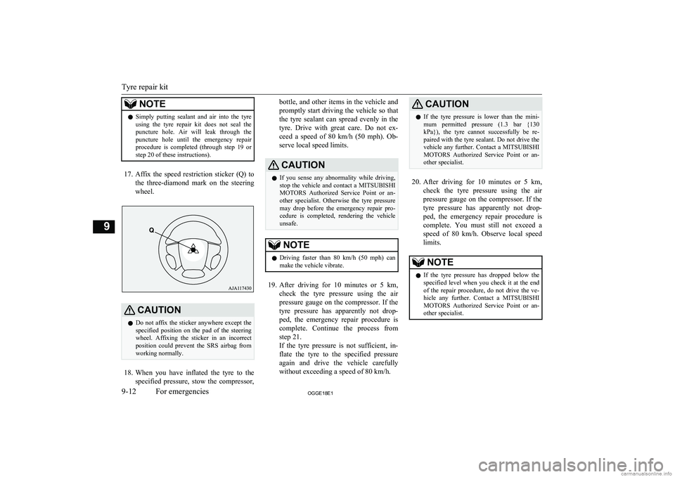
17. Affix the speed restriction sticker (Q) to
the three-diamond mark on the steering wheel.
CAUTIONl Do not affix the sticker anywhere except the
specified position on the pad of the steeringwheel. Affixing the sticker in an incorrect
position could prevent the SRS airbag from working normally.
18. When you have inflated the tyre to the
specified pressure, stow the compressor,
bottle, and other items in the vehicle and
promptly start driving the vehicle so that the tyre sealant can spread evenly in the
tyre. Drive with great care. Do not ex- ceed a speed of 80 km/h (50 mph). Ob-
serve local speed limits.CAUTIONl If you sense any abnormality while driving,
stop the vehicle and contact a MITSUBISHI
MOTORS Authorized Service Point or an-
other specialist. Otherwise the tyre pressure
may drop before the emergency repair pro- cedure is completed, rendering the vehicle
unsafe.NOTEl Driving faster than 80 km/h (50 mph)
can
make the vehicle vibrate.
19. After driving for 10 minutes or 5 km ,
check the tyre pressure using the air
pressure gauge on the compressor. If the
tyre pressure has apparently not drop- ped, the emergency repair procedure iscomplete. Continue the process from
step 21.
If the tyre pressure is not sufficient, in- flate the tyre to the specified pressure
again and drive the vehicle carefully
without exceeding a speed of 80 km/h.
CAUTIONl If the tyre pressure is lower than the mini-
mum permitted pressure (1.3 bar {130 kPa}), the tyre cannot successfully be re-
paired with the tyre sealant. Do not drive the vehicle any further. Contact a MITSUBISHI
MOTORS Authorized Service Point or an-
other specialist.
20. After driving for 10 minutes or 5 km ,
check the tyre pressure using the air
pressure gauge on the compressor. If the
tyre pressure has apparently not drop- ped, the emergency repair procedure iscomplete. You must still not exceed a speed of 80 km/h. Observe local speed
limits.
NOTEl If the tyre pressure has dropped below the
specified level when you check it at the end
of the repair procedure, do not drive the ve- hicle any further. Contact a MITSUBISHI
MOTORS Authorized Service Point or an-
other specialist.
Tyre repair kit
9-12OGGE18E1For emergencies9
Page 435 of 538
CAUTIONlAfter changing the tyre and driving the vehi-
cle about 1,000 km (620 miles), retighten the
wheel nuts to make sure that they have not come loose.
l If the steering wheel vibrates when driving
after changing the tyre, we recommend you to have the tyres checked for balance.
l Do not mix one type of tyre with another or
use a different size from the one listed. This
would cause early wear and poor handling.To store the tools and jack
E00803800037
Reverse the removing procedure when stor-
ing the jack, jack bar and wheel nut wrench.
Refer to “Tools and jack” on page 9-06.
Towing
E00801504953
If your vehicle needs to be tow-
ed
If you need to tow your vehicle, we recom- mend that you contact a MITSUBISHI
MOTORS Authorized Service Point or a
commercial tow truck service.
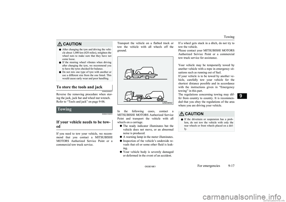
Transport the vehicle on a flatbed truck or
tow the vehicle with all wheels off the
ground.
In the following cases, contact a MITSUBISHI MOTORS Authorized Service
Point and transport the vehicle with all wheels on a carriage.
l The ready indicator illuminates but the
vehicle does not move, or an abnormal
noise is produced.
l A warning lamp in the meter illuminates.
l Inspection of the vehicle’s underside re-
veals that oil or some other fluid is leak- ing.
l Your vehicle body is severely damaged
or deformed in the event of an accident.
If a wheel gets stuck in a ditch, do not try to
tow the vehicle.
Please contact your MITSUBISHI MOTORS
Authorized Service Point or a commercial tow truck service for assistance.
Your vehicle may be temporarily towed by
another vehicle with a rope in emergency sit- uations such as running out of fuel.
If your vehicle is to be towed by another ve-
hicle, carefully tow your vehicle for the shortest distance possible and in accordance
with the instructions given in “Emergency
towing” in this part.
The regulations concerning towing may dif-
fer from country to country. It is recommen-
ded that you obey the regulations of the area where you are driving your vehicle.CAUTIONl If the drivetrain or suspension has a prob-
lem, do not tow the vehicle with only the
rear wheels or front wheels placed on a dol- ly.
Towing
9-17OGGE18E1For emergencies9
Page 437 of 538
If your vehicle is to be towed by
another vehicleWARNINGl Never tow your vehicle in this method ex-
cept in emergency situations such as run-
ning out of fuel. If the vehicle is towed in this method, a problem can occur in thevehicle damaging the motor, transaxle,
etc. indicated by illuminating warning lamps.
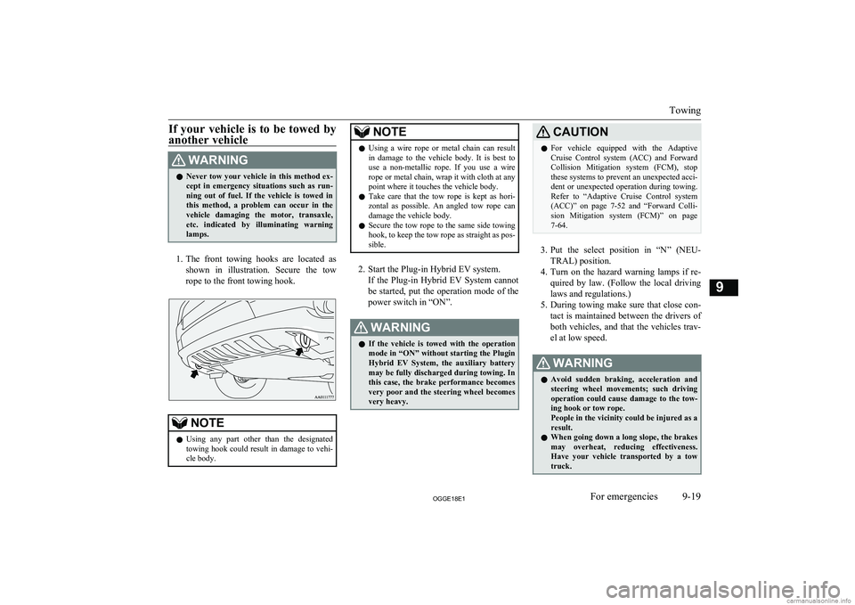
1. The front towing hooks are located as
shown in illustration. Secure the tow rope to the front towing hook.
NOTEl Using any part other than the designated
towing hook could result in damage to vehi-cle body.NOTEl Using a wire rope or metal chain can result
in damage to the vehicle body. It is best to use a non-metallic rope. If you use a wire
rope or metal chain, wrap it with cloth at any
point where it touches the vehicle body.
l Take care that the tow rope is kept as hori-
zontal as possible. An angled tow rope can
damage the vehicle body.
l Secure the tow rope to the same side towing
hook, to keep the tow rope as straight as pos-
sible.
2. Start the Plug-in Hybrid EV system.
If the Plug-in Hybrid EV System cannotbe started, put the operation mode of the
power switch in “ON”.
WARNINGl If the vehicle is towed with the operation
mode in “ON” without starting the Plugin
Hybrid EV System, the auxiliary battery may be fully discharged during towing. In
this case, the brake performance becomes very poor and the steering wheel becomes
very heavy.CAUTIONl For vehicle equipped with the Adaptive
Cruise Control system (ACC) and Forward Collision Mitigation system (FCM), stopthese systems to prevent an unexpected acci-
dent or unexpected operation during towing. Refer to “Adaptive Cruise Control system
(ACC)” on page 7-52 and “Forward Colli-
sion Mitigation system (FCM)” on page 7-64.
3. Put the select position in “N” (NEU-
TRAL) position.
4. Turn on the hazard warning lamps if re-
quired by law. (Follow the local driving
laws and regulations.)
5. During towing make sure that close con-
tact is maintained between the drivers of
both vehicles, and that the vehicles trav-
el at low speed.
WARNINGl Avoid sudden braking, acceleration and
steering wheel movements; such driving
operation could cause damage to the tow- ing hook or tow rope.
People in the vicinity could be injured as a
result.
l When going down a long slope, the brakes
may overheat, reducing effectiveness.
Have your vehicle transported by a tow truck.
Towing
9-19OGGE18E1For emergencies9
Page 439 of 538
WARNINGlWhen trying to rock your vehicle out of a
stuck position, make sure that there are
no people nearby. The rocking motion can make your vehicle suddenly lurch for-
ward or backward, and injure any by- standers.
On a flooded road
l Do not drive on a flooded road. If you
drive on a flooded road, not only does the Plugin Hybrid EV System stop but
there may be a failure like electric leak- age or short circuit.
If you inevitably had to run on a flooded
road and the vehicle was exposed to wa- ter, be sure to have your vehicle inspec-
ted by a MITSUBISHI MOTORS Au-
thorized Service Point.
l If there is water on the brakes after driv-
ing through puddles or washing the vehi- cle, resulting in temporarily ineffective
brakes. In such cases, lightly depress the brake pedal to see if the brakes operate
properly. If they do not, lightly depress the pedal several times while driving in
order to dry the brake pads.
l When driving in rain or on a road with
many puddles a layer of water may form
between the tyres and the road surface.
This reduces a tyre’s frictional resistance
on the road, resulting in loss of steering stability and braking capability.
To cope with this, observe the following
items: A- Drive your vehicle at slow speed.B- Do not drive on worn tyres.
C- Always maintain the specified tyre
inflation pressures.
On a snow-covered or frozen road
l When driving on a snow-covered or fro-
zen road, it is recommended that you use snow tyres or snow traction device (tyre chains).
Refer to the “Snow tyres” and “Snow
traction device (tyre chains)” sections.
l Avoid high-speed operation, sudden ac-
celeration, abrupt brake application and
sharp cornering.
l Depressing the brake pedal during travel
on snowy or icy roads may cause tyre
slippage and skidding. When traction be-
tween the tyres and the road is reduced the wheels may skid and the vehicle can-
not readily be brought to a stop by con- ventional braking techniques. Brakingwill differ, depending upon whether you
have anti-lock brake system (ABS). As your vehicle is equipped with ABS,brake by pressing the brake pedal hard,
and keeping it pressed.
l Allow extra distance between your vehi-
cle and the vehicle in front of you, and avoid sudden braking.
l Accumulation of ice on the braking sys-
tem can cause the wheels to lock. Pullaway from a standstill slowly after con-
firming safety around the vehicle.CAUTIONl Do not press the accelerator pedal rapidly. If
the wheels break free of the ice, the vehicle
could suddenly start moving and possibly cause an accident.
On a bumpy or rutted road
Drive as slow as possible when driving on
bumpy or rutted roads.
Operation under adverse driving conditions
9-21OGGE18E1For emergencies9
Page 465 of 538
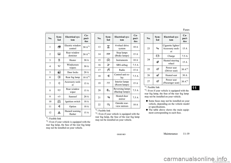
No.Sym-bolElectrical sys- temCa-
paci- ties1Electric window control30 A *12Rear window
demister30 A *13Heater30 A4Windscreen
wipers30 A5Door locks20 A6Rear fog lamp10 A *27Accessory sock-
et15 A8Rear windowwiper15 A9Sunroof20 A10Ignition switch10 A11Option10 A12Hazard warning flasher15 A*1: Fusible link
*2 : Even if your vehicle is equipped with the
rear fog lamp, the fuse of the rear fog lamp
may not be installed on your vehicle.
No.Sym- bolElectrical sys- temCa-
paci- ties134-wheel drive system10 A14Stop lamps
(Brake lamps)15 A15Instruments10 A16SRS airbag7.5 A17Radio15 A18Control unit re- lay7.5 A19Interior lamps
(Room lamps)15 A20Reversing lamps (Backup lamps)7.5 A21Heated door mirror7.5 A22Outside rear-view mirrors10 A*1 : Fusible link
*2 : Even if your vehicle is equipped with the
rear fog lamp, the fuse of the rear fog lamp
may not be installed on your vehicle.
No.Sym- bolElectrical sys- temCa-
paci- ties
23
Cigarette lighter/Accessory sock- et
15 A24
Charge7.5 AHeated steeringwheel15 A25Power seat
(Driver seat)30 A *126Heated seat30 A27Power seat
(Passenger seat)30 A *1*1
: Fusible link
*2 : Even if your vehicle is equipped with the
rear fog lamp, the fuse of the rear fog lamp
may not be installed on your vehicle.
l Some fuses may not be installed on your
vehicle, depending on the vehicle model
or specifications.
l The table above shows the main equip-
ment corresponding to each fuse.
Fuses
11-19OGGE18E1Maintenance11