bulb MITSUBISHI OUTLANDER PHEV 2018 Owner's Manual (in English)
[x] Cancel search | Manufacturer: MITSUBISHI, Model Year: 2018, Model line: OUTLANDER PHEV, Model: MITSUBISHI OUTLANDER PHEV 2018Pages: 538, PDF Size: 25.01 MB
Page 204 of 538
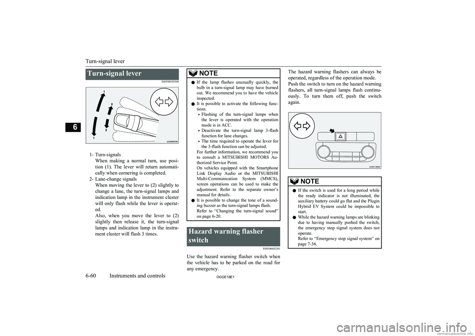
Turn-signal leverE00506502948
1- Turn-signalsWhen making a normal turn, use posi-
tion (1). The lever will return automati- cally when cornering is completed.
2- Lane-change signals When moving the lever to (2) slightly to
change a lane, the turn-signal lamps and indication lamp in the instrument clusterwill only flash while the lever is operat- ed.
Also, when you move the lever to (2)
slightly then release it, the turn-signal
lamps and indication lamp in the instru- ment cluster will flash 3 times.
NOTEl If the lamp flashes unusually quickly, the
bulb in a turn-signal lamp may have burned out. We recommend you to have the vehicle
inspected.
l It is possible to activate the following func-
tions.
• Flashing of the turn-signal lamps when
the lever is operated with the operation
mode is in ACC.
• Deactivate the turn-signal lamp 3-flash
function for lane changes.
• The time required to operate the lever for
the 3-flash function can be adjusted.
For further information, we recommend you
to consult a MITSUBISHI MOTORS Au-
thorized Service Point.
On vehicles equipped with the Smartphone
Link Display Audio or the MITSUBISHI
Multi-Communication System (MMCS),
screen operations can be used to make the adjustment. Refer to the separate owner’s
manual for details.
l It is possible to change the tone of a sound-
ing buzzer as the turn-signal lamps flash.
Refer to “Changing the turn-signal sound”
on page 6-20.Hazard warning flasher
switch E00506602301
Use the hazard warning flasher switch when
the vehicle has to be parked on the road for
any emergency.
The hazard warning flashers can always be
operated, regardless of the operation mode.
Push the switch to turn on the hazard warning flashers, all turn-signal lamps flash continu-
ously. To turn them off, push the switch
again.NOTEl If the switch is used for a long period while
the ready indicator is not illuminated, theauxiliary battery could go flat and the Plugin
Hybrid EV System could be impossible to start.
l While the hazard warning lamps are blinking
due to having manually pushed the switch,
the emergency stop signal system does not
operate.
Refer to “Emergency stop signal system” on page 7-36.
Turn-signal lever
6-60OGGE18E1Instruments and controls6
Page 238 of 538
NOTElWhen moving out of mud, sand or fresh
snow, pressing the accelerator pedal may not
allow the Plug-in Hybrid EV system output to increase. In such situations, switching to
“4WD LOCK” with the 4WD lock switch and temporarily turning off the Active Sta- bility Control (ASC) with the “ASC OFF”
switch will make it easier to move out your vehicle.
Refer to “Operation under adverse driving
conditions: If your vehicle becomes stuck in sand, mud or snow” on page 9-20.
Climbing/descending sharp
grades
Your vehicle may not provide sufficient hill
climbing ability and regenerative brake on steep slope. Avoid driving on steep slopes
even though the vehicle is a 4-wheel drive vehicle.
Inspection and maintenance
following rough roadoperation E00606701407
After operating the vehicle in rough road
conditions, be sure to perform the following inspection and maintenance procedures:
l Check that the vehicle has not been dam-
aged by rocks, gravel, etc.
l Carefully wash the vehicle with water.
Drive the vehicle slowly while lightly
depressing the brake pedal in order to dry out the brakes. If the brakes still do
not function properly, we recommend you to have the brakes checked as soon
as possible.
l Remove the insects, dried grass, etc.
clogging the radiator core.
l Check the inside of the vehicle. If water
entry is found, dry the carpet etc.
l Inspect the headlamps. If the headlamp
bulb is flooded with water, we recom-
mend you to have it drained.Cautions on handling of 4-
wheel drive vehicles E00606801844
Tyres and wheels
Since the driving torque can be applied to the
4 wheels, the driving performance of the ve- hicle when operating in 4-wheel drive is
greatly affected by the condition of the tyres.
Pay close attention to the tyres.
l Install only the specified tyres on all
wheels. Refer to “Tyres and wheels” on page 12-08.
l Be sure all 4 tyres and wheels are the
same size and type.
When it is necessary to replace any of
the tyres or wheels, replace all 4 tyres.
l All tyres should be rotated before the
wear difference between the front and
rear tyres is recognizable.
Good vehicle performance cannot be expec- ted if there is a difference in wear between tyres. Refer to “Tyre rotation” on page 11-11.
l Check the tyre inflation pressure regular-
ly.CAUTIONl Always use tyres of the same size, same
type, and same brand, and which have no wear differences. Using tyres of differentsize, type, brands or degree of wear, will in-
crease the differential oil temperature, result-
ing in possible damage to the driving sys-
tem. Further, the drive train will be subjec- ted to excessive loading possibly leading tooil leakage, component seizure, or other seri-
ous faults.
Inspection and maintenance following rough road operation
7-24OGGE18E1Starting and driving7
Page 447 of 538
Service precautions........................................................................... 11-02
Catalytic converter............................................................................ 11-03
Bonnet............................................................................................... 11-04
Engine oil.......................................................................................... 11-05 Engine coolant/Plug-in hybrid EV system coolant........................... 11-06
Washer fluid...................................................................................... 11-08
Brake fluid.........................................................................................11-08
Auxiliary battery............................................................................... 11-09
Tyres..................................................................................................11-10 Wiper blade rubber replacement....................................................... 11-13
General maintenance......................................................................... 11-15
Fusible links...................................................................................... 11-15
Fuses..................................................................................................11-16
Replacement of lamp bulbs............................................................... 11-23Maintenance
OGGE18E111
Page 461 of 538
NOTElDo not allow the wiper arm to fall onto the
window glass; it could damage the glass.
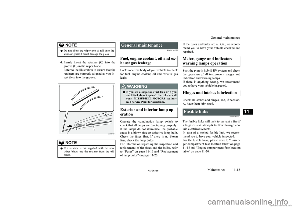
4. Firmly insert the retainer (C) into the
groove (D) in the wiper blade.
Refer to the illustration to ensure that the retainers are correctly aligned as you in-
sert them into the groove.
NOTEl If a retainer is not supplied with the new
wiper blade, use the retainer from the old
blade.General maintenance
E01002701556
Fuel, engine coolant, oil and ex- haust gas leakage
Look under the body of your vehicle to check
for fuel, engine coolant, oil and exhaust gas
leaks.
WARNINGl If you see a suspicious fuel leak or if you
smell fuel, do not operate the vehicle; call
your MITSUBISHI MOTORS Author-
ized Service Point for assistance.
Exterior and interior lamp op-
eration
Operate the combination lamp switch to
check that all lamps are functioning properly.
If the lamps do not illuminate, the probable cause is a blown fuse or defective lamp bulb.
Check the fuses first. If there is no blown
fuse, check the lamp bulbs.
For information regarding the inspection and
replacement of the fuses and the bulbs, refer
to “Fuses” on page 11-16 and “Replacement
of lamp bulbs” on page 11-23.
If the fuses and bulbs are all OK, we recom-
mend you to have your vehicle checked and repaired.
Meter, gauge and indicator/ warning lamps operation
Start the plug-in hybrid EV system and check the operation of all instruments, gauges and
indication and warning lamps.
If there is anything wrong, we recommend
you to have your vehicle inspected.
Hinges and latches lubrication
Check all latches and hinges, and, if necessa- ry, have them lubricated.
Fusible links
E01002901633
The fusible links will melt to prevent a fire if
a large current attempts to flow through cer- tain electrical systems.
In case of a melted fusible link, we recom- mend you to have your vehicle inspected.For the fusible links, please refer to “Passen-
ger compartment fuse location table” on page
11-18 and “Engine compartment fuse location
table” on page 11-20.
General maintenance
11-15OGGE18E1Maintenance11
Page 469 of 538
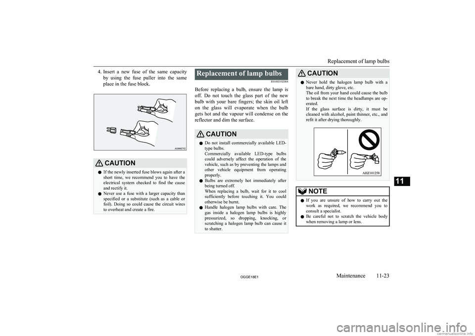
4.Insert a new fuse of the same capacity
by using the fuse puller into the same
place in the fuse block.CAUTIONl If the newly inserted fuse blows again after a
short time, we recommend you to have the electrical system checked to find the causeand rectify it.
l Never use a fuse with a larger capacity than
specified or a substitute (such as a cable or
foil). Doing so could cause the circuit wires
to overheat and create a fire.Replacement of lamp bulbs
E01003102004
Before replacing a bulb, ensure the lamp is off. Do not touch the glass part of the new
bulb with your bare fingers; the skin oil left
on the glass will evaporate when the bulb gets hot and the vapour will condense on the
reflector and dim the surface.CAUTIONl Do not install commercially available LED-
type bulbs.
Commercially available LED-type bulbs
could adversely affect the operation of the vehicle, such as by preventing the lamps andother vehicle equipment from operating
properly.
l Bulbs are extremely hot immediately after
being turned off.
When replacing a bulb, wait for it to cool sufficiently before touching it. You couldotherwise be burnt.
l Handle halogen lamp bulbs with care. The
gas inside a halogen lamp bulbs is highly
pressurized, so dropping, knocking, or
scratching a halogen lamp bulb can cause it to shatter.CAUTIONl Never hold the halogen lamp bulb with a
bare hand, dirty glove, etc.
The oil from your hand could cause the bulb to break the next time the headlamps are op-
erated.
If the glass surface is dirty, it must be cleaned with alcohol, paint thinner, etc., and
refit it after drying thoroughly.NOTEl If you are unsure of how to carry out the
work as required, we recommend you to consult a specialist.
l Be careful not to scratch the vehicle body
when removing a lamp or lens.
Replacement of lamp bulbs
11-23OGGE18E1Maintenance11
Page 470 of 538
NOTElWhen it rains or when the vehicle has been
washed, the inside of the lens sometimes be-
comes foggy. This is the same phenomenon as when window glass mists up on a humid
day, and does not indicate a functional prob- lem.
When the lamp is switched on, the heat will remove the fog. However, if water gathers
inside the lamp, we recommend you to have the lamp checked.Bulb location and capacity
E01003200333
When replacing a bulb, use a new bulb with
the same wattage and colour.
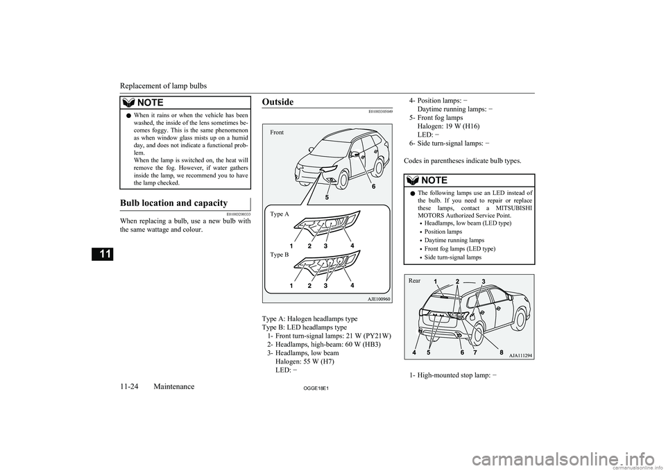
Outside
E01003305049
Type A: Halogen headlamps type
Type B: LED headlamps type 1- Front turn-signal lamps: 21 W (PY21W)
2- Headlamps, high-beam: 60 W (HB3)
3- Headlamps, low beam Halogen: 55 W (H7)
LED: −
4- Position lamps: −
Daytime running lamps: −
5- Front fog lamps Halogen: 19 W (H16)
LED: −
6- Side turn-signal lamps: −
Codes in parentheses indicate bulb types.NOTEl The following lamps use an LED instead of
the bulb. If you need to repair or replacethese lamps, contact a MITSUBISHI
MOTORS Authorized Service Point.
• Headlamps, low beam (LED type)
• Position lamps
• Daytime running lamps
• Front fog lamps (LED type)
• Side turn-signal lamps
1- High-mounted stop lamp: −
Replacement of lamp bulbs
11-24OGGE18E1Maintenance11 Front
Type A
Type B Rear
Page 471 of 538
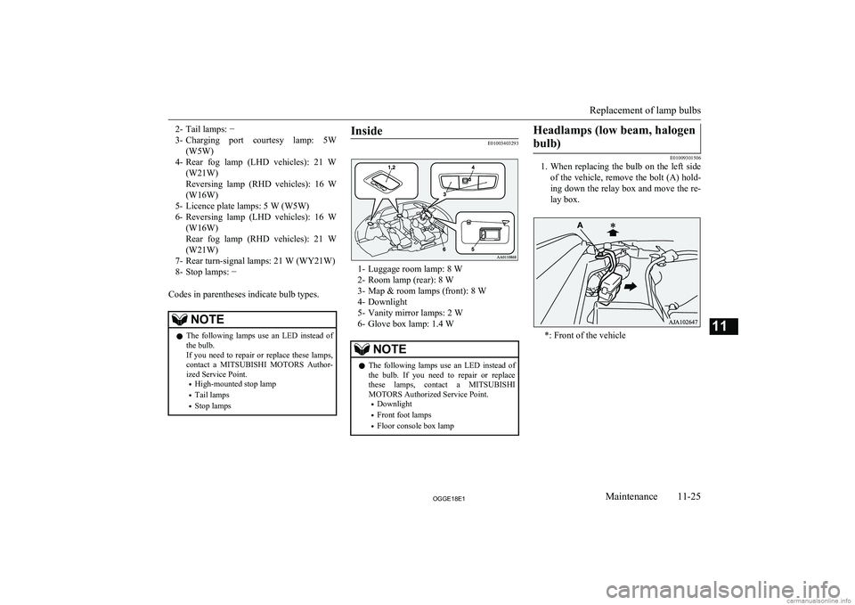
2- Tail lamps: −
3- Charging port courtesy lamp: 5W
(W5W)
4- Rear fog lamp (LHD vehicles): 21 W
(W21W)
Reversing lamp (RHD vehicles): 16 W
(W16W)
5- Licence plate lamps: 5 W (W5W)
6- Reversing lamp (LHD vehicles): 16 W
(W16W)
Rear fog lamp (RHD vehicles): 21 W (W21W)
7- Rear turn-signal lamps: 21 W (WY21W)
8- Stop lamps: −
Codes in parentheses indicate bulb types.NOTEl The following lamps use an LED instead of
the bulb.
If you need to repair or replace these lamps,
contact a MITSUBISHI MOTORS Author-
ized Service Point.
• High-mounted stop lamp
• Tail lamps
• Stop lampsInside
E01003403293
1- Luggage room lamp: 8 W
2- Room lamp (rear): 8 W
3- Map & room lamps (front): 8 W
4- Downlight
5- Vanity mirror lamps: 2 W
6- Glove box lamp: 1.4 W
NOTEl The following lamps use an LED instead of
the bulb. If you need to repair or replacethese lamps, contact a MITSUBISHI
MOTORS Authorized Service Point.
• Downlight
• Front foot lamps
• Floor console box lampHeadlamps (low beam, halogen
bulb)
E01009301506
1. When replacing the bulb on the left side
of the vehicle, remove the bolt (A) hold-ing down the relay box and move the re-
lay box.
*: Front of the vehicle
Replacement of lamp bulbs
11-25OGGE18E1Maintenance11
Page 472 of 538
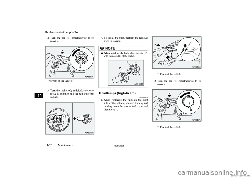
2.Turn the cap (B) anticlockwise to re-
move it.
*: Front of the vehicle
3. Turn the socket (C) anticlockwise to re-
move it, and then pull the bulb out of the
socket.
4. To install the bulb, perform the removal
steps in reverse.NOTEl When installing the bulb, align the tab (D)
with the notch (E) of the socket.Headlamps (high-beam)
E01009401288
1. When replacing the bulb on the right
side of the vehicle, remove the clip (A) holding down the washer tank spout and
then move it.
*: Front of the vehicle
2. Turn the cap (B) anticlockwise to re-
move it.
*: Front of the vehicle
Replacement of lamp bulbs
11-26OGGE18E1Maintenance11
Page 473 of 538
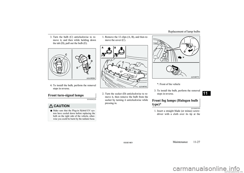
3.Turn the bulb (C) anticlockwise to re-
move it, and then while holding down
the tab (D), pull out the bulb (E).
4. To install the bulb, perform the removal
steps in reverse.
Front turn-signal lamps
E01003802320
CAUTIONl Make sure that the Plug-in Hybrid EV sys-
tem have cooled down before replacing the bulb on the right side of the vehicle, other-wise you could be burnt by the radiator hose.1. Remove the 12 clips (A, B), and then re-
move the cover (C).
2. Turn the socket (D) anticlockwise to re-
move it, then remove the bulb from the socket by turning it anticlockwise while
pressing in.
*: Front of the vehicle
3. To install the bulb, perform the removal
steps in reverse.
Front fog lamps (Halogen bulb
type)*
E01004003498
1. Insert a straight blade (or minus) screw-
driver with a cloth over its tip at the
Replacement of lamp bulbs
11-27OGGE18E1Maintenance11
Page 474 of 538
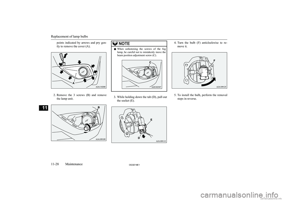
points indicated by arrows and pry gen-tly to remove the cover (A).
2. Remove the 3 screws (B) and remove
the lamp unit.
NOTEl When unfastening the screws of the fog
lamp, be careful not to mistakenly move thebeam position adjustment screw (C).
3. While holding down the tab (D), pull out
the socket (E).
4. Turn the bulb (F) anticlockwise to re-
move it.
5. To install the bulb, perform the removal
steps in reverse.
Replacement of lamp bulbs
11-28OGGE18E1Maintenance11