fuse MITSUBISHI OUTLANDER PHEV 2018 Owner's Manual (in English)
[x] Cancel search | Manufacturer: MITSUBISHI, Model Year: 2018, Model line: OUTLANDER PHEV, Model: MITSUBISHI OUTLANDER PHEV 2018Pages: 538, PDF Size: 25.01 MB
Page 4 of 538
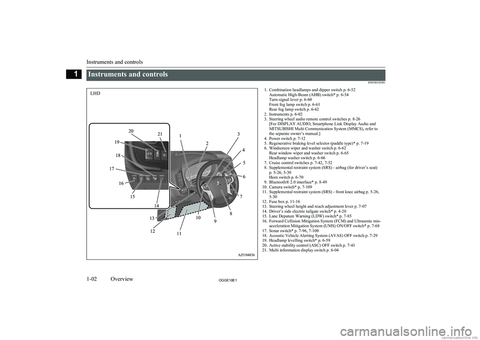
Instruments and controlsE085001020811. Combination headlamps and dipper switch p. 6-52Automatic High-Beam (AHB) switch* p. 6-54
Turn-signal lever p. 6-60
Front fog lamp switch p. 6-61
Rear fog lamp switch p. 6-62
2. Instruments p. 6-02
3. Steering wheel audio remote control switches p. 8-26 [For DISPLAY AUDIO, Smartphone Link Display Audio and
MITSUBISHI Multi Communication System (MMCS), refer to
the separate owner’s manual.]
4. Power switch p. 7-12
5. Regenerative braking level selector (paddle type)* p. 7-19
6. Windscreen wiper and washer switch p. 6-62 Rear window wiper and washer switch p. 6-65
Headlamp washer switch p. 6-66
7. Cruise control switches p. 7-42, 7-52
8. Supplemental restraint system (SRS) - airbag (for driver’s seat) p. 5-26, 5-30
Horn switch p. 6-70
9. Bluetooth® 2.0 interface* p. 8-49
10. Camera switch* p. 7-109
11. Supplemental restraint system (SRS) - front knee airbag p. 5-26, 5-30
12. Fuse box p. 11-16
13. Steering wheel height and reach adjustment lever p. 7-07
14. Driver’s side electric tailgate switch* p. 4-20
15. Lane Depature Warning (LDW) switch* p. 7-85
16. Forward Collision Mitigation System (FCM) and Ultrasonic mis- acceleration Mitigation System (UMS) ON/OFF switch* p. 7-68
17. Sonar switch* p. 7-96, 7-100
18. Acoustic Vehicle Alerting System (AVAS) OFF switch p. 7-29
19. Headlamp levelling switch* p. 6-59
20. Active stability control (ASC) OFF switch p. 7-41
21. Multi information display switch p. 6-04
Instruments and controls
1-02OGGE18E1Overview1LHD
Page 7 of 538
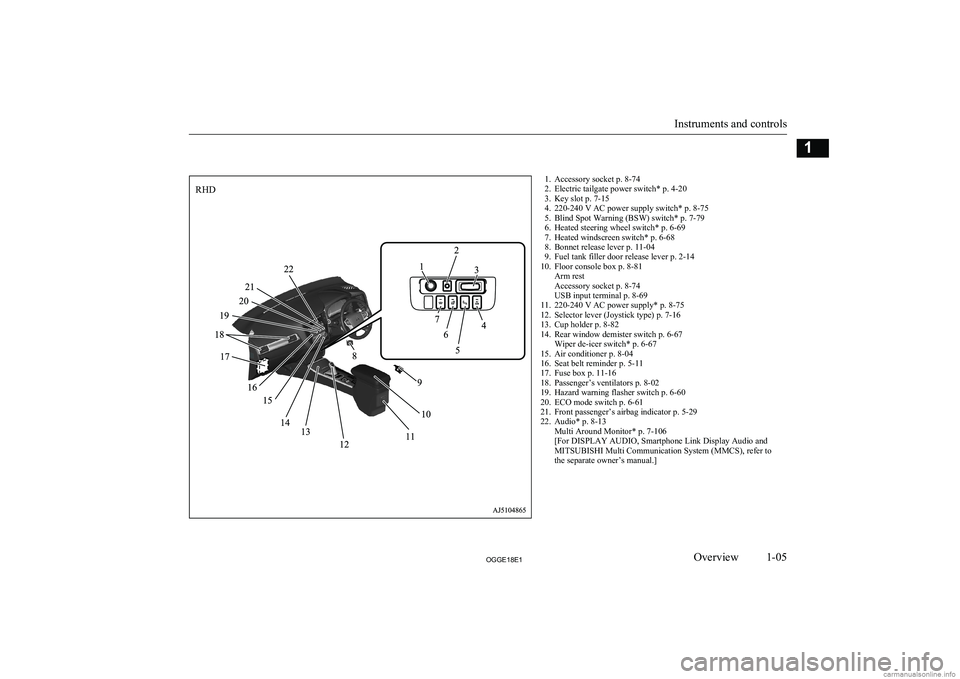
1. Accessory socket p. 8-74
2. Electric tailgate power switch* p. 4-20
3. Key slot p. 7-15
4. 220-240 V AC power supply switch* p. 8-75
5. Blind Spot Warning (BSW) switch* p. 7-79
6. Heated steering wheel switch* p. 6-69
7. Heated windscreen switch* p. 6-68
8. Bonnet release lever p. 11-04
9. Fuel tank filler door release lever p. 2-14
10. Floor console box p. 8-81 Arm rest
Accessory socket p. 8-74
USB input terminal p. 8-69
11. 220-240 V AC power supply* p. 8-75
12. Selector lever (Joystick type) p. 7-16
13. Cup holder p. 8-82
14. Rear window demister switch p. 6-67 Wiper de-icer switch* p. 6-67
15. Air conditioner p. 8-04
16. Seat belt reminder p. 5-11
17. Fuse box p. 11-16
18. Passenger’s ventilators p. 8-02
19. Hazard warning flasher switch p. 6-60
20. ECO mode switch p. 6-61
21. Front passenger’s airbag indicator p. 5-29
22. Audio* p. 8-13 Multi Around Monitor* p. 7-106
[For DISPLAY AUDIO, Smartphone Link Display Audio and
MITSUBISHI Multi Communication System (MMCS), refer to
the separate owner’s manual.]
Instruments and controls
1-05OGGE18E1Overview1RHD
Page 40 of 538
lThe installation of accessories, optional
parts, etc., should only be carried out
within the limits prescribed by law in your country, and in accordance with the
guidelines and warnings contained with-
in the documents accompanying this ve- hicle.
l Installing electric components incorrect-
ly could lead to a fire. Refer to the “Modification/alterations to the electri-
cal or fuel systems” section within this
owner’s manual.
l When installing the radio, for the re-
quired information (frequency, transmis-
sion output, installing procedure), con- sult a MITSUBISHI MOTORS Author-
ized Service Point.
If the frequency, transmission output and installing condition are not appropriate,
it can adversely affect the electronic de- vices and could lead to unsafe vehicle operation.
l Using a cellular phone or radio set inside
the vehicle without an external antenna
may cause electrical system interference, which could lead to unsafe vehicle oper-ation.
l Tyres and wheels which do not meet
specifications must not be used.
Refer to the “Specifications” section for information regarding wheel and tyre
sizes.Important points!
Due to large number of accessory and re-
placement parts of different manufactures
available in the market, it is not possible, not only for MITSUBISHI MOTORS , but also
for a MITSUBISHI MOTORS Authorized
Service Point, to check whether the attach- ment or installation of such parts affects theoverall safety of your vehicle.
Even when such parts are officially author-
ized, for example by a “general operators permit” (an appraisal for the part) or throughthe execution of the part in an officially ap-
proved manner of construction, or when a single operation permit following the attach-
ment or installation of such parts, it cannot be deduced from that alone, that the driving
safety of your vehicles has not been affected.
Consider also that there basically exists no li- ability on the part of the appraiser or the offi- cial. Maximum safety can only be ensured
with parts recommended, sold and fitted or
installed by a MITSUBISHI MOTORS au-
thorized Service Point ( MITSUBISHI
MOTORS GENUINE replacement parts and
MITSUBISHI MOTORS accessories). The
same also pertains to modifications of vehi- cles with respect to the production specifica- tions. For safety reasons, do not attempt anymodifications other than those that follow the
recommendations of a MITSUBISHI
MOTORS authorized Service Point.
Modification/alterations to
the electrical or fuel systems E00200401583
MITSUBISHI MOTORS CORPORATION
has always manufactured safe, high quality vehicles. In order to maintain this safety and
quality, it is important that any accessory that is to be fitted, or any modifications carried
out which involve the electrical or fuel sys- tems, should be carried out in accordancewith MITSUBISHI MOTORS guidelines.CAUTIONl If the wires interfere with the vehicle body
or improper installation methods are used (protective fuses not included, etc.), elec- tronic devices may be adversely affected, re-
sulting in a fire or other accident.Genuine parts
E00200500499
MITSUBISHI MOTORS has gone to great
lengths to bring you a superbly crafted auto-
mobile offering the highest quality and de- pendability.
Modification/alterations to the electrical or fuel systems
2-16OGGE18E1General information2
Page 92 of 538
WARNINGlTurn off the electric tailgate power switch
when not operating the electric tailgate.
If the switch is left on, someone’s hand or head could get caught if the electric tail- gate switch or close switch is accidentally
operated, or children play with the con-
trols.
l If the electric tailgate power switch is
turned off while the tailgate is operating,
it will stop moving and switch to manual
operation.
At this time, the electric tailgate could open or close suddenly, depending on its
position.CAUTIONl Do not apply excessive force on the electric
tailgate when opening or closing it. Doing so
could cause a breakdown.
l Do not start the Plug-in Hybrid EV System
while the tailgate is operating. The sudden
operation prevention mechanism could oper-
ate, making the electric tailgate stop inter-
mittently while it moves.NOTEl The electric tailgate cannot be opened when
the auxiliary battery is flat or disconnected.
If you want to open the electric tailgate, it can be opened by using the inside tailgate re-
lease.
Refer to “Inside tailgate release” on page
4-27.
l If the keyless entry system or close switch is
operated when the electric tailgate powerswitch is off, the warning buzzer sounds four
times to notify the driver that the electric
tailgate cannot be operated.
l The electric tailgate does not operate nor-
mally under the following conditions:
• When parked on an incline
• In strong winds
• When the electric tailgate is covered with
snow
l Repeated continuous operation between
opening and closing the electric tailgate will activate the built-in protection circuit and
switch the tailgate to manual operation.
l If the electric tailgate handle is operated
while the tailgate is operating or immediate- ly after it is closed, the tailgate will move in
the direction opposite to the one in which it
was operating.
l If the battery or fuse is replaced while the
electric tailgate is open, it cannot be closed
automatically.
In this case close the electric tailgate man- ually.Operating conditions
E00313101224
The electric tailgate can be opened automati-
cally when all of the following conditions are met.
l The operation mode is in OFF.
l The electric tailgate is completely
closed.
l The electric tailgate is unlocked.
l The operation mode is in ON with the
electrical parking switch is pressed.
l The electric tailgate is completely
closed.
l The electric tailgate is unlocked.
The electric tailgate can be closed automati-
cally when all of the following conditions are
met.
l The operation mode is in OFF.
l The electric tailgate is completely open.
l People, luggage, etc., are not touching
the sensors.
l The operation mode is in ON with the
electrical parking switch is pressed.
Electric tailgate*
4-22OGGE18E1Locking and unlocking4
Page 106 of 538
WARNINGlIf the auxiliary battery terminals are dis-
connected or the fuse for electric window
is replaced, the safety mechanism will be
cancelled.
If a hand or head got trapped, a serious injury could result.CAUTIONl The safety mechanism is cancelled just be-
fore the window is fully closed. This allows the window to close completely. Therefore be especially careful that no fingers are trap-
ped in the window.
l The safety mechanism is deactivated while
the switch is pulled up. Therefore be espe-
cially careful that fingers are not trapped in the door window opening.NOTEl The safety mechanism can be activated if the
driving conditions or other circumstancescause the driver’s door window to be subjec- ted to a physical shock similar to that caused
by a trapped hand or head.NOTEl If the auxiliary battery terminals are discon-
nected or the fuse for electric window is re-
placed, the safety mechanism will be cancel-
led and the door window will not automati- cally open/close completely.
If the window is open, repeatedly raise the
driver’s door window switch until the win-
dow has been fully closed. Following this, release the switch, raise the switch once again and hold it in this condition for at least
1 second, then release it. You should now be able to operate the driver’s door window in
the normal fashion.Sunroof*
E00302702445
The sunroof can only be operated with theoperation mode in “ON”.
To open
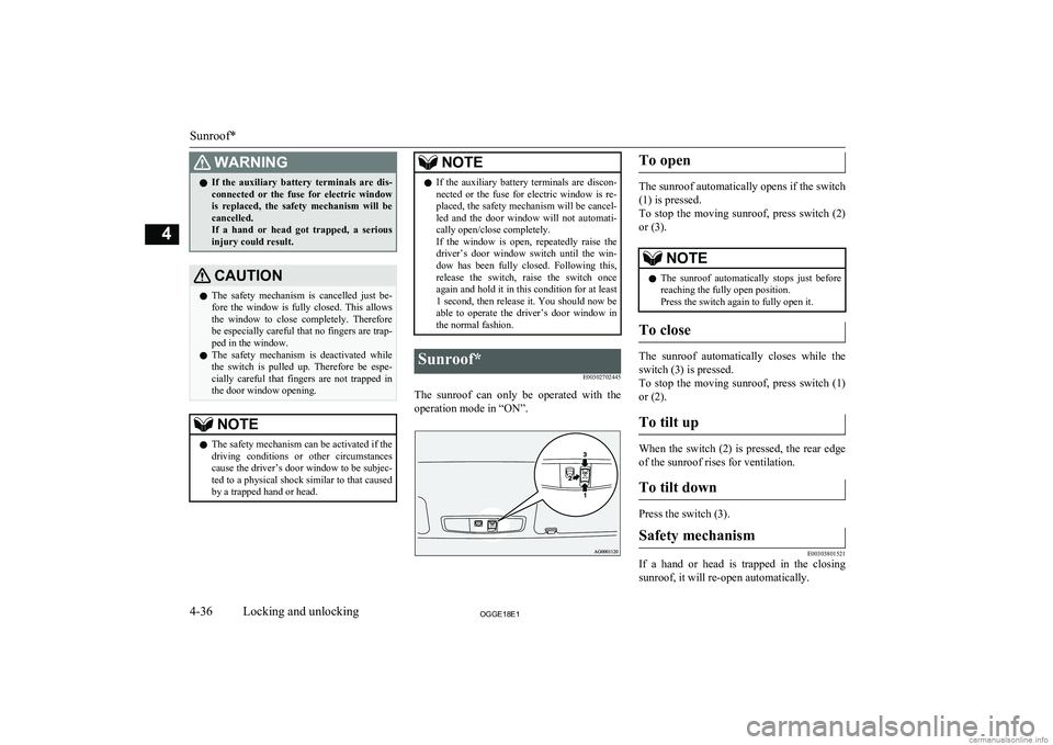
The sunroof automatically opens if the switch
(1) is pressed.
To stop the moving sunroof, press switch (2) or (3).
NOTEl The sunroof automatically stops just before
reaching the fully open position.
Press the switch again to fully open it.
To close
The sunroof automatically closes while the
switch (3) is pressed.
To stop the moving sunroof, press switch (1)
or (2).
To tilt up
When the switch (2) is pressed, the rear edge of the sunroof rises for ventilation.
To tilt down
Press the switch (3).
Safety mechanism
E00303801521
If a hand or head is trapped in the closing sunroof, it will re-open automatically.
Sunroof*
4-36OGGE18E1Locking and unlocking4
Page 383 of 538
SPEECH button
lPress this button to change to voice rec-
ognition mode.
While the system is in voice recognition
mode, “Listening” will appear on the au- dio display.
l If you press the button briefly while in
voice recognition mode, it will interrupt prompting and allow voice command in-
put.
Pressing the button longer will deacti-
vate the voice recognition mode.
l Pressing this button briefly during a call
will enable voice recognition and allow voice command input.
PICK-UP button
l Press this button when an incoming call
is received to answer the telephone.
l When another call is received during a
call, press this button to put the first call-
er on hold and talk to the new caller. • In such circumstances, you can press
the button briefly to switch between
callers. You will switch to the first
caller and the other caller will be put on hold.
• To establish a three-way call in such
situations, press the SPEECH button
to enter voice recognition mode and then say “Join calls”.
HANG-UP button
l Press this button when an incoming call
is received to refuse the call.
l Press this button during a call to end the
current call.
When another call is on hold, you will switch to that call.
l If this button is pressed in the voice rec-
ognition mode, the voice recognition
mode will be deactivated.
NOTEl When you press the SPEECH button to enter
voice recognition mode with a cellular
phone paired to the system, current informa- tion on the cellular phone, such as “remain- ing battery life,” “signal strength” or “roam-
ing,” will be displayed on the audio dis-
play.*
*: Some cellular phones will not send this
information to the Bluetooth ®
2.0 interface.
l Call waiting and three-way calls can be used
by the Bluetooth ®
2.0 interface, only if it is
possible to use those services with your cel- lular phone.
Microphone
Your voice will be recognized by a micro-
phone in the overhead console, allowing you to make hands-free calls with voice com-
mands.
NOTEl If a cellular phone is brought close to the mi-
crophone, it may create noise in the voice on
the phone. In such a case, take the cellular phone at a place as far as possible from the
microphone.Voice recognition function
E00727300514
The Bluetooth ®
2.0 interface is equipped
with a voice recognition function.
Simply say voice commands and you can
perform various operations and make or re- ceive hands-free calls.
With the Bluetooth ®
2.0 interface, voice rec-
ognition is possible for English, French,
Spanish, Italian, German, Dutch, Portuguese and Russian. The factory setting is “English” or “Russian.”
NOTEl If the voice command that you say differs
from the predefined command or cannot be recognised due to ambient noise or some
other reason, the Bluetooth ®
2.0 interface
will ask you for the voice command again up
to 3 times.
Bluetooth ®
2.0 interface*
8-51OGGE18E1For pleasant driving8
Page 421 of 538
2.Turn off all lamps, heater and other elec-
trical loads.
3. Set the parking brake firmly on each ve-
hicle. Set the gear of the other vehicle in
“P” (PARK) position (with A/T) or in
“N” (Neutral) position (with M/T) and
stop the engine.WARNINGl When connecting the jumper cable, stop
the engine in the other vehicle. Otherwise,
the cables or your clothes may be caught by the fan or drive belt and personal in-jury could result.
l The cooling fan turns on and off depend-
ing on the coolant temperature. Do not bring your hands close to the fan while
the engine is running or the Plug-in Hy- brid EV System is operating.
4. Open the bonnet, remove the fuse cover
of the main fuse block.
Refer to “Bonnet” on page 11-04 and
“Fuses: Engine compartment” on page
11-17.
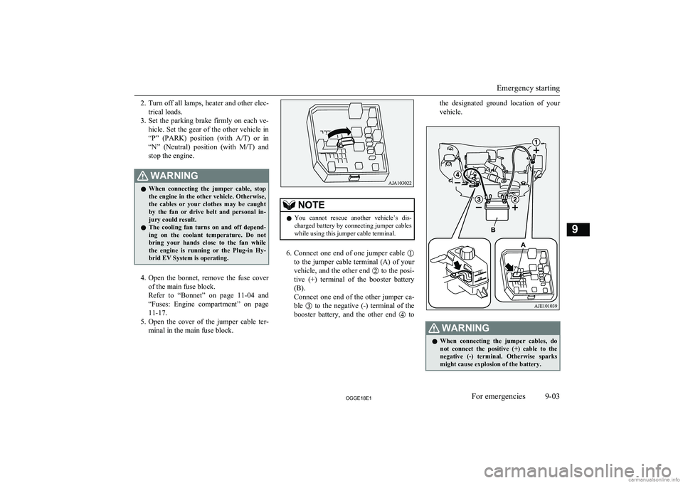
5. Open the cover of the jumper cable ter-
minal in the main fuse block.
NOTEl You cannot rescue another vehicle’s dis-
charged battery by connecting jumper cables
while using this jumper cable terminal.
6. Connect one end of one jumper cable
to the jumper cable terminal (A) of your
vehicle, and the other end
to the posi-
tive (+) terminal of the booster battery (B).
Connect one end of the other jumper ca- ble
to the negative (-) terminal of the
booster battery, and the other end
to
the designated ground location of your
vehicle.WARNINGl When connecting the jumper cables, do
not connect the positive (+) cable to the
negative (-) terminal. Otherwise sparks
might cause explosion of the battery.
Emergency starting
9-03OGGE18E1For emergencies9
Page 447 of 538
Service precautions........................................................................... 11-02
Catalytic converter............................................................................ 11-03
Bonnet............................................................................................... 11-04
Engine oil.......................................................................................... 11-05 Engine coolant/Plug-in hybrid EV system coolant........................... 11-06
Washer fluid...................................................................................... 11-08
Brake fluid.........................................................................................11-08
Auxiliary battery............................................................................... 11-09
Tyres..................................................................................................11-10 Wiper blade rubber replacement....................................................... 11-13
General maintenance......................................................................... 11-15
Fusible links...................................................................................... 11-15
Fuses..................................................................................................11-16
Replacement of lamp bulbs............................................................... 11-23Maintenance
OGGE18E111
Page 461 of 538
NOTElDo not allow the wiper arm to fall onto the
window glass; it could damage the glass.
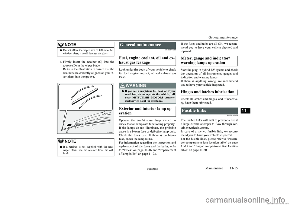
4. Firmly insert the retainer (C) into the
groove (D) in the wiper blade.
Refer to the illustration to ensure that the retainers are correctly aligned as you in-
sert them into the groove.
NOTEl If a retainer is not supplied with the new
wiper blade, use the retainer from the old
blade.General maintenance
E01002701556
Fuel, engine coolant, oil and ex- haust gas leakage
Look under the body of your vehicle to check
for fuel, engine coolant, oil and exhaust gas
leaks.
WARNINGl If you see a suspicious fuel leak or if you
smell fuel, do not operate the vehicle; call
your MITSUBISHI MOTORS Author-
ized Service Point for assistance.
Exterior and interior lamp op-
eration
Operate the combination lamp switch to
check that all lamps are functioning properly.
If the lamps do not illuminate, the probable cause is a blown fuse or defective lamp bulb.
Check the fuses first. If there is no blown
fuse, check the lamp bulbs.
For information regarding the inspection and
replacement of the fuses and the bulbs, refer
to “Fuses” on page 11-16 and “Replacement
of lamp bulbs” on page 11-23.
If the fuses and bulbs are all OK, we recom-
mend you to have your vehicle checked and repaired.
Meter, gauge and indicator/ warning lamps operation
Start the plug-in hybrid EV system and check the operation of all instruments, gauges and
indication and warning lamps.
If there is anything wrong, we recommend
you to have your vehicle inspected.
Hinges and latches lubrication
Check all latches and hinges, and, if necessa- ry, have them lubricated.
Fusible links
E01002901633
The fusible links will melt to prevent a fire if
a large current attempts to flow through cer- tain electrical systems.
In case of a melted fusible link, we recom- mend you to have your vehicle inspected.For the fusible links, please refer to “Passen-
ger compartment fuse location table” on page
11-18 and “Engine compartment fuse location
table” on page 11-20.
General maintenance
11-15OGGE18E1Maintenance11
Page 462 of 538
WARNINGlFusible links must not be replaced by any
other device. Failing to fit the correct fusi-
ble link may result in fire in the vehicle,
property destruction and serious or fatal injuries at any time.Fuses
E01003003332Fuse block location
E01011800035
To prevent damage to the electrical systemdue to short-circuiting or overloading, each individual circuit is provided with a fuse.
There are fuse blocks in the passenger com- partment and in the engine compartment.
Passenger compartment (LHD
vehicles)
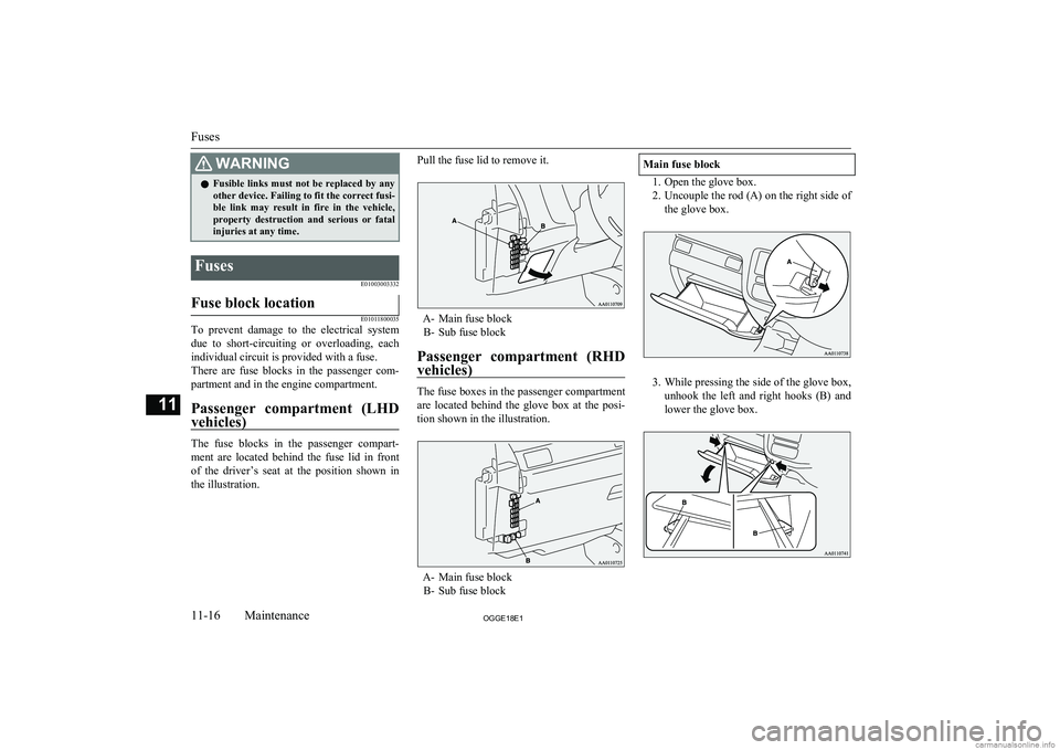
The fuse blocks in the passenger compart-
ment are located behind the fuse lid in front of the driver’s seat at the position shown in
the illustration.
Pull the fuse lid to remove it.
A- Main fuse block B- Sub fuse block
Passenger compartment (RHD vehicles)
The fuse boxes in the passenger compartment
are located behind the glove box at the posi- tion shown in the illustration.
A- Main fuse block B- Sub fuse block
Main fuse block
1. Open the glove box.
2. Uncouple the rod (A) on the right side of
the glove box.
3. While pressing the side of the glove box,
unhook the left and right hooks (B) and lower the glove box.
Fuses
11-16OGGE18E1Maintenance11