door lock MITSUBISHI PAJERO IV 2011 Owners Manual
[x] Cancel search | Manufacturer: MITSUBISHI, Model Year: 2011, Model line: PAJERO IV, Model: MITSUBISHI PAJERO IV 2011Pages: 377, PDF Size: 29.43 MB
Page 3 of 377
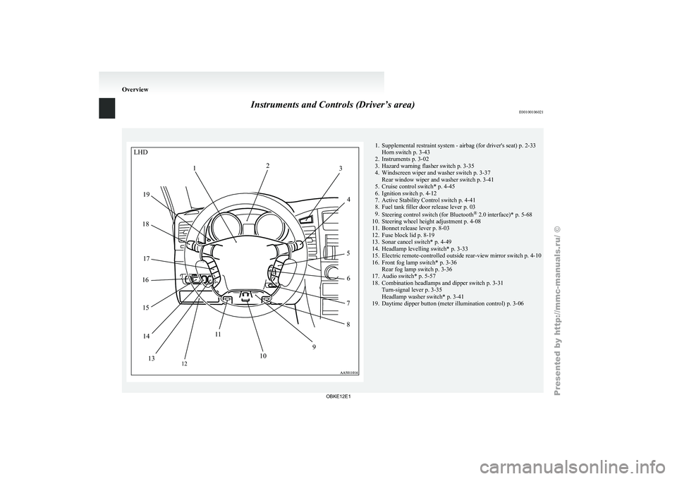
Instruments and Controls (Driver’s area)
E00100106021 1. Supplemental restraint system - airbag (for driver's seat) p. 2-33
Horn switch p. 3-43
2. Instruments p. 3-02
3. Hazard warning flasher switch p. 3-35
4.
Windscreen wiper and washer switch p. 3-37Rear window wiper and washer switch p. 3-41
5. Cruise control switch* p. 4-45
6. Ignition switch p. 4-12
7. Active Stability Control switch p. 4-41
8. Fuel tank filler door release lever p. 03
9. Steering control switch (for Bluetooth ®
2.0 interface)* p. 5-68
10. Steering wheel height adjustment p. 4-08
11. Bonnet release lever p. 8-03
12. Fuse block lid p. 8-19
13. Sonar cancel switch* p. 4-49
14. Headlamp levelling switch* p. 3-33
15. Electric remote-controlled outside rear-view mirror switch p. 4-10
16. Front fog lamp switch* p. 3-36 Rear fog lamp switch p. 3-36
17. Audio switch* p. 5-57
18. Combination headlamps and dipper switch p. 3-31 Turn-signal lever p. 3-35
Headlamp washer switch* p. 3-41
19. Daytime dipper button (meter illumination control) p. 3-06 OverviewLHD
2
1 3
4
5 6
7
8
9
10
1
1
12
13
14
15
16
17
18
19
OBKE12E1
Page 4 of 377
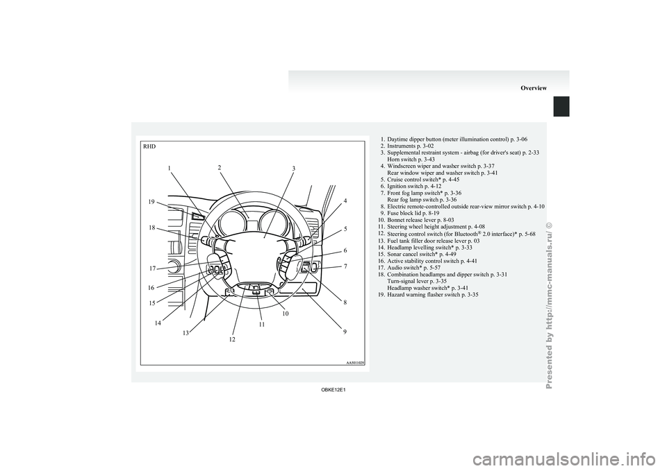
1. Daytime dipper button (meter illumination control) p. 3-06
2. Instruments p. 3-02
3. Supplemental restraint system - airbag (for driver's seat)
p. 2-33
Horn switch p. 3-43
4. Windscreen wiper and washer switch p. 3-37 Rear window wiper and washer switch p. 3-41
5. Cruise control switch* p. 4-45
6. Ignition switch p. 4-12
7. Front fog lamp switch* p. 3-36 Rear fog lamp switch p. 3-36
8. Electric remote-controlled outside rear-view mirror switch p. 4-10
9. Fuse block lid p. 8-19
10. Bonnet release lever p. 8-03
11. Steering wheel height adjustment p. 4-08
12. Steering control switch (for Bluetooth ®
2.0 interface)* p. 5-68
13. Fuel tank filler door release lever p. 03
14. Headlamp levelling switch* p. 3-33
15. Sonar cancel switch* p. 4-49
16. Active stability control switch p. 4-41
17. Audio switch* p. 5-57
18. Combination headlamps and dipper switch p. 3-31 Turn-signal lever p. 3-35
Headlamp washer switch* p. 3-41
19. Hazard warning flasher switch p. 3-35 OverviewRHD
1 2
3
45
6 7
8
9
12 10
1
1
13
14
15
16 17
18
19
OBKE12E1
Page 7 of 377
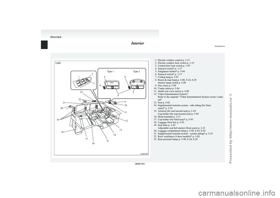
Interior
E00100204116LHD
Type 1
1 2
3 45
6
7
8
9
10
11
12
13
14
15
16
17
18
19
20
21 23
22 Type 2 1. Electric window control p. 1-15
2. Electric window lock switch
p. 1-15
3.
Central door lock switch p. 1-07
4. Sunroof switch* p. 1-17
5. Sunglasses holder* p. 5-94
6. Sunroof switch* p. 1-17
7. Ceiling lamp p. 5-87
8. Room & map lamp p. 5-88, 8-24, 8-29 Interior lamp switch p. 5-88
9. Sun visors p. 5-84
10. Vanity mirror p. 5-84
11. Inside rear-view mirror p. 4-08
12. Video Entertainment System* Refer to the separate “Video Entertainment System owner’s man-
ual”
13. Seat p. 2-02
14. Supplemental restraint system - side airbag (for front seats)* p. 2-33
15. Armrest (for rear/second seat) p. 2-10 Cup holder (for rear/second seat) p. 5-94
16. Head restraints p. 2-11
17. Cup holder (for third seat)* p. 5-95
18. Luggage floor box p. 5-93
19. Seat belts p. 2-20 Adjustable seat belt anchor (front seats) p. 2-21
20. Luggage compartment lamp p. 5-89, 8-24, 8-30
21. Supplemental restraint system - curtain airbag* p. 2-33
22. Roof ventilators (5-door models)* p. 5-02
23. Rear personal lamps p. 5-89, 8-24, 8-29 Overview
OBKE12E1
Page 8 of 377
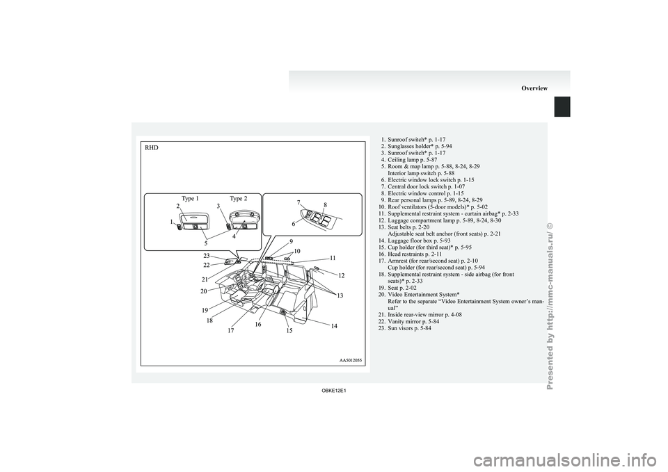
Type 1 Type 21. Sunroof switch* p. 1-17
2. Sunglasses holder* p. 5-94
3. Sunroof switch* p. 1-17
4.
Ceiling lamp p. 5-87
5. Room & map lamp p. 5-88, 8-24, 8-29 Interior lamp switch p. 5-88
6. Electric window lock switch p. 1-15
7. Central door lock switch p. 1-07
8. Electric window control p. 1-15
9. Rear personal lamps p. 5-89, 8-24, 8-29
10. Roof ventilators (5-door models)* p. 5-02
11. Supplemental restraint system - curtain airbag* p. 2-33
12. Luggage compartment lamp p. 5-89, 8-24, 8-30
13. Seat belts p. 2-20 Adjustable seat belt anchor (front seats) p. 2-21
14. Luggage floor box p. 5-93
15. Cup holder (for third seat)* p. 5-95
16. Head restraints p. 2-11
17. Armrest (for rear/second seat) p. 2-10 Cup holder (for rear/second seat) p. 5-94
18. Supplemental restraint system - side airbag (for front seats)* p. 2-33
19. Seat p. 2-02
20. Video Entertainment System* Refer to the separate “Video Entertainment System owner’s man-
ual”
21. Inside rear-view mirror p. 4-08
22. Vanity mirror p. 5-84
23. Sun visors p. 5-84 Overview
OBKE12E1
Page 15 of 377
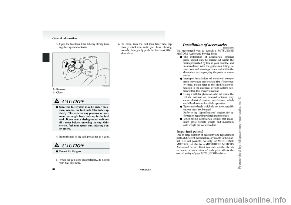
3. Open the fuel tank filler tube by slowly turn-
ing the cap anticlockwise. A- Remove
B- Close CAUTION
l
Since the
fuel system may be under pres-
sure, remove the fuel tank filler tube cap
slowly. This relieves any pressure or vac-
uum that might have built up in the fuel
tank. If you hear a hissing sound, wait un-
til it stops before removing the cap. Oth-
erwise, fuel may spray out, injuring you
or others.
4. Insert the gun in the tank port as far as it goes. CAUTION
l
Do not tilt the gun.
5. When the gun stops automatically, do not fill with fuel any more. 6.
To close,
turn the fuel tank filler tube cap
slowly clockwise
until you hear clicking
sounds, then gently push the fuel tank filler
door closed. Installation of accessories
E00200300774
We recommend you
to consult a MITSUBISHI
MOTORS Authorized Service Point.
l The installation of accessories, optional
parts, should only be carried out within the
limits prescribed by law in your country, and
in accordance with the guidelines fitting in-
structions and warnings contained within the
documents accompanying the parts or acces-
sories.
l Improper installation of electrical compo-
nents may cause an electrical fire if incorrect-
ly fitted. Please refer to the Modification/al-
teration to the electrical or fuel systems sec-
tion within this owner’s manual.
l Using a cellular phone or radio set inside the
vehicle without an external antenna may
cause electrical system interference, which
could lead to unsafe vehicle operation.
l Tyres and wheels which do not meet specifi-
cations must not be used.
Refer to the “Specifications” section for in-
formation regarding wheel and tyre sizes.
l When fitting accessories, ensure that maxi-
mum gross vehicle weight and maximum
axle weight are not exceeded.
Important points!
Due to large number of accessory and replacement
parts of different manufactures available in the mar-
ket, it is not possible, not only for MITSUBISHI
MOTORS, but also for a MITSUBISHI MOTORS
Authorized Service Point, to check whether the at-
tachment or installation of such parts affects the
overall safety of your MITSUBISHI-vehicle.
General information
04
OBKE12E1
Page 18 of 377
Keys..............................................................................................
1-02
Electronic immobilizer (Anti-theft starting system) .....................1-03
Keyless entry system*.................................................................. 1-04
Doors............................................................................................ 1-06
Central door locks ......................................................................... 1-07
“Child-protection” rear doors (5-door models) ............................1-08
Approach lamps*.......................................................................... 1-08
Backdoor....................................................................................... 1-09
Security alarm system* .................................................................1-10
Electric window control................................................................1-15 Rear side/quarter window ............................................................. 1-17
Sunroof* ....................................................................................... 1-17Locking and unlocking
1
OBKE12E1
Page 21 of 377
Keyless entry system*
E00300302085
Press the remote
control switch, and all doors (in-
cluding the backdoor) will be locked or unlocked
as desired. It is also possible to operate the outside
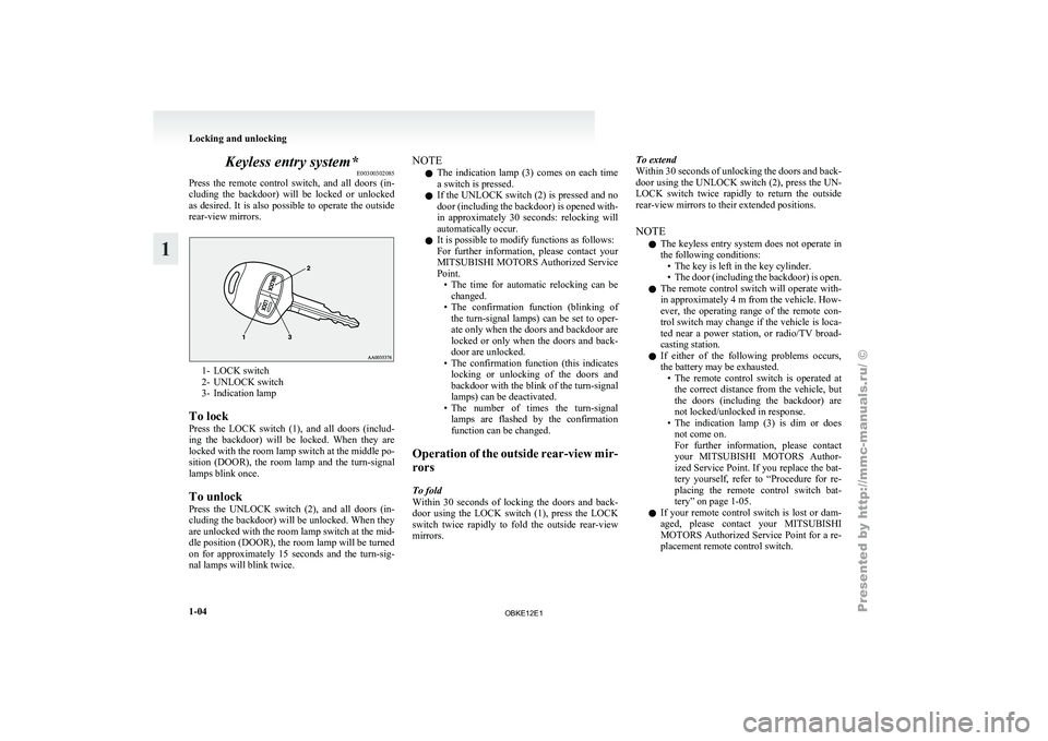
rear-view mirrors. 1- LOCK switch
2- UNLOCK switch
3-
Indication lamp
To lock
Press
the LOCK switch (1), and all doors (includ-
ing the backdoor) will be locked. When they are
locked with the room lamp switch at the middle po-
sition (DOOR), the room lamp and the turn-signal
lamps blink once.
To unlock
Press the UNLOCK switch (2), and all doors (in-
cluding the backdoor) will be unlocked. When they
are unlocked with the room lamp switch at the mid-
dle position (DOOR), the room lamp will be turned
on for approximately 15 seconds and the turn-sig-
nal lamps will blink twice. NOTE
l The
indication lamp
(3) comes on each time
a switch is pressed.
l If the UNLOCK switch (2) is pressed and no
door (including the backdoor) is opened with-
in approximately 30 seconds: relocking will
automatically occur.
l It is possible to modify functions as follows:
For further information, please contact your
MITSUBISHI MOTORS Authorized Service
Point.
• The time for automatic relocking can bechanged.
• The confirmation function (blinking of the turn-signal lamps) can be set to oper-
ate only when the doors and backdoor are
locked or only when the doors and back-
door are unlocked.
• The confirmation function (this indicates locking or unlocking of the doors and
backdoor with the blink of the turn-signal
lamps) can be deactivated.
• The number of times the turn-signal lamps are flashed by the confirmation
function can be changed.
Operation of the outside rear-view mir-
rors
To fold
Within 30 seconds of locking the doors and back-
door using the LOCK switch (1), press the LOCK
switch twice rapidly to fold the outside rear-view
mirrors. To extend
Within 30 seconds
of unlocking the doors and back-
door using the UNLOCK switch (2), press the UN-
LOCK switch twice rapidly to return the outside
rear-view mirrors to their extended positions.
NOTE
l The keyless entry system does not operate in
the following conditions:
• The key is left in the key cylinder.
• The door (including the backdoor) is open.
l The remote control switch will operate with-
in approximately 4 m from the vehicle. How-
ever, the operating range of the remote con-
trol switch may change if the vehicle is loca-
ted near a power station, or radio/TV broad-
casting station.
l If either of the following problems occurs,
the battery may be exhausted.
• The remote control switch is operated atthe correct distance from the vehicle, but
the doors (including the backdoor) are
not locked/unlocked in response.
• The indication lamp (3) is dim or does not come on.
For further information, please contact
your MITSUBISHI MOTORS Author-
ized Service Point. If you replace the bat-
tery yourself, refer to “Procedure for re-
placing the remote control switch bat-
tery” on page 1-05.
l If your remote control switch is lost or dam-
aged, please contact your MITSUBISHI
MOTORS Authorized Service Point for a re-
placement remote control switch. Locking and unlocking
1-04
1
OBKE12E1
Page 22 of 377
l
If you
wish to add a remote control switch,
we recommend you to contact a
MITSUBISHI MOTORS Authorized Service
Point.
A maximum of 4 remote control switches are
available for your vehicle.
Procedure for replacing the remote
control switch battery E00309500132
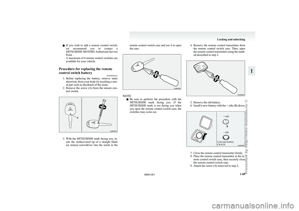
1. Before replacing the battery, remove static
electricity from
your body by touching a met-
al part such as doorknob of the room.
2. Remove the screw (A) from the remote con- trol switch. 3. With the MITSUBISHI mark facing you, in-
sert the
clothcovered tip of a straight blade
(or minus) screwdriver into the notch in the remote control switch case and use it to open
the case.
NOTE
l Be
sure to
perform the procedure with the
MITSUBISHI mark facing you. If the
MITSUBISHI mark is not facing you when
you open the remote control switch case, the
switches may come out. 4. Remove
the remote control transmitter from
the remote
control switch case. Then, open
the remote control transmitter using the meth-
od described in step 3. 5. Remove the old battery.
6. Install a
new
battery with the + side (B) down.
Coin type battery
CR1616
- side
+ side 7. Close the remote control transmitter firmly.
8. Place the remote control transmitter in the re-
mote control
switch case, then securely close
the remote control switch case.
9. Attach the screw (A) removed in step 2. Locking and unlocking
1-05 1
OBKE12E1
Page 23 of 377
10. Check the keyless entry system to see that it
works.
NOTE l You may
purchase a replacement battery at
an electric appliance store.
l A MITSUBISHI MOTORS Authorized Serv-
ice Point can replace the battery for you if
you prefer. CAUTION
l
When the
remote
control switch case is
opened, be careful to keep water, dust,
etc. out. Also, do not touch the internal
components. Doors
E00300401177 CAUTION
l
Make sure
the
doors are closed: driving
with doors not completely closed is dan-
gerous.
l Never leave children in the vehicle unat-
tended.
l Be careful not to lock the doors while the
key is inside the vehicle.
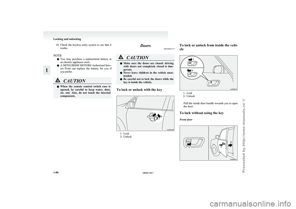
To lock or unlock with the key 1- Lock
2- UnlockTo
lock
or unlock from inside the vehi-
cle 1- Lock
2- Unlock
Pull the
inside door handle towards you to open
the door.
To lock without using the key
Front door Locking and unlocking
1-06
1
OBKE12E1
Page 24 of 377
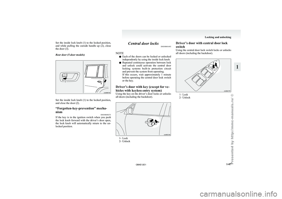
Set the inside lock knob (1) to the locked position,
and while pulling
the outside handle up (2), close
the door (3).
Rear door (5-door models) Set the inside lock knob (1) to the locked position,
and close the door (2).
“Forgotten-key-prevention” mecha-
nism
E00300600273
If the key is in the ignition switch when you push
the lock knob
forward with the driver’s door open,
the lock knob will automatically return to the un-
locked position. Central door locks
E00300801692
NOTE l Each
of the
doors can be locked or unlocked
independently by using the inside lock knob.
l Repeated continuous operation between lock
and unlock could activate the central door
locking systems built-in protection circuit
and prevent the system from operating.
If this occurs, wait approximately 1 minute
before operating the central door lock switch
or the key.
Driver’s door with key (except for ve-
hicles with keyless entry system)
Using the key on the driver’s door locks or unlocks
all doors (including the backdoor). 1- Lock
2- UnlockDriver’s door with central door lock
switch
Using the
central
door lock switch locks or unlocks
all doors (including the backdoor). 1- Lock
2- Unlock Locking and unlocking
1-07 1
OBKE12E1