tyre change MITSUBISHI PAJERO IV 2011 Owners Manual
[x] Cancel search | Manufacturer: MITSUBISHI, Model Year: 2011, Model line: PAJERO IV, Model: MITSUBISHI PAJERO IV 2011Pages: 377, PDF Size: 29.43 MB
Page 157 of 377
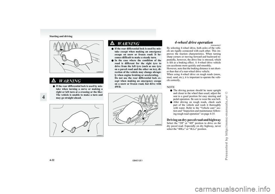
WARNING
l If the
rear differential lock is used by mis-
take when turning a curve or making a
right or left turn at a crossing or the like:
The vehicle is unable to make a turn and
may go straight ahead. WARNING
l If the rear
differential lock is used by mis-
take except when making an emergency
escape on snow or frozen road: It be-
comes difficult to make a steady turn.
l In the case where the condition of the
road is different for the right tyre to
drive from the left tyre (such as one tyre
on a paved road and the other on ice), di-
rection of the vehicle may change abrupt-
ly when engine braking or accelerating.
Do not use the rear differential lock ex-
cept when making an emergency escape
on a snow or frozen road, but drive with
4WD. 4-wheel drive operation
E00606600627
By selecting 4-wheel
drive, both axles of the vehi-
cle are rigidly connected with each other. This im-
proves the traction characteristics. When turning
sharp corners or moving forward and backward re-
peatedly, however, the drive line is stressed, which
is felt as a braking effect. A 4-wheel drive vehicle
can accelerate more quickly and smoothly.
However, note that the braking distance is not short-
er than that of a rear-wheel drive vehicle.
When using 4-wheel drive on rough roads (snow,
mud, sand, etc.), it is important to operate the vehi-
cle correctly.
NOTE
l The driving posture should be more upright
and closer to the wheel than usual; adjust the
seat to a good position for easy steering and
pedal operation. Be sure to wear the seat belt.
l After driving on rough roads, check each
part of the vehicle and wash it thoroughly
with water. Refer to the “Vehicle care” sec-
tion and “Inspection and maintenance follow-
ing rough road operation” on page 4-35.
Driving on dry paved road and highway
Select the “2H” or “4H” position to drive on the
dry paved road. Especially on dry highway, never
select the “4HLc” or “4LLc” position. Starting and driving
4-32
4
OBKE12E1
Page 159 of 377
l
Driving over
roads in coastal areas or roads
on which anti-skid preparations have been
spread can cause rust on the vehicle; wash
the vehicle thoroughly as soon as possible af-
ter such use.
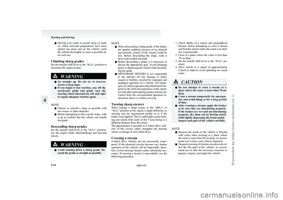
Climbing sharp grades
Set the transfer shift lever to the “4LLc” position to
maximize the engine torque. WARNING
l Go
straight
up.
Do not try to traverse
across a steep slope.
l If you begin to lose traction, ease off the
accelerator pedal and gently turn the
steering wheel alternatively left and right
to regain adequate traction again.
NOTE l Choose
as smooth
a slope as possible with
few stones or other obstacles.
l Before attempting to drive up the slope, walk
it up to confirm that the vehicle can handle
the grade.
Descending sharp grades
Set the transfer shift lever to the “4LLc” position,
use the engine brake (downshifting) and descend
slowly. WARNING
l Avoid
snaking
down
a sharp grade. De-
scend the grade as straight as possible. NOTE
l When descending a sharp grade, if the brakes
are
applied suddenly
because of an obstacle
encountered, control of the vehicle could be
lost. Before descending the slope, walk it
down and confirm the path.
l Before descending a grade, it is necessary to
choose the appropriate gear. Avoid changing
gears or depressing the clutch while descend-
ing the grade.
l MITSUBISHI MOTORS is not responsible
to the operator for any damage or injury
caused or liability incurred by improper and
negligent operation of a vehicle. All techni-
ques of vehicle operation described herein de-
pend on the skill and experience of the opera-
tor and other participating parties and any de-
viation from the recommended operation in-
structions above is at their own risk.
Turning sharp corners
When turning a sharp corner in the “4HLc” or
“4LLc” position at low speed, a slight difference in
steering may be experienced similar to as if the
brakes were applied. This is called tight corner brak-
ing and results from each of the 4 tyres being at a
different distance from the corner.
The phenomenon is peculiar to 4-wheel drive vehi-
cles. If this occurs, either straighten the steering
wheel, or change to rear-wheel drive.
Crossing a stream
4-wheel drive vehicles are not necessarily water-
proof. If the electrical circuits become wet, further
operation of the vehicle will be impossible; there-
fore, avoid crossing streams unless absolutely nec-
essary. If crossing a stream is unavoidable, use the
following procedure: 1. Check depths of a stream and geographical
features before
attempting to cross a stream
and ford the stream where the water is as shal-
low as practicable.
2. Cross at a place where the water is less than 70 cm deep.
3. Set the transfer shift lever to the “4LLc” po- sition.
4. Drive slowly at a speed of approximately 5 km/h (3 mph) to avoid splashing too much
water. CAUTION
l
Do not
attempt
to cross a stream at a
place where the water is more than 70 cm
deep.
l Cross a stream temporarily for emergen-
cies and avoid doing so for a long period
of time.
l After crossing a stream, apply the brakes
to be sure they are functioning properly.
If the brakes are wet and not functioning
properly, dry them out by driving slowly
while lightly depressing the brake pedal.
Inspect each part of the vehicle carefully.
NOTE l Because
the inside
of the vehicle is flooded
with water when crossing at a place where
the water is more than 50 cm deep, we recom-
mend you to have your vehicle inspected.
l Frequent crossing of streams can adversely af-
fect the life span of the vehicle; we recom-
mend you to take the necessary measures to
prepare, inspect, and repair the vehicle. Starting and driving
4-34
4
OBKE12E1
Page 175 of 377
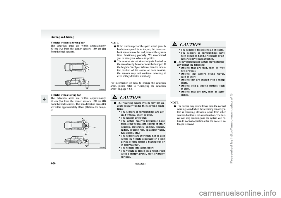
Vehicles without a towing bar
The detection areas
are within approximately
50 cm (A) from the corner sensors, 150 cm (B)
from the back sensors. Vehicles with a towing bar
The detection
areas
are within approximately
50 cm (A) from the corner sensors, 150 cm (B)
from the back sensors. The non-detection areas (C)
are within approximately 20 cm (D) from the bump-
er. NOTE
l If
the rear
bumper or the spare wheel garnish
has been exposed to an impact, the corner or
back sensors may fail and prevent the system
from functioning properly. We recommend
you to have your vehicle inspected.
l The sensors do not detect objects located in
the area directly below or near the bumper. If
the height of an object is lower than the moun-
ted position of the corner or back sensors,
the sensors may not continue detecting it
even if they detected it initially.
For information on how to change the detection
areas, please refer to “Changing the detection
areas” on page 4-52. CAUTION
l
The reversing
sensor
system may not op-
erate properly under the following condi-
tions: • The sensors or surroundings are cov-ered with ice, snow, or mud.
• The sensors are frozen.
• The system receives ultrasonic noise from other sources (the horns of other
vehicles, motorcycle engines, brakes,
radios, pouring rain, splashing water,
tyre chains, etc.).
• The sensors are extremely hot or cold (while the vehicle is parked for a long
period of time under a blazing sun or
in cold weather).
• The vehicle tilts significantly.
• The vehicle is driven on a rough road (with a bumpy, gravel, hilly, or grassy
surface). CAUTION
• The vehicle is too close to an obstacle.
• The sensors
or
surroundings have
been wiped by hand, or stickers or ac-
cessories have been attached.
l The reversing sensor system may not prop-
erly detect the following:
• Objects that are thin, such as wirenets or ropes.
• Objects that absorb sound waves, such as snow.
• Objects that are shaped with a sharp angle.
• Objects with a smooth surface, such as glass.
• Objects that are low, such as kerb- stones.
NOTE l The
buzzer may
sound lower than the normal
warning sound when the reversing sensor sys-
tem is receiving ultrasonic noise from other
sources, but this is not a malfunction. The buz-
zer will stop sounding and the system will re-
turn to normal operation after the noise is no
longer received. Starting and driving
4-50
4
OBKE12E1
Page 183 of 377
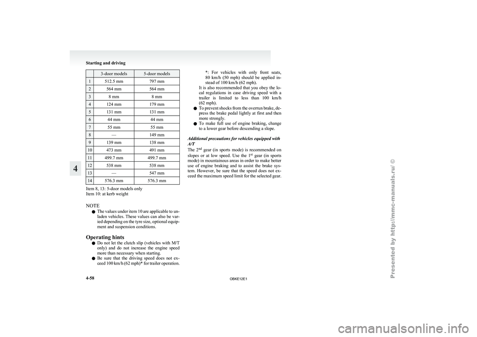
3-door models 5-door models
1 512.5 mm
797 mm2 564 mm
564 mm3 8 mm
8 mm4 124 mm
179 mm5 131 mm
131 mm6 44 mm
44 mm7 55 mm
55 mm8 —
149 mm9 139 mm
138 mm10 473 mm
491 mm11 499.7 mm
499.7 mm12 538 mm
538 mm13 —
547 mm14 576.3 mm
576.3 mmItem 8, 13: 5-door models only
Item 10: at kerb weight
NOTE
l The
values under
item 10 are applicable to un-
laden vehicles. These values can also be var-
ied depending on the tyre size, optional equip-
ment and suspension conditions.
Operating hints l Do not let the clutch slip (vehicles with M/T
only) and do not increase the engine speed
more than necessary when starting.
l Be sure that the driving speed does not ex-
ceed 100 km/h (62 mph)* for trailer operation. *: For vehicles with only front seats,
80
km/h
(50
mph) should be applied in-
stead of 100 km/h (62 mph).
It is also recommended that you obey the lo-
cal regulations in case driving speed with a
trailer is limited to less than 100 km/h
(62 mph).
l To prevent shocks from the overrun brake, de-
press the brake pedal lightly at first and then
more strongly.
l To make full use of engine braking, change
to a lower gear before descending a slope.
Additional precautions for vehicles equipped with
A/T
The 2 nd
gear (in sports mode) is recommended on
slopes or at low speed. Use the 1 st
gear (in sports
mode) in mountainous areas in order to make better
use of engine braking and to assist the brake sys-
tem. However, be sure that the speed does not ex-
ceed the maximum speed limit for the selected gear. Starting and driving
4-58
4
OBKE12E1
Page 282 of 377
If the vehicle breaks down
............................................................ 6-02
Emergency starting ....................................................................... 6-02
Engine overheating ....................................................................... 6-04
Bleeding the fuel system (diesel-powered vehicles only) ............6-06
Removal of water from the fuel filter (diesel-powered vehicles only) ........................................................................... 6-06
Tool, jack and jack handle ............................................................ 6-07
How to change a tyre .................................................................... 6-09
Towing.......................................................................................... 6-15
Operation under adverse driving conditions .................................6-18For emergencies
6
OBKE12E1
Page 290 of 377

To use the jack handle
E00802400023
1. While pushing the
snap pin (A), remove the
inside handle (B). 2. With the snap pin (C) pushed, insert the in-
side handle until it is locked. How to change a tyre
E00801201601
Before changing a
tyre, first stop your vehicle in a
safe, flat location. 1. Park the vehicle on level and stable ground.
2. Set the parking brake firmly.
3. On vehicles with M/T, turn the ignitionswitch to the “LOCK” position, move the
gearshift lever to the “R” (Reverse) position.
On vehicles with A/T, move the selector lev-
er to the “P” (PARK) position, turn the igni-
tion key to the “LOCK” position.
4. Turn on the hazard warning flashers and set up a warning triangle, flashing signal lamp,
etc., at an adequate distance from the vehi-
cle, and have all your passengers leave the ve-
hicle.
5. To prevent the vehicle from rolling when it is raised on the jack, place chocks or blocks
(A) at the tyre that is diagonally opposite
from the tyre (B) you are changing. WARNING
l Be sure to
apply chocks or blocks to the
correct tyre when jacking up the vehicle.
If the vehicle moves while jacked up, the
jack could slip out of position, leading to
an accident.
NOTE l The
chocks shown
in the illustration do not
come with your vehicle. It is recommended
that you keep one in the vehicle for use if nee-
ded.
l If chocks are not available, use stones or any
other objects that are large enough to hold
the wheel in position.
6. Get the spare wheel, jack, jack handle and wheel nut wrench ready. Refer to “Tool, jack
and jack handle” on page 6-07.
Spare wheel information E00803600266
Check the air pressure of the spare tyre frequently
and make sure
it is ready for emergency use at any
time.
Maintaining the spare wheel at the highest speci-
fied air pressure will ensure that it can always be
used under any conditions (city/high-speed driving,
varying load weight, etc.). For emergencies
6-09 6
OBKE12E1
Page 292 of 377
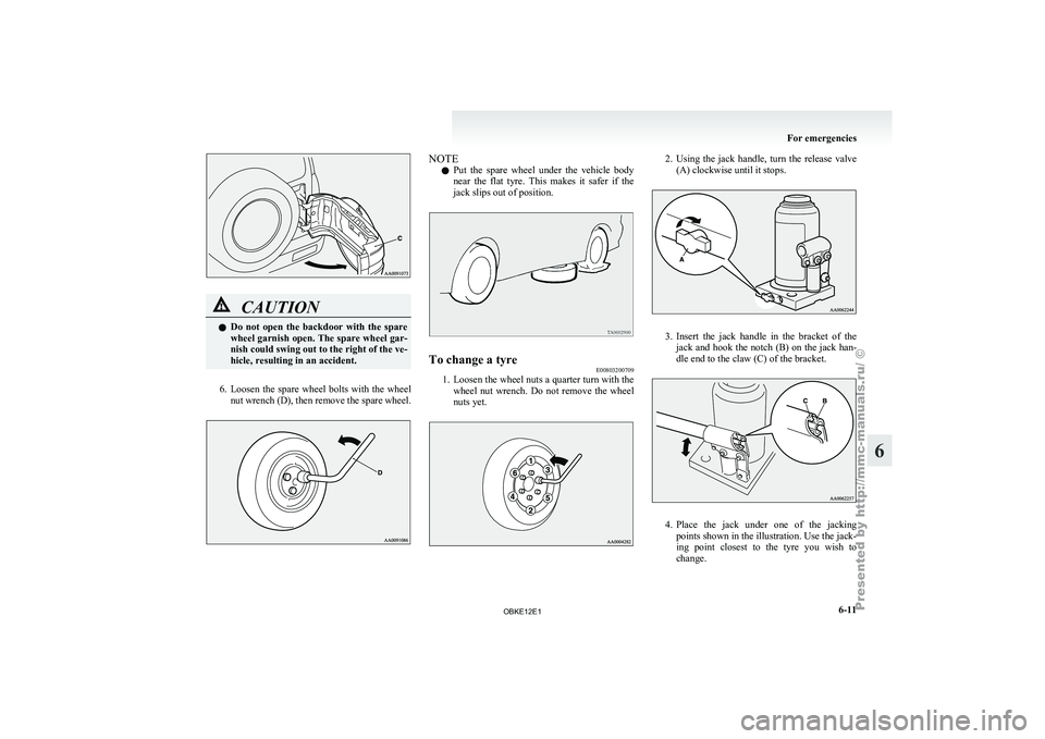
CAUTION
l
Do not
open the backdoor with the spare
wheel garnish open. The spare wheel gar-
nish could swing out to the right of the ve-
hicle, resulting in an accident.
6. Loosen the spare wheel bolts with the wheel
nut wrench
(D), then remove the spare wheel. NOTE
l Put
the spare
wheel under the vehicle body
near the flat tyre. This makes it safer if the
jack slips out of position. To change a tyre
E00803200709
1. Loosen the wheel nuts a quarter turn with the
wheel nut
wrench. Do not remove the wheel
nuts yet. 2. Using the jack handle, turn the release valve
(A) clockwise until it stops. 3. Insert the jack handle in the bracket of the
jack and
hook the notch (B) on the jack han-
dle end to the claw (C) of the bracket. 4. Place
the jack under one of the jacking
points shown in the illustration. Use the jack-
ing point
closest to the tyre you wish to
change. For emergencies
6-11 6
OBKE12E1
Page 293 of 377
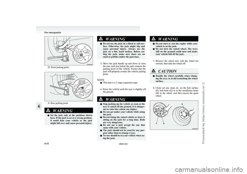
D- Front jacking point
E- Rear jacking point
WARNING
l Set the
jack only at the positions shown
here. If the jack is set at a wrong position,
it could dent your vehicle or the jack
might fall over and cause personal injury. WARNING
l Do not use
the jack on a tilted or soft sur-
face. Otherwise, the jack might slip and
cause personal injury. Always use the
jack on a flat, hard surface. Before set-
ting the jack, make sure there are no
sand or pebbles under the jack base.
5. Move the jack handle up and down to raise
the ram
until just before the jack contacts the
jacking point of the vehicle. Ensure that the
jack will properly contact the vehicle jacking
point.
NOTE l This jack is a 3 stage expansion type.
6. Raise the vehicle until the tyre is slightly off the ground. WARNING
l Stop jacking
up
the vehicle as soon as the
tyre is raised off the ground. It is danger-
ous to raise the vehicle any higher.
l Do not get under your vehicle while using
the jack.
l Do not bump the raised vehicle or leave it
sitting on the jack for a long time. Both
are very dangerous.
l Do not use a jack except the one that
came with your vehicle.
l The jack should not be used for any pur-
pose other than to change a tyre.
l No one should be in your vehicle when us-
ing the jack. WARNING
l Do not start
or run the engine while your
vehicle is on the jack.
l Do not turn the raised wheel. The tyres
still on the ground could turn and make
your vehicle fall off the jack.
7. Remove the wheel nuts with the wheel nut
wrench, then take the wheel off. CAUTION
l
Handle the
wheel
carefully when chang-
ing the tyre, to avoid scratching the wheel
surface.
8. Clean out any mud, etc. on the hub surface
(F), hub
bolts (G) or in the installation holes
(H) in the wheel, and then mount the spare
wheel. For emergencies
6-12
6
OBKE12E1
Page 294 of 377
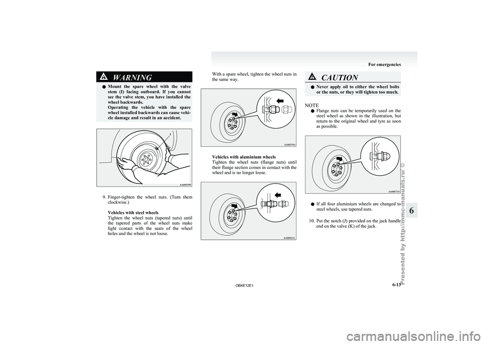
WARNING
l Mount the spare wheel with the valve
stem (I) facing outboard. If you cannot
see the valve stem, you have installed the
wheel backwards.
Operating the vehicle with the spare
wheel installed backwards can cause vehi-
cle damage and result in an accident. 9. Finger-tighten the
wheel
nuts. (Turn them
clockwise.)
Vehicles with steel wheels
Tighten the wheel nuts (tapered nuts) until
the tapered parts of the wheel nuts make
light contact with the seats of the wheel
holes and the wheel is not loose. With a spare wheel, tighten the wheel nuts in
the same way.
Vehicles with aluminium wheels
Tighten the
wheel
nuts (flange nuts) until
their flange section comes in contact with the
wheel and is no longer loose. CAUTION
l
Never apply oil
to either the wheel bolts
or the nuts, or they will tighten too much.
NOTE l Flange
nuts can
be temporarily used on the
steel wheel as shown in the illustration, but
return to the original wheel and tyre as soon
as possible. l
If all
four
aluminium wheels are changed to
steel wheels, use tapered nuts.
10. Put the notch (J) provided on the jack handle end on the valve (K) of the jack. For emergencies
6-13 6
OBKE12E1
Page 296 of 377
CAUTION
l
After
changing
the tyre and driving the ve-
hicle about 1,000 km (620 miles), retight-
en the wheel nuts to make sure that they
have not come loose.
l If the steering wheel vibrates when driv-
ing after changing the tyre, we recom-
mend you to have the tyres checked for
balance.
l Do not mix one type of tyre with another
or use a different size from the one listed.
This would cause early wear and poor han-
dling.
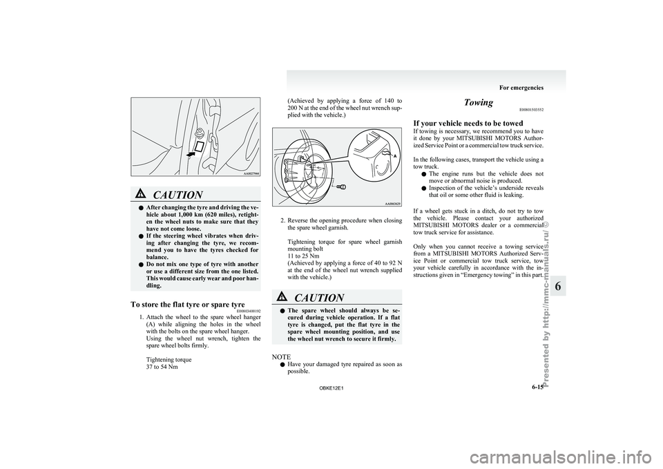
To store the flat tyre or spare tyre E00803400192
1. Attach the wheel to the spare wheel hanger
(A) while
aligning the holes in the wheel
with the bolts on the spare wheel hanger.
Using the wheel nut wrench, tighten the
spare wheel bolts firmly.
Tightening torque
37 to 54 Nm (Achieved by applying a force of 140 to
200 N
at the end of the wheel nut wrench sup-
plied with the vehicle.) 2. Reverse the opening procedure when closing
the spare wheel garnish.
Tightening torque
for spare wheel garnish
mounting bolt
11 to 25 Nm
(Achieved by applying a force of 40 to 92 N
at the end of the wheel nut wrench supplied
with the vehicle.) CAUTION
l
The spare
wheel
should always be se-
cured during vehicle operation. If a flat
tyre is changed, put the flat tyre in the
spare wheel mounting position, and use
the wheel nut wrench to secure it firmly.
NOTE l Have
your damaged
tyre repaired as soon as
possible. Towing
E00801503552
If your vehicle needs to be towed
If towing
is
necessary, we recommend you to have
it done by your MITSUBISHI MOTORS Author-
ized Service Point or a commercial tow truck service.
In the following cases, transport the vehicle using a
tow truck.
l The engine runs but the vehicle does not
move or abnormal noise is produced.
l Inspection of the vehicle’s underside reveals
that oil or some other fluid is leaking.
If a wheel gets stuck in a ditch, do not try to tow
the vehicle. Please contact your authorized
MITSUBISHI MOTORS dealer or a commercial
tow truck service for assistance.
Only when you cannot receive a towing service
from a MITSUBISHI MOTORS Authorized Serv-
ice Point or commercial tow truck service, tow
your vehicle carefully in accordance with the in-
structions given in “Emergency towing” in this part.
For emergencies
6-15 6
OBKE12E1