ECU MITSUBISHI SHOGUN 2017 (in English) Owner's Guide
[x] Cancel search | Manufacturer: MITSUBISHI, Model Year: 2017, Model line: SHOGUN, Model: MITSUBISHI SHOGUN 2017Pages: 394, PDF Size: 19 MB
Page 74 of 394

Installing a child restraint sys-tem to the lower anchorage (ISOFIX child restraint mount-ings) and tether anchorage*
E00408901980
Lower anchorage location
Your vehicle’s rear seat (3-door models)/ second seat (5-door models) is fitted with
lower anchorages for attaching a child re- straint system with ISOFIX mountings.
Tether anchorage locations
There are 2 attachment points on the floor, located behind the rear seat (3-door models)/
second seat (5-door models). These are for securing a child restraint system tether strap to both of the 2 rear (3-door models)/second (5-door models) seating positions in your ve-
hicle.
WARNINGl Child restraint anchorages are designed
to withstand only those loads imposed by
correctly fitted child restraints. Under no circumstances are they to be used for adult seat belts, harnesses, or for attach-
ing other items or equipment to the vehi- cle.Child restraint system with
ISOFIX mountings
The child restraint system is designed only
for seats that incorporate lower anchorages.
Retain the child restraint system using the lower anchorages.
It is not necessary to retain the child restraint
system using the vehicle’s seat belts.
A: Child restraint System connectors
To install
1. Remove any foreign material in or
around the connectors and ensure the ve-
hicle seat belt is in its normal storage po-
sition.
2. Remove the head restraint from the loca-
tion in which you wish to install a child
restraint.
Refer to “Head restraints” on page 4-12.
Child restraint
4-34OVWX17E1Seat and seat belts4
Page 75 of 394

3.Push the child restraint system’s connec-
tors (A) into the slits (B) in accordance with the instructions provided by the
child restrain system’s manufacturer.
A- Connector B- Slit
C- Vehicle seatback
D- Vehicle seat cushion E- Lower anchorage
If your child restraint system requires the
use of a tether strap, fasten the tether strap in accordance with steps 4 through 5.
4. Open the cover from the tether anchor-
age installation point by pulling it back
with your hand as illustrated.
5. Latch the top tether strap hook (F) of the
child restraint system to the tether an- chorage bracket (G) and tighten the top
tether strap so that it is securely fas- tened.
WARNINGl Do not latch the top tether strap hook to
any place, for example the luggage hook (H), other than the tether anchorage
bracket (I), or the child restraint system could not be fastened securely, resulting
in serious injury in the event of a collision.
6. Push and pull the child restraint system
in all directions to be sure it is firmly se- cured.
To remove
Remove the child restraint in accordance
with the instructions provided by the child re-
straint system’s manufacturer.
Installing a child restraint sys-
tem to a 3-point type seat belt
E00408701887
3-door models5-door models
Installation:
1. Put a child restraint system on the seat in
which you wish to install it, and remove
the head restraint from the seat.
Refer to “Head restraints” on page 4-12.
Child restraint
4-35OVWX17E1Seat and seat belts4
Page 76 of 394

2.Fasten the seat belt to secure the child
restraint system. Make sure you hear a “click” when you insert the latch plate in
the buckle.
3. Remove all slack by using the locking
clip.
4. Push and pull the child restraint in all di-
rections to be sure it is secure.WARNINGl For some types of child restraint, the lock-
ing clip (A) should be used to help avoid personal injury during a collision or sud-den manoeuvre.
It must be fitted and used in accordance
with the child restraint manufacturer’s instructions.
The locking clip must be removed when the child restraint is removed.Seat belt inspection
E00406301690
Check the belts for cuts, worn or frayed web- bing and for cracked or deformed metallic
parts. Replace the belt assembly if it is defec-
tive.WARNINGl We recommend you to have all seat belt
assemblies including retractors and at-
taching hardware inspected after any col- lision. We recommend that seat belt as-
semblies in use during a collision be re- placed unless the collision was minor and
the belts show no damage and continue to operate properly.
l Do not attempt to repair or replace any
part of the seat belt assemblies; we recom-
mend you to have this work done by a MITSUBISHI MOTORS Authorized
Service Point. Incorrect repair or replace-
ment could reduce the effectiveness of the
belts and could result in serious injury in the event of a collision.
l Once the pretensioner has been activated,
it cannot be re-used.
It must be replaced together with the re-
tractor.WARNINGl Do not insert any foreign objects (pieces
of plastic, paper clips, buttons, etc.) in the
buckle or retractor mechanism. In addi- tion, do not modify, remove or install the
seat belt. Otherwise, the seat belt may not be able to provide adequate protection in a collision or other situation.
l A dirty belt should be cleaned with neu-
tral detergent in warm water. After rins-
ing in water, let it dry in the shade. Do not
attempt to bleach or re-dye the belts be-
cause this will affect their characteristics.
Supplemental restraint
system (SRS) - airbag E00407203397
The information written in this Supplemental
Restraint System (SRS) section contains im- portant points concerning the driver, front
passenger, side and curtain airbags.
Seat belt inspection
4-36OVWX17E1Seat and seat belts4
Page 141 of 394
Your driving ability can be seriously im-
paired even with blood alcohol levels far be- low the legal minimum. If you have beendrinking, don’t drive. Ride with a designated
non-drinking driver, call a cab or a friend, or
use public transportation. Drinking coffee or taking a cold shower will not make you so-ber.
Similarly, prescription and nonprescription
drugs affect your alertness, perception and re- action time. Consult with your doctor or
pharmacist before driving while under the in- fluence of any of these medications.WARNINGl NEVER DRINK AND DRIVE.
Your perceptions are less accurate, your reflexes are slower and your judgment is
impaired.Safe driving techniques
E00600300488
Driving safety and protection against injury
cannot be fully ensured. However, we recom- mend that you pay extra attention to the fol-
lowing:
Seat belts
Before starting the vehicle, make sure that
you and your passengers have fastened your seat belts.
Floor mats
WARNINGl Keep floor mats clear of the pedals by
correctly laying floor mats that are suita-
ble for the vehicle.
To prevent the floor mats from slipping out of position, securely retain them usingthe hook etc.
Note that laying a floor mat over a pedal
or laying one floor mat on top of another can obstruct pedal operation and lead to a
serious accident.Carrying children in the vehi-
cle
l Never leave your vehicle unattended
with the key in the ignition and children
inside the vehicle. Children may play with the driving controls and this could
lead to an accident.
l Make sure that infants and small chil-
dren are properly restrained in accord-
ance with the laws and regulations, and for maximum protection in case of an
accident.
l Prevent children from playing in the lug-
gage compartment. It is quite dangerousto allow them to play there while the ve-
hicle is moving.
Safe driving techniques
6-03OVWX17E1Starting and driving6
Page 144 of 394
Apply the parking brake and place the selec-tor lever into the “P” (PARK) position.
If necessary, apply chocks to wheels.NOTEl Be sure to apply the parking brake before
moving the selector lever to the “P” (PARK)
position. If you move the selector lever to the “P” (Park) position before applying the
parking brake, it may be difficult to disen-
gage the selector lever from the “P” (Park) position when next you drive the vehicle, re-quiring application of a strong force to the
selector lever to move from the “P” (Park) position.
Parking with the engine run-
ning
Never leave the engine running while you
take a short sleep/rest, or you open or close a gate or garage door, etc. Also, never leave the
engine running in a closed or poorly ventila-
ted place.
WARNINGl Leaving the engine running risks injury
or death from accidentally moving the se- lector lever or the accumulation of toxic
exhaust fumes in the passenger compart-
ment.Where you parkWARNINGl Do not park your vehicle in areas where
combustible materials such as dry grass
or leaves can come in contact with a hot exhaust, since a fire could occur.
When leaving the vehicle
Always remove the key from the ignition
switch and lock all doors (including the back-
door) when leaving the vehicle unattended. Always try to park your vehicle in a well lit area.
Steering wheel height
adjustment E00600700222
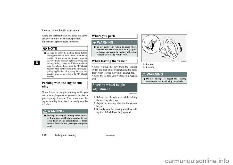
1.Release the tilt lock lever while holding
the steering wheel up.
2. Adjust the steering wheel to the desired
height.
3. Securely lock the steering wheel by pull-
ing the tilt lock lever fully upward.
A- Locked
B- Release
WARNINGl Do not attempt to adjust the steering
wheel while you are driving the vehicle.
Steering wheel height adjustment
6-06OVWX17E1Starting and driving6
Page 156 of 394
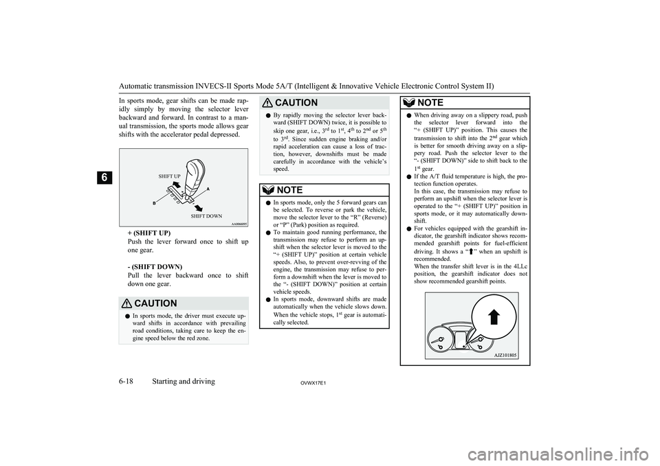
In sports mode, gear shifts can be made rap-idly simply by moving the selector leverbackward and forward. In contrast to a man-
ual transmission, the sports mode allows gear shifts with the accelerator pedal depressed.SHIFT UPSHIFT DOWN
+ (SHIFT UP)
Push the lever forward once to shift up
one gear.
- (SHIFT DOWN)
Pull the lever backward once to shift
down one gear.
CAUTIONl In sports mode, the driver must execute up-
ward shifts in accordance with prevailingroad conditions, taking care to keep the en-
gine speed below the red zone.CAUTIONl By rapidly moving the selector lever back-
ward (SHIFT DOWN) twice, it is possible to
skip one gear, i.e., 3 rd
to 1 st
, 4 th
to 2 nd
or 5 th
to 3 rd
. Since sudden engine braking and/or
rapid acceleration can cause a loss of trac-
tion, however, downshifts must be made carefully in accordance with the vehicle’s
speed.NOTEl In sports mode, only the 5 forward gears can
be selected. To reverse or park the vehicle, move the selector lever to the “R” (Reverse)
or “P” (Park) position as required.
l To maintain good running performance, the
transmission may refuse to perform an up- shift when the selector lever is moved to the
“+ (SHIFT UP)” position at certain vehicle speeds. Also, to prevent over-revving of the
engine, the transmission may refuse to per- form a downshift when the lever is moved to
the “- (SHIFT DOWN)” position at certain vehicle speeds.
l In sports mode, downward shifts are made
automatically when the vehicle slows down.
When the vehicle stops, 1st
gear is automati-
cally selected.NOTEl When driving away on a slippery road, push
the selector lever forward into the“+ (SHIFT UP)” position. This causes the
transmission to shift into the 2nd
gear which
is better for smooth driving away on a slip-
pery road. Push the selector lever to the
“- (SHIFT DOWN)” side to shift back to the
1 st
gear.
l If the
A/T fluid temperature is high, the pro-
tection function operates.
In this case, the transmission may refuse to perform an upshift when the selector lever is
operated to the “+ (SHIFT UP)” position in
sports mode, or it may automatically down- shift.
l For vehicles equipped with the gearshift in-
dicator, the gearshift indicator shows recom- mended gearshift points for fuel-efficient
driving. It shows a “
” when an upshift is
recommended.
When the transfer shift lever is in the 4LLc
position, the gearshift indicator does not show recommended gearshift points.
Automatic transmission INVECS-II Sports Mode 5A/T (Intelligent & Innovative Vehicle Electronic Control System II)
6-18OVWX17E1Starting and driving6
Page 170 of 394

NOTElBefore attempting to drive up the slope,
walk it up to confirm that the vehicle canhandle the grade.
Descending sharp grades
Set the transfer shift lever to the “4LLc” po-
sition, use the engine brake (downshifting)
and descend slowly.
WARNINGl Avoid snaking down a sharp grade. De-
scend the grade as straight as possible.NOTEl When descending a sharp grade, if the
brakes are applied suddenly because of an
obstacle encountered, control of the vehicle
could be lost. Before descending the slope,
walk it down and confirm the path.
l Before descending a grade, it is necessary to
choose the appropriate gear. Avoid changing
gears or depressing the clutch while de- scending the grade.NOTEl MITSUBISHI
MOTORS is not responsible
to the operator for any damage or injury caused or liability incurred by improper and negligent operation of a vehicle. All techni-
ques of vehicle operation described herein depend on the skill and experience of the op- erator and other participating parties and any
deviation from the recommended operation
instructions above is at their own risk.
Turning sharp corners
When turning a sharp corner in the “4HLc”
or “4LLc” position at low speed, a slight dif-
ference in steering may be experienced simi- lar to as if the brakes were applied. This is
called tight corner braking and results from each of the 4 tyres being at a different dis-tance from the corner.
The phenomenon is peculiar to 4-wheel drive vehicles. If this occurs, either straighten the steering wheel, or change to rear-wheel drive.
Crossing a stream
4-wheel drive vehicles are not necessarily waterproof. If the electrical circuits become
wet, further operation of the vehicle will be impossible; therefore, avoid crossing streams
unless absolutely necessary. If crossing a
stream is unavoidable, use the following pro- cedure:
1. Check depths of a stream and geographi-
cal features before attempting to cross a
stream and ford the stream where the
water is as shallow as practicable.
2. Cross at a place where the water is less
than 70 cm deep.
3. Set the transfer shift lever to the “4LLc”
position.
4. Drive slowly at a speed of approximate-
ly 5 km/h (3 mph) to avoid splashing too
much water.CAUTIONl Do not attempt to cross a stream at a place
where the water is more than 70 cm deep.
l Cross a stream temporarily for emergencies
and avoid doing so for a long period of time.
l After crossing a stream, apply the brakes to
be sure they are functioning properly. If the
brakes are wet and not functioning properly,
dry them out by driving slowly while lightly
depressing the brake pedal.
Inspect each part of the vehicle carefully.NOTEl Because the inside of the vehicle is flooded
with water when crossing at a place where
the water is more than 50 cm deep, we rec- ommend you to have your vehicle inspected.
4-wheel drive operation
6-32OVWX17E1Starting and driving6
Page 174 of 394

lOn vehicles with the rear differential
lock, the active stability & traction con- trol (ASTC) and anti-lock brake system
(ABS) functions are suspended while the
rear differential lock is activated. ASTC indication lamp, Active Stability Controlfunction OFF indication lamp, ABS
warning lamp and brake warning lamp are illuminated while these functions are
suspended. It does not indicate a prob- lem. When the rear differential lock is
disengaged, these lamps go out and function again.
Refer to “Brake warning lamp” on page
5-10 , “ABS warning lamp” on page
6-38 , “ASTC indication lamp” on page
6-40 , “Active stability control function
OFF indication lamp” on page 6-42.
When brakes are wet
Check the brake system while driving at a
low speed immediately after starting, espe- cially when the brakes are wet, to confirmthey work normally.
A film of water can be formed on the brake
discs and prevent normal braking after driv-
ing in heavy rain or through large puddles, or after the vehicle is washed. If this occurs, dry
the brakes out by driving slowly while lightly depressing the brake pedal.
When driving downhill
It is important to take advantage of the en-
gine braking by shifting to a lower shift posi- tion while driving on steep downhill roads in order to prevent the brakes from overheating.
WARNINGl Do not leave any objects near the brake
pedal or let a floor mat slide under it; do- ing so could prevent the full pedal strokethat would be necessary in an emergency.
Make sure that the pedal can be operated freely at all times. Make sure the floor mat is securely held in place.
Brake pads
l Avoid hard braking situations.
New brakes need to be broken-in by
moderate use for the first 200 km (125 miles).
l The disc brakes are provided with a
warning device which emits a shrieking
metallic sound while braking if the brake pads have reached their wear limit.
If you hear this sound, have the brake pads replaced immediately.
WARNINGl Driving with worn brake pads will make
it harder to stop, and can cause an acci-
dent.Brake assist system
E00627001852
The brake assist system is a device assistingdrivers who cannot depress the brake pedalfirmly when it is necessary to do so (such as
in emergency stop situations) and provides
greater braking force.
If the brake pedal is depressed suddenly, the brakes will be applied with more force thanusual.
CAUTIONl The brake assist system is not a device de-
signed to exercise braking force greater than its capacity. Make sure to always keep a suf-
ficient distance between your vehicle and a
vehicle in front of you without relying too much on the brake assist system.
Brake assist system
6-36OVWX17E1Starting and driving6
Page 186 of 394
WARNINGlAlthough the set speed driving will be de-
activated when shifting to the “N” (NEU-
TRAL) position, never move the selector lever to the “N” (NEUTRAL) position
while driving.
You would have no engine braking and
could cause a serious accident.
Also, the set speed driving may be deactiva-
ted as follows:
l When the engine speed rises and ap-
proaches the tachometer’s red zone (the red-coloured part of the tachometer di-
al).
CAUTIONl When the set speed driving is deactivated
automatically in any situation other thanthose listed above, there may be a system
malfunction.
Press the “ON-OFF” switch to turn off the cruise control and have your vehicle inspec- ted by a MITSUBISHI MOTORS Author-
ized Service Point.To resume the set speed
E00609800460
If the set speed driving is deactivated by the
condition described in “To deactivate” on
page 6-47, you can resume the previously set
speed by pressing the “ACC RES” switch (C)
while driving at a speed of about 40 km/h (25 mph) or higher.
Under either of the following conditions,however, using the switch does not allow you
to resume the previously set speed. In these
situations, repeat the speed setting procedure:
l The “ON OFF” switch is pressed.
l The ignition switch is turned OFF.
l “CRUISE” indication lamp is turned
OFF.
Tyre pressure monitoring
system (TPMS)* E00637100077
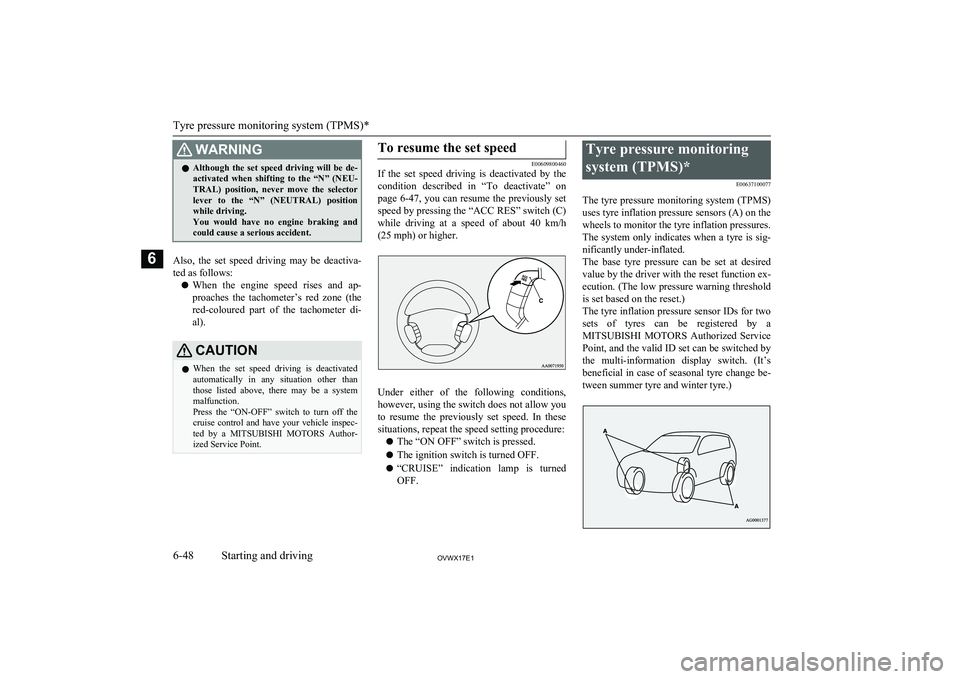
The tyre pressure monitoring system (TPMS)
uses tyre inflation pressure sensors (A) on the wheels to monitor the tyre inflation pressures.
The system only indicates when a tyre is sig-
nificantly under-inflated.
The base tyre pressure can be set at desired value by the driver with the reset function ex-
ecution. (The low pressure warning threshold is set based on the reset.)
The tyre inflation pressure sensor IDs for two sets of tyres can be registered by aMITSUBISHI MOTORS Authorized Service
Point, and the valid ID set can be switched by the multi-information display switch. (It’s
beneficial in case of seasonal tyre change be-
tween summer tyre and winter tyre.)
Tyre pressure monitoring system (TPMS)*
6-48OVWX17E1Starting and driving6
Page 189 of 394

WARNINGlIf the warning lamp illuminates while you
are driving, avoid hard braking, sharp steering manoeuvres and high speeds.
Driving with an under-inflated tyre ad-
versely affects vehicle performance and
can result in an accident.CAUTIONl The warning lamp may not illuminate imme-
diately in the event of a tyre blowout or rap-
id leak.NOTEl To avoid the risk of damage to the tyre infla-
tion pressure sensors, have any punctured
tyre repaired by a MITSUBISHI MOTORS
Authorized Service Point. If the tyre repair is
not done by a MITSUBISHI MOTORS Au-
thorized Service Point, damage to the tyre
inflation pressure sensor is not covered by your warranty.
l Do not use an aerosol puncture-repair spray
on any tyre.
Such a spray could damage the tyre inflation
pressure sensors.
Have any puncture repaired by a MITSUBISHI MOTORS Authorized Serv-
ice Point.The tyre pressure monitoring system (TPMS)
may not work normally in the following cir-
cumstances:
l A wireless facility or device using the
same frequency is near the vehicle.
l Snow or ice is stuck inside the fenders
and/or on the wheels.
l The tyre inflation pressure sensor’s bat-
tery is dead.
l Wheels other than
MITSUBISHI
MOTORS GENUINE wheels are being
used.
l Wheels that are not fitted with tyre infla-
tion pressure sensors are being used.
l Wheels whose ID codes are not memo-
rized by the vehicle are used.
l A window tint that affects the radio
wave signals is installed.NOTEl Tyre inflation pressures vary with the ambi-
ent temperature. If the vehicle is subjected to large variations in ambient temperature, the tyre inflation pressures may be underinflated
(causing the warning lamp come on) when the ambient temperature is relatively low. If
the warning lamp comes on, adjust the tyre inflation pressure.Whenever the tyres and wheels
are replaced with new ones
E00637400025
If new wheels with new tyre inflation pres-
sure sensors are installed, their ID codes must be programmed into the tyre pressure moni- toring system. Have tyre and wheel replace-
ment performed by a MITSUBISHI
MOTORS Authorized Service Point to avoid
the risk of damaging the tyre inflation pres- sure sensors. If the wheel replacement is not
done by a MITSUBISHI MOTORS Author-
ized Service Point, it is not covered by your warranty.
CAUTIONl The use of non-genuine wheels will prevent
the proper fit of the tyre inflation pressure sensors, resulting air leakage or damage of
the sensors.Reset of low tyre pressure
warning threshold
E00637500055
The threshold is set based on the tyre pres- sure which the reset function is executed by
following procedure. 1. Transit the display by the button (A) un-
til the tyre pressure monitoring system
(TPMS) SET indicator is displayed.
Tyre pressure monitoring system (TPMS)*
6-51OVWX17E1Starting and driving6