check oil MITSUBISHI SPYDER 1990 Service Repair Manual
[x] Cancel search | Manufacturer: MITSUBISHI, Model Year: 1990, Model line: SPYDER, Model: MITSUBISHI SPYDER 1990Pages: 2103, PDF Size: 68.98 MB
Page 1042 of 2103
![MITSUBISHI SPYDER 1990 Service Repair Manual AUTOMATIC TRANSAXLE
ENGINE (TURBO) AND ENGINE>
INSPECTION PROCEDURE 3
l Does not move forward
[Comment] Abnormal line pressure
When the engine is idling, the does not move for](/img/19/57345/w960_57345-1041.png "MITSUBISHI SPYDER 1990 Service Repair Manual AUTOMATIC TRANSAXLE
ENGINE (TURBO) AND ENGINE>
INSPECTION PROCEDURE 3
l Does not move forward
[Comment] Abnormal line pressure
When the engine is idling, the does not move for")
AUTOMATIC TRANSAXLE
ENGINE (TURBO) AND ENGINE>
INSPECTION PROCEDURE 3
l Does not move forward
[Comment] Abnormal line pressure
When the engine is idling, the does not move forward even if the lever is l
Malfunction of rear shifted from to 2 or range. In such cases, the cause is probably abnorm al line pressure,l Malfunction of one-way or a defective rear or one-way clutch.
l Malfunction of body
Refer to Automatic Transaxle Overhaul’
NG
Vehicle usually starts off but forwardmovement
sometimes becomes in or 2.
Yes
Hydraulic pressure test
(Refer to
l Check the rear clutch pressure
when shifting from to range.
S t a n d a r d
psi)
OK
Rear clutch system check lRemove the oil pan and valve body.l Pistons should operate and pres-
sure should also be maintained
when air is blown through the rear
clutch oil holes in the transaxle
case.
OK
body disassembly, cleaningand reassembly Pay particular attention to loos-
ening of bolts, and to damage,
chipping or slippage of O-rings,
valve intermediate plate andbody.lIf it is considered that the dam-age or chipping cannot be re-
paired, replace the valve body
assembly.
NG
moves forward in range.
Yes
Replace the one-way clutch.
Rear clutch check lCheck for burning of the facing,
defective piston seal rings and
interference between the end
plate and retainer.
TSB Revision
Page 1043 of 2103
![MITSUBISHI SPYDER 1990 Service Repair Manual AUTOMATIC TRANSAXLE
ENGINE (TURBO) AND ENGINE> Troubleshooting
INSPECTION PROCEDURE 4l Does not back-up
[Comment]When the engine is idling, the vehicle does not bac k-up even if](/img/19/57345/w960_57345-1042.png "MITSUBISHI SPYDER 1990 Service Repair Manual AUTOMATIC TRANSAXLE
ENGINE (TURBO) AND ENGINE> Troubleshooting
INSPECTION PROCEDURE 4l Does not back-up
[Comment]When the engine is idling, the vehicle does not bac k-up even if")
AUTOMATIC TRANSAXLE
ENGINE (TURBO) AND ENGINE> Troubleshooting
INSPECTION PROCEDURE 4l Does not back-up
[Comment]When the engine is idling, the vehicle does not bac k-up even if the lever is shifted
from to range. In such cases, the cause is abnormal pressure in the low reverse
brake or front clutch, or a defective low reverse b rake or front clutch.l
Abnormal low reverse brake pressurel Abnormalfront pressurel Malfunction of front l of low reverse of valve
Hydraulic pressure test
(Refer to
lMeasure the front clutch pressure
in range at Standard value: 2,240 (233-319 psi)
NG
Refer to Automatic Transaxle Overhaul
Hydraulic pressure test
(Refer to
l Measure the low reverse brakepressure in range at 2,500 Standard value: (233-319 psi) Front
lRemove the oil pan and body.l
Pistons operate and pres-
sure should also be maintained
when air is blown through the front oil holes in the c a s e .NGOK
NG. Front clutch and low reverse Low reverse brake system check
lRemove the oil pan and valvebody.l Pistons operate and
pressure should also be
maintained when air is blown
through the low reverse brake oil holes in the transaxle case.
OK
Valve body disassembly, and reassembly Pay attention to loos-
ening of bolts, and to damage,
chipping or
of O-rings, intermediate plate andbody.if it is considered that the dam-age or chipping cannot be re- paired, replace the valve body
assembly.
Probable cause
checklCheck for burning of the facing,defective piston seal rings andinterference between the end and retainer. O K
TSB Revision
Page 1044 of 2103
![MITSUBISHI SPYDER 1990 Service Repair Manual AUTOMATIC TRANSAXLE
ENGINE (TURBO) AND ENGINE> ,
INSPECTION PROCEDURE 5 .
lDoes not move (forward or reverse)
[Comment]
P r o b a b l e c a u s e ‘
When the engine is idling, the ve](/img/19/57345/w960_57345-1043.png "MITSUBISHI SPYDER 1990 Service Repair Manual AUTOMATIC TRANSAXLE
ENGINE (TURBO) AND ENGINE> ,
INSPECTION PROCEDURE 5 .
lDoes not move (forward or reverse)
[Comment]
P r o b a b l e c a u s e ‘
When the engine is idling, the ve")
AUTOMATIC TRANSAXLE
ENGINE (TURBO) AND ENGINE> ,
INSPECTION PROCEDURE 5 .
lDoes not move (forward or reverse)
[Comment]
P r o b a b l e c a u s e ‘
When the engine is idling, the vehicle does not mov e forward or in reverse even if the selectorl
Abnormal reducing pressure
l
lever is shifted from
to 2, or range. In such cases, the cause is probably abnorm alMalfunction of power train
l
reducing pressure, or a defective oil pump or power train.Malfunction of oil pump
l ‘ o f v a l v e b o d y
Refer to Automatic Transaxle Overhaul
O K
Hydraulic pressure test (Refer to .
l Measure the reducing pressure in range while the
engine is idling.
Standard value:
psi)
NG
Reducing pressure OK
Power train check lDisassemble the transaxle, check the condition of t he
and repair or replace if necessary.
Check to be sure that there are no abnormalities su ch
lIf it is considered that the damage or chipping can
not
be repaired, replace the valve body assembly.If there is an abnormality, replace the oil pump as sembly.
INSPECTION PROCEDURE 6
l Engine stalling during shifting
cause
[Comment] Malfunction of engine systemWhen the engine is idling, the engine stalls when t he selector lever is shifted from to l
2, or range. In such cases, the cause is probably a defe ctive engine system or damper lMalfunction of torque solenoid
clutch control solenoid valve. Malfunction of body l
Malfunction of torque converter
Refer to Automatic Transaxle Overhaul
Enaine check .
l the control system, ignition system, fuel system a nd main engine system, and confirm that everything is l If there is an abnormality, repair or replace the e ngine system.
After completion
Solenoid valve connector check
l Check to be sure that there is no water in the conn ector.
l Check to be sure that none of the terminals are sho
rted to each other.
After completion
Torque converter clutch solenoid check l Check to be sure that the valve is not sticking due to foreign materials packed inside solenoid.
l If there is an abnormality, replace the solenoid as sembly.
After completion
Transaxle cooling system check l Check for plugged cooler lines.
l Check for plugged oil cooler.
After completion
Valve body disassembly, cleaning and reassembly
l
l Pay particular attention to loosening of bolts, and
to damage, chipping or slippage of O-rings, valve intermediate plate and body.
If it is considered that the damage or chipping can not be repaired, replace the valve body assembly.
After completion
Torque converter check l Check to be sure that there is no sticking due to s eparation from the damper clutch.
l If there is an abnormality, replace the torque conv erter assembly.
Revision
Page 1045 of 2103
![MITSUBISHI SPYDER 1990 Service Repair Manual AUTOMATIC TRANSAXLE
ENGINE (TURBO) AND ENGINE> Troubleshooting
INSPECTION PROCEDURE 7
lShocks when shifting from to and long lag timeProbable cause
[Comment]l Malfunction of rear](/img/19/57345/w960_57345-1044.png "MITSUBISHI SPYDER 1990 Service Repair Manual AUTOMATIC TRANSAXLE
ENGINE (TURBO) AND ENGINE> Troubleshooting
INSPECTION PROCEDURE 7
lShocks when shifting from to and long lag timeProbable cause
[Comment]l Malfunction of rear")
AUTOMATIC TRANSAXLE
ENGINE (TURBO) AND ENGINE> Troubleshooting
INSPECTION PROCEDURE 7
lShocks when shifting from to and long lag timeProbable cause
[Comment]l Malfunction of rear clutchWhen the engine is idling, abnormal shocks or a lag time of 2 seconds or more occur whenMalfunction of valve bodythe selector lever is shifted from to range. In such cases, the cause is probably a defe ctiveMalfunction closed switch’
rear clutch or valve body
.
Refer to Automatic Transaxle‘ Overhaul
When does the shock occur? When shifting from
to
Rear clutch system check l Remove the transaxle, oil pan and valve body. When starting offShocks sometimes occur
Pistons should and should also be maintained when’ air is blown through the rear clut
ch
oil holes in the transaxle case.
NG
Rear clutch check l Check for burning of the facing,
defective piston seal rings and
interference between the end plateand retainer.
Valve body disassembly, cleaning andreassembly
of bolts, and to damage, chipping
or slippage of O-rings, valve inter-
mediate plate and body.
lIf it is considered that the damage
or cannot be repaired, place’ the-valve body assembly.
OK
Yes
Closed switch check l Check the throttle positionswitch system. according to Eon procedures 17. to
TSB Revision
Page 1046 of 2103
![MITSUBISHI SPYDER 1990 Service Repair Manual AUTOMATIC TRANSAXLE ,
E N G I N E ( T U R B O ) A N D E N G I N E >
INSPECTION PROCEDURE 8
lShocks when shifting from to and long lag time
[Comment]When the engine is idling, abnor](/img/19/57345/w960_57345-1045.png "MITSUBISHI SPYDER 1990 Service Repair Manual AUTOMATIC TRANSAXLE ,
E N G I N E ( T U R B O ) A N D E N G I N E >
INSPECTION PROCEDURE 8
lShocks when shifting from to and long lag time
[Comment]When the engine is idling, abnor")
AUTOMATIC TRANSAXLE ,
E N G I N E ( T U R B O ) A N D E N G I N E >
INSPECTION PROCEDURE 8
lShocks when shifting from to and long lag time
[Comment]When the engine is idling, abnormal shocks or a lag time of 2 seconds or more occurs when
the selector lever is shifted from to range.In such cases, the cause is probably abnormallow reverse brake or front clutch pressure, or a de fective low reverse brake or front clutch.
, When starting off
Probable cause
Abnormal front clutch pressurel Abnormal low reverse brake l Malfunction of front clutchl Malfunction of low reverse brake M a l f u n c t i o n o f v a l v e
Refer to Automatic Transaxle Overhaul
I When does the shock
When from to
pressure test, NG
(defer to Measure the front clutch pressure
in range at 2,500 Standard value:1,640 2,240
OK
Hydraulic pressure test
(Refer to
l Measure the low reverse brakepressure in range at 2,500 Standard value:1,640
NG
lRemove the transaxle, oil pan and
l Pistons should operate and
when air is blown throuah the lowreverse brake oil holes trans-axle case.I
OK
Front clutch system check Remove the transaxle, oil pan and
valve body.
Pistons should operate and pres- sure should also be maintained
when air is blown through the frontclutch oil holes in the transaxlecase.
NG
T S B R e v i s i o n Front clutch, low reverse brake check
lCheck for burning of the facing, de-
fective piston seal rings and interfer-
ence between the end plate andretainer.
Valve body disassembly, cleaning and
reassembly
of bolts, and to damage, chipping
or slippage of valve inter-
mediate plate and body.
lIf it is considered that the damageor chipping cannot be repaired, re-place the valve body assembly. OK
. .
Page 1055 of 2103
AUTOMATIC TRANSAXLE
ENGINE (TURBO) AND ENGINE> Troubleshooting
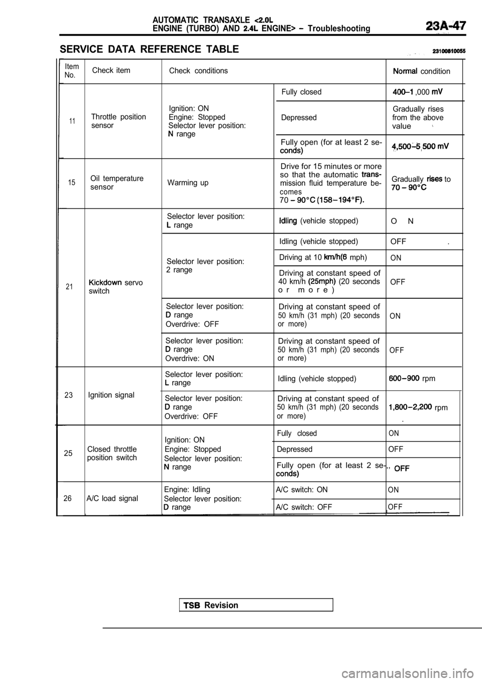
SERVICE DATA REFERENCE TABLE
Item
No.Check item Check conditions condition
Fully closed
,000
Ignition: ON Gradually rises
11Throttle positionEngine: Stopped Depressed from the above
sensor Selector lever position:
value range
Fully open (for at least 2 se-,
Drive for 15 minutes or more
so that the automatic
15Oil temperature Warming up mission fluid temperature be-Gradually to
sensor
comes
70
Selector lever position:
range (vehicle stopped)
Idling (vehicle stopped)O N
OFF .
21
23
25
servo
switch
Ignition signal
Closed throttle
position switch Selector lever position:
2 range
Selector lever position:
range
Overdrive: OFF
Selector lever position:
range
Overdrive: ON
Selector lever position:
range
Selector lever position:
range
Overdrive: OFF
Ignition: ON
Engine: Stopped
Selector lever position:
range Driving at 10
mph)ON
Driving at constant speed of
40 km/h (20 seconds
OFF
o r m o r e )
Driving at constant speed of
50 km/h (31 mph) (20 seconds ON
or more)
Driving at constant speed of
50 km/h (31 mph) (20 seconds OFF
or more)
Idling (vehicle stopped) rpm
Driving at constant speed of
50 km/h (31 mph) (20 seconds rpm
or more).
O NFully closed
Depressed OFF
Fully open (for at least 2 se-,,
26A/C load signal Engine: Idling
Selector lever position:
range A/C switch: ON
A/C switch: OFF
ON
OFF
Revision
Page 1059 of 2103
AUTOMATIC TRANSAXLE
ENGINE (TURBO) AND ENGINE> Troubleshooting
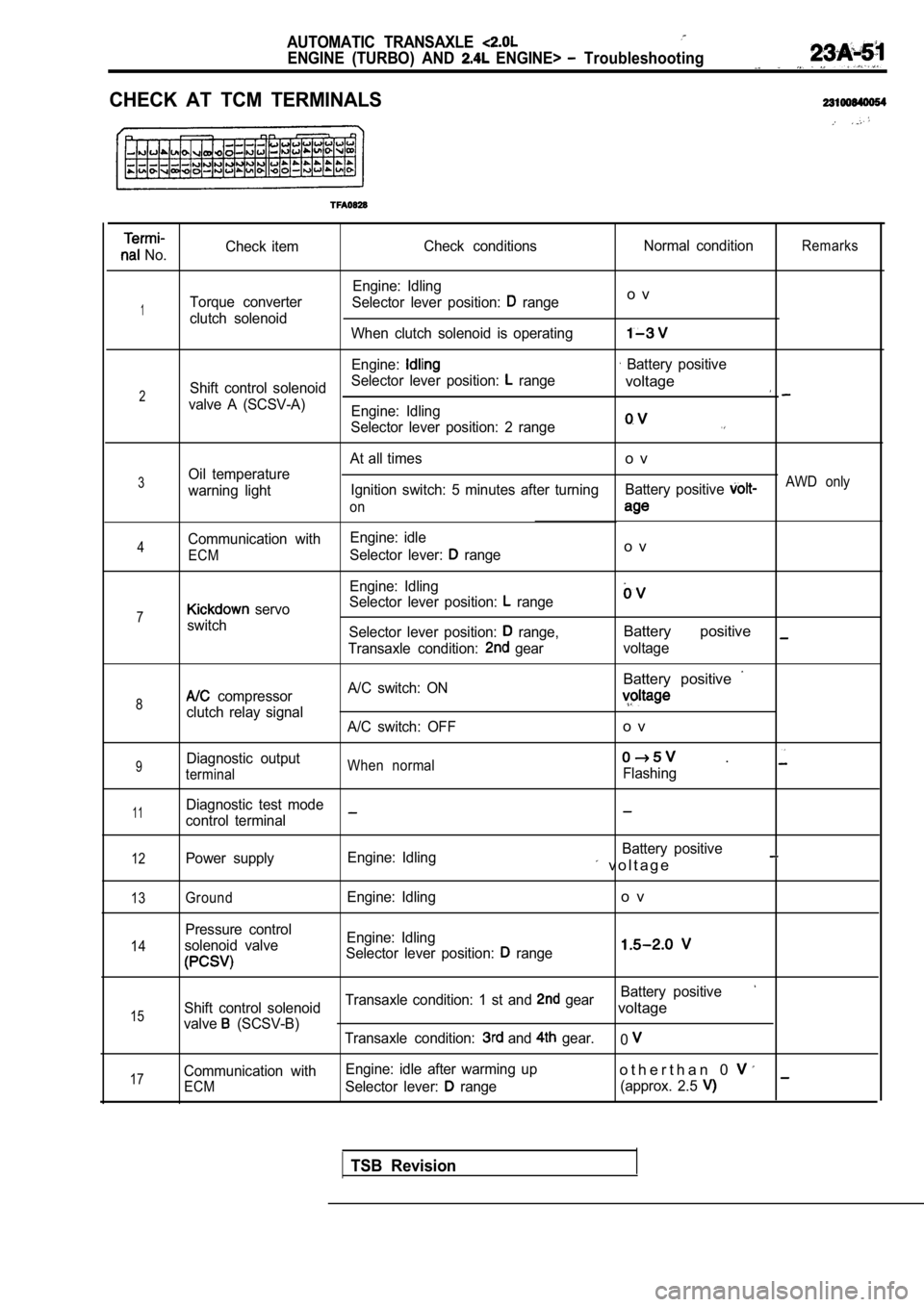
CHECK AT TCM TERMINALS
No.Check item
Check conditions Normal conditionRemarks
Engine: Idling
Torque converter Selector lever position:
rangeo v
1clutch solenoid
When clutch solenoid is operating
Engine: Battery positive
Shift control solenoid Selector lever position:
range
2voltage
valve A (SCSV-A)
Engine: Idling
Selector lever position: 2 range
At all timeso v
3Oil temperature
warning light Ignition switch: 5 minutes after turning
Battery positive AWD only
on
Communication with Engine: idle4Selector lever: rangeo vECM
Engine: Idling
Selector lever position:
range7 servo
switch Selector lever position:
range,Battery positive
Transaxle condition: gearvoltage
Battery positive
8 compressor A/C switch: ON
clutch relay signal
A/C switch: OFFo v
9Diagnostic outputWhen normal .
terminalFlashing
11Diagnostic test mode
control terminal
12Power supply Engine: Idling Battery positive v o l t a g e
13
14
15
17
GroundEngine: Idlingo v
Pressure control
solenoid valve Engine: Idling
Selector lever position:
range
Battery positive
Shift control solenoid Transaxle condition: 1 st and gearvoltage
valve (SCSV-B)
Transaxle condition: and gear.0
Communication with Engine: idle after warming upo t h e r t h a n 0
ECMSelector lever: range
(approx. 2.5
TSB Revision
Page 1060 of 2103
AUTOMATIC TRANSAXLE
ENGINE (TURBO) AND ENGINE> Troubleshooting
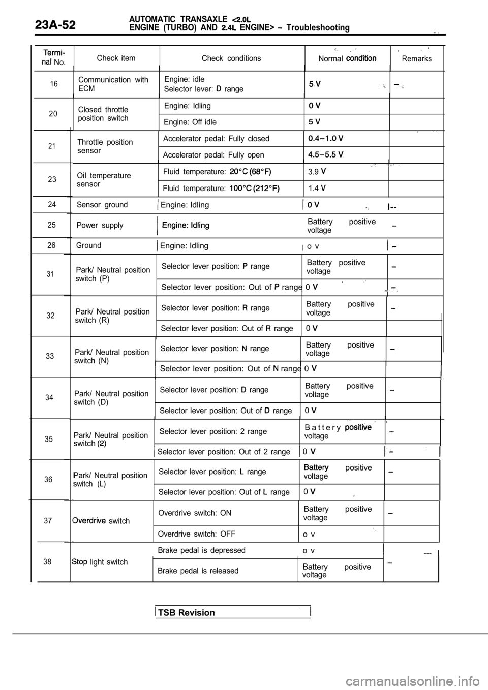
No.Check item
Check conditionsNormalRemarks
16Communication withEngine: idle
ECMSelector lever: range
20Closed throttle
position switch Engine: Idling
Engine: Off idle
21
23
24
25
26
31
32
33
34
35
36
37
38
Throttle position
sensor Accelerator pedal: Fully closed
Accelerator pedal: Fully open
Oil temperature
sensor Fluid temperature:
Fluid temperature:
3.9
1.4
Sensor ground Engine: IdlingI--
Power supplyBattery positive
voltage
Ground Engine: IdlingIo v
Park/ Neutral position
Selector lever position: rangeBattery positive
switch (P) voltage
Selector lever position: Out of range 0
Park/ Neutral position
Selector lever position: rangeBattery positive
switch (R) voltage
Selector lever position: Out of
range0
Park/ Neutral position Selector lever position: rangeBattery positive
switch (N) voltageSelector lever position: Out of range 0
Park/ Neutral position
Selector lever position: rangeBattery positive
switch (D) voltage
Selector lever position: Out of
range0
Park/ Neutral position Selector lever position: 2 rangeB a t t e r y
switchvoltage
Selector lever position: Out of 2 range 0
Park/ Neutral position
Selector lever position: range positive
switch (L)voltage
Selector lever position: Out of
range0
switch Overdrive switch: ON
Overdrive switch: OFF
Battery positive
voltage
o v
Brake pedal is depressedo v--- I
light switch Brake pedal is releasedBattery positive voltage
TSB Revision
Page 1063 of 2103

AUTOMATIC TRANSAXLE
ENGINE (TURBO) AND ENGINE> On-vehicle Service
ON-VEHICLE SERVICE
TRANSAXLE FLUID LEVEL CHECK
Refer to GROUP 00 Maintenance Service.
TRANSAXLE FLUID REPLACEMENT23100100176
Refer to GROUP 00 Maintenance Service.
TRANSFER OIL LEVEL CHECK23100110025
Refer to GROUP 00 Maintenance Service.
TRANSFER OIL REPLACEMENT23100120023
Refer to GROUP 00 Maintenance Service.
TSB Revision
Page 1070 of 2103
AUTOMATIC TRANSAXLE
ENGINE (TURBO) AND ENGINE> On-vehicle Service
Revision
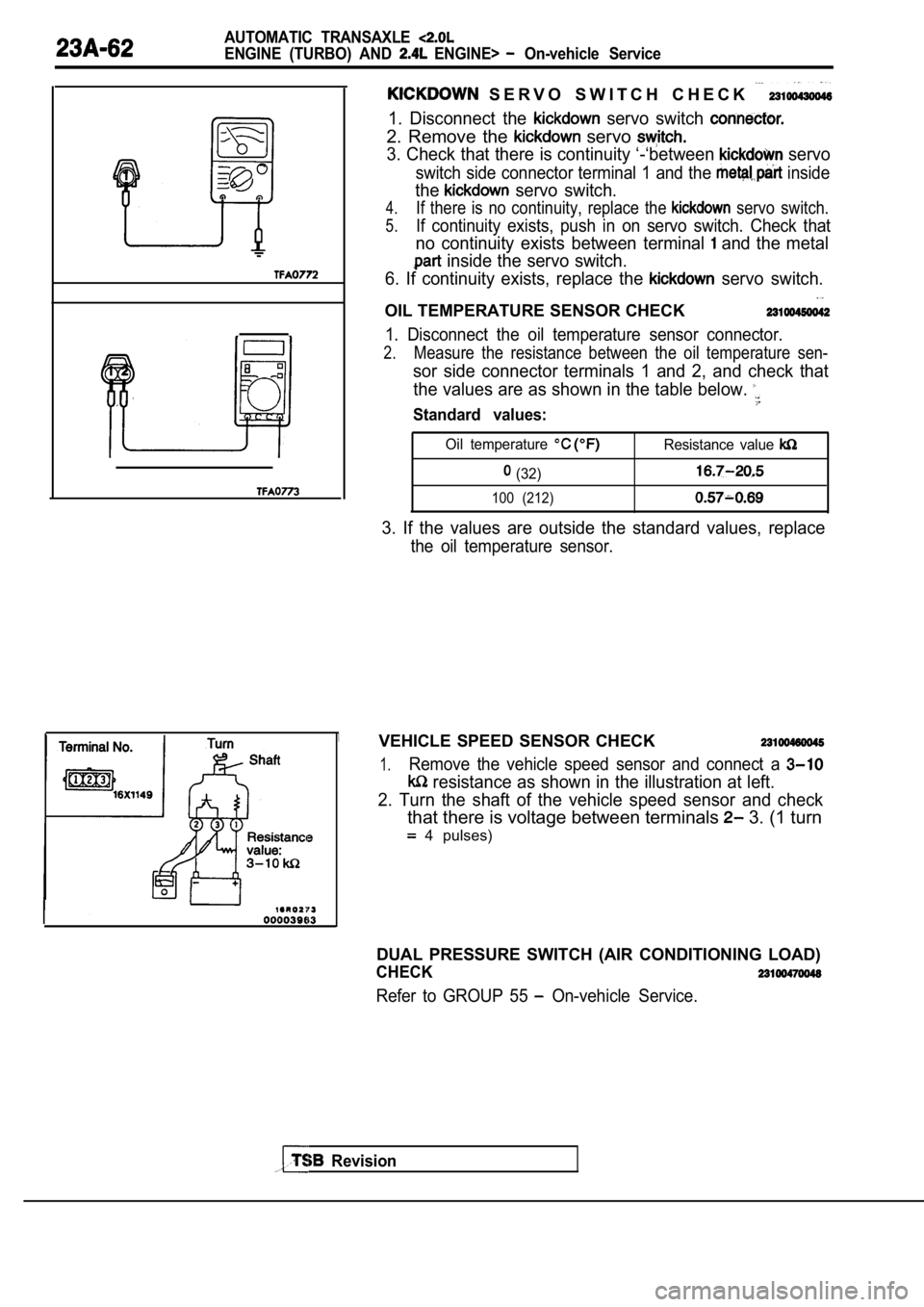
S E R V O S W I T C H C H E C K
1. Disconnect the servo switch
2. Remove the servo
3. Check that there is continuity ‘-‘between servo
switch side connector terminal 1 and the inside
the servo switch.
4.If there is no continuity, replace the servo switch.
5.If continuity exists, push in on servo switch. Check that
no continuity exists between terminal and the metal
inside the servo switch.
6. If continuity exists, replace the
servo switch.
OIL TEMPERATURE SENSOR CHECK
1. Disconnect the oil temperature sensor connector.
2.Measure the resistance between the oil temperature sen-
sor side connector terminals 1 and 2, and check that
the values are as shown in the table below.
Standard values:
Oil temperature Resistance value
(32)
100 (212)
3. If the values are outside the standard values, r eplace
the oil temperature sensor.
VEHICLE SPEED SENSOR CHECK
1.Remove the vehicle speed sensor and connect a
resistance as shown in the illustration at left.
2. Turn the shaft of the vehicle speed sensor and c heck
that there is voltage between terminals 3. (1 turn
4 pulses)
DUAL PRESSURE SWITCH (AIR CONDITIONING LOAD)
CHECK
Refer to GROUP 55 On-vehicle Service.