check oil MITSUBISHI SPYDER 1990 Service Repair Manual
[x] Cancel search | Manufacturer: MITSUBISHI, Model Year: 1990, Model line: SPYDER, Model: MITSUBISHI SPYDER 1990Pages: 2103, PDF Size: 68.98 MB
Page 631 of 2103
ENGINE (TURBO)
AND ENGINE>
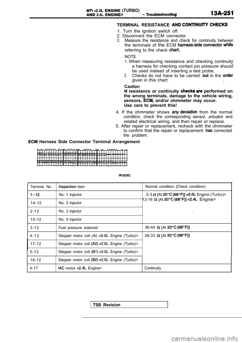
TERMINAL RESISTANCE
1. Turn the ignition switch off.
2. Disconnect the ECM connector.
3.Measure the resistance and check for continuity bet ween
the terminals of theECM
referring to the check
NOTE
1.When measuring resistance and checking continuity’
a harness for checking contact pin pressure should’
be used instead of inserting a test probe.
2.Checks do not have to be carried in the
given in this chart.,
Caution
If resistance or continuity performed on
the wrong terminals, damage to the vehicle wiring,
sensors,
and/or ohmmeter may occur.
Use care to prevent this!
4. If the ohmmeter shows
from the normal
condition, check the corresponding sensor, actuator and
related electrical wiring, and then repair or replace.
5. After repair or replacement, recheck with the oh mmeter
to confirm that the repair or replacement
corrected
the problem.
Harness Side Connector Terminal Arrangement
Terminal No. item Normal condition (Check condition)
No. 1 injector2-3 [At Engine (Turbo)>
No. 2 injector13-16 [At Engine>
14-12
2 - 1 2
No. 3 injector
15-12No. 4 injector
3 - 1 2Fuel pressure solenoid36-44 [At
4 - 1 2Stepper motor coil (Al) Engine (Turbo)>28-33 [At
17-12Stepper motor coil Engine (Turbo)>
5 - 1 2Stepper motor coil Engine (Turbo)>
18-12Stepper motor coil Engine (Turbo)>
4-17 motor Engine> Continuity
TSB Revision
Page 639 of 2103
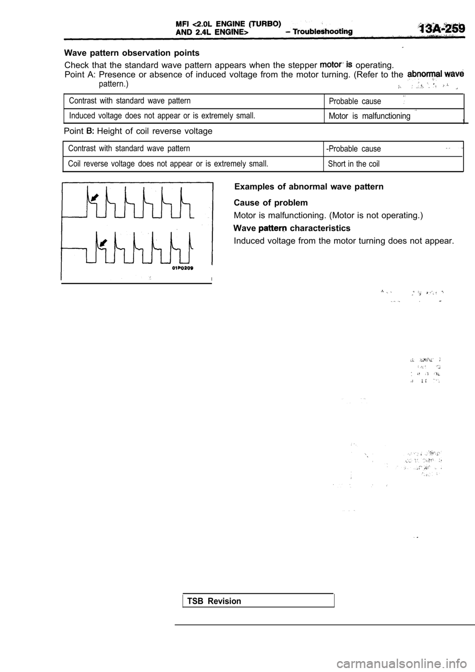
Wave pattern observation pointsCheck that the standard wave pattern appears when t he stepper
operating.
Point A: Presence or absence of induced voltage fro m the motor turning. (Refer to the
pattern.)
Contrast with standard wave pattern
Probable cause
Induced voltage does not appear or is extremely small.Motor is malfunctioning
Point Height of coil reverse voltage
Contrast with standard wave pattern
-Probable cause
Coil reverse voltage does not appear or is extremely small.
Short in the coil
Examples of abnormal wave pattern
Cause of problem
Motor is malfunctioning. (Motor is not operating.)
Wave
characteristics
Induced voltage from the motor turning does not app ear.
I
.
TSB Revision
Page 652 of 2103
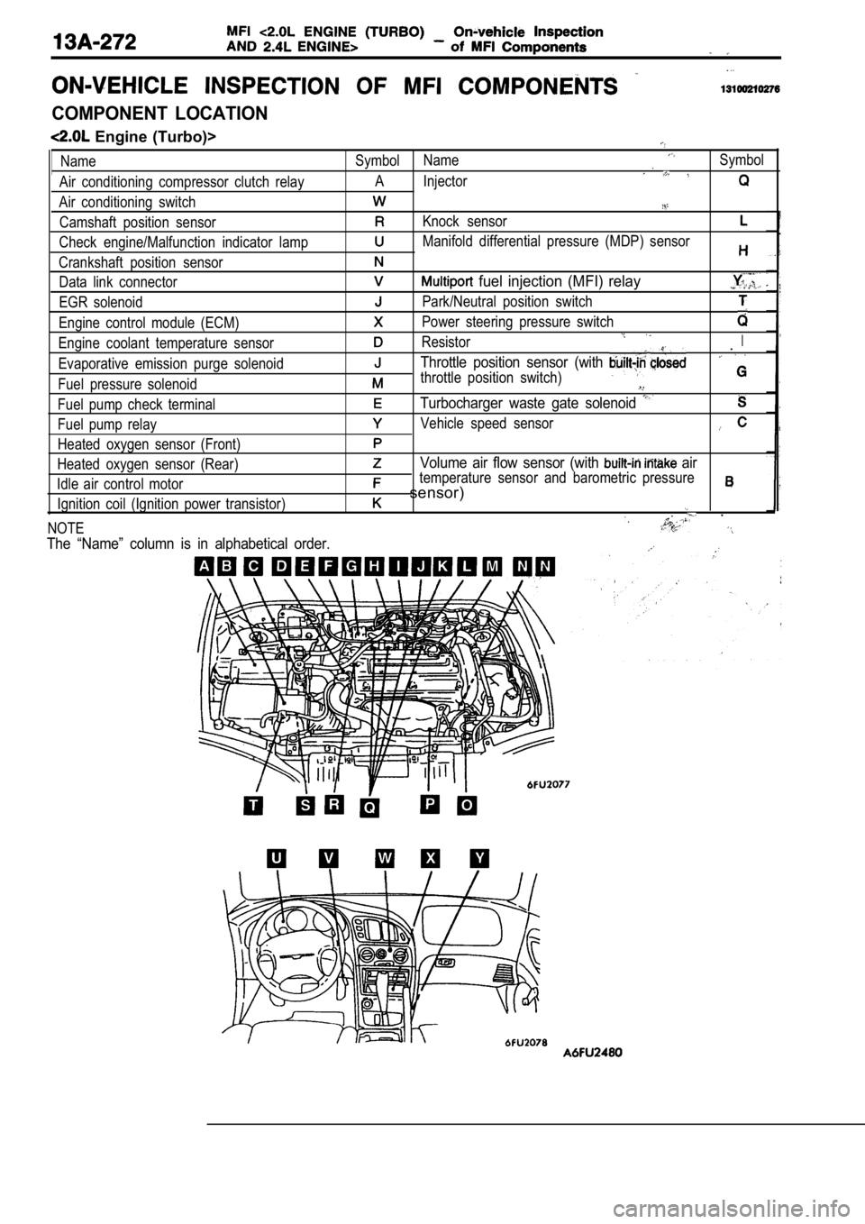
COMPONENT LOCATION
Engine (Turbo)>
Name
Air conditioning compressor clutch relay
Air conditioning switch Camshaft position sensor
Check engine/Malfunction indicator lamp
Crankshaft position sensor Data link connector
EGR solenoid
Engine control module (ECM)
Engine coolant temperature sensor
Evaporative emission purge solenoid
Fuel pressure solenoid
Fuel pump check terminal
Fuel pump relay
Heated oxygen sensor (Front)
Heated oxygen sensor (Rear)
Idle air control motor Ignition coil (Ignition power transistor)
NOTESymbol NameSymbol
A Injector
Knock sensor
Manifold differential pressure (MDP) sensor
fuel injection (MFI) relay
Park/Neutral position switch
Power steering pressure switch
ResistorI.
Throttle position sensor (with
throttle position switch)
Turbocharger waste gate solenoid
Vehicle speed sensor
Volume air flow sensor (with air
temperature sensor and barometric pressure
sensor)
.
The “Name” column is in alphabetical order.
Page 656 of 2103
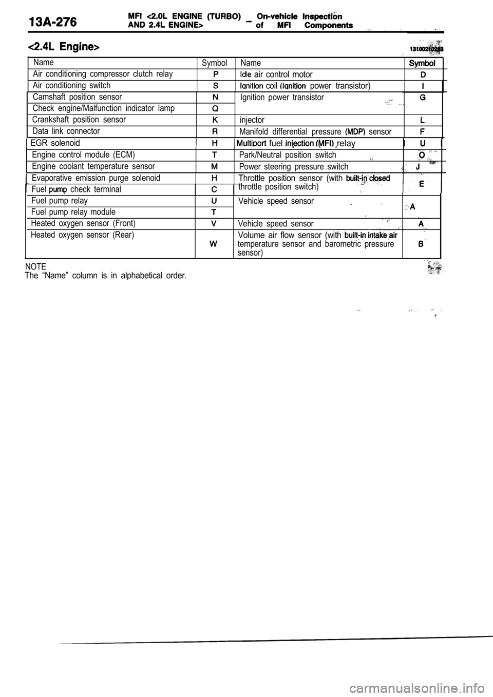
Name
Air conditioning compressor clutch relay
Air conditioning switchSymbol Name
air control motor
coil power transistor)
Camshaft position sensor
Check engine/Malfunction indicator lamp
Crankshaft position sensor
Data link connectorIgnition power transistor
injector
Manifold differential pressure sensor
EGR solenoid fuel relavI I
Engine control module (ECM)
Engine coolant temperature sensorPark/Neutral position switch
Power steering pressure switch
Evaporative emission purge solenoid
Fuel
check terminal
Throttle position sensor (with
throttle position switch)
Fuel pump relay
Fuel pump relay module
Heated oxygen sensor (Front)
Heated oxygen sensor (Rear)Vehicle speed sensor.
Vehicle speed sensor
Volume air flow sensor (with
temperature sensor and barometric pressure
sensor)
NOTE
The “Name” column is in alphabetical order.
Page 666 of 2103
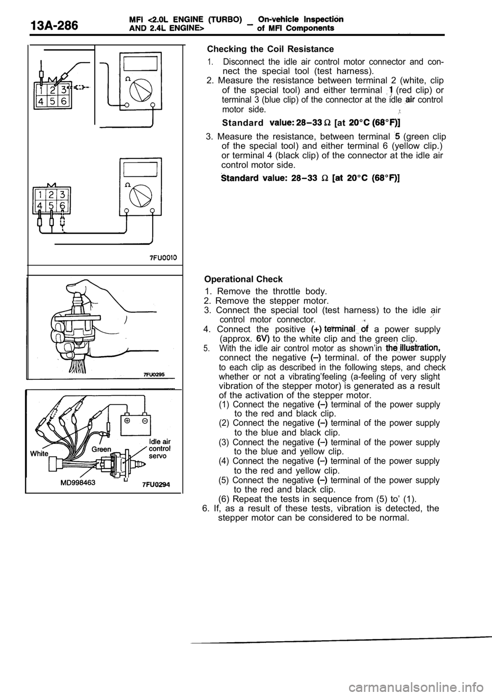
Checking the Coil Resistance
1.Disconnect the idle air control motor connector and con-
nect the special tool (test harness).
2. Measure the resistance between terminal 2 (white , clip
of the special tool) and either terminal
(red clip) or
terminal 3 (blue clip) of the connector at the idle control
motor side.
Standard [at
3. Measure the resistance, between terminal (green clip
of the special tool) and either terminal 6 (yellow clip.)
or terminal 4 (black clip) of the connector at the idle air
control motor side.
Operational Check
1. Remove the throttle body.
2. Remove the stepper motor. 3. Connect the special tool (test harness) to the i dle air
control motor connector.
4. Connect the positive a power supply
(approx.
to the white clip and the green clip.
5.With the idle air control motor as shown’in
connect the negative terminal. of the power supply
to each clip as described in the following steps, a nd check
whether or not a vibrating’feeling (a-feeling of ve ry slight
vibration of the stepper motor) is generated as a r esult
of the activation of the stepper motor.
(1) Connect the negative terminal of the power supply
to the red and black clip.
(2) Connect the negative terminal of the power supply
to the blue and black clip.
(3) Connect the negative terminal of the power supply
to the blue and yellow clip.
(4) Connect the negative terminal of the power supply
to the red and yellow clip.
(5) Connect the negative terminal of the power supply
to the red and black clip.
(6) Repeat the tests in sequence from (5) to’ (1).
6. If, as a result of these tests, vibration is det ected, the
stepper motor can be considered to be normal.
Page 670 of 2103
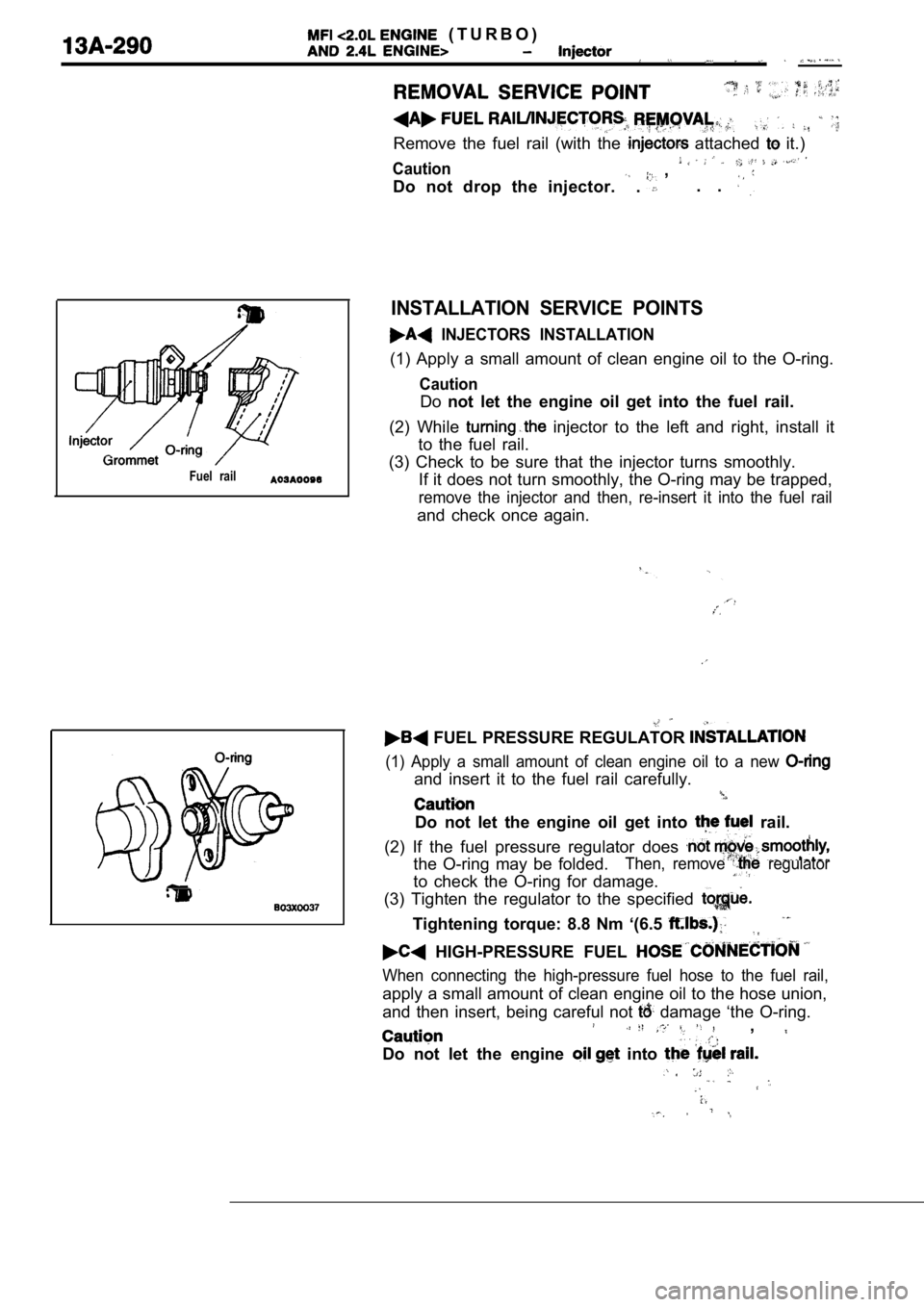
( T U R B O )
Remove the fuel rail (with the attached it.)
Caution ,
Do not drop the injector.
. . .
Fuel rail
INSTALLATION SERVICE POINTS
INJECTORS INSTALLATION
(1) Apply a small amount of clean engine oil to the O-ring.
Caution
Donot let the engine oil get into the fuel rail.
(2) While
injector to the left and right, install it
to the fuel rail.
(3) Check to be sure that the injector turns smooth ly.
If it does not turn smoothly, the O-ring may be tra pped,
remove the injector and then, re-insert it into the fuel rail
and check once again.
FUEL PRESSURE REGULATOR
(1) Apply a small amount of clean engine oil to a n ew
and insert it to the fuel rail carefully.
Do not let the engine oil get into rail.
(2) If the fuel pressure regulator does
the O-ring may be folded.Then, remove regulator
to check the O-ring for damage.
(3) Tighten the regulator to the specified
Tightening torque: 8.8 Nm ‘(6.5
HIGH-PRESSURE FUEL
When connecting the high-pressure fuel hose to the fuel rail,
apply a small amount of clean engine oil to the hose union,
and then insert, being careful not
damage ‘the O-ring.,
Do not let the engine into
,
Page 707 of 2103
E N G I N E C O O L I N G Water Pump Engine
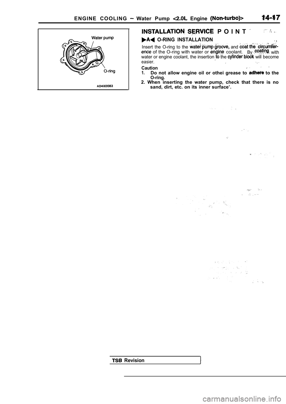
P O I N T
O-RING INSTALLATION ,
Insert the O-ring to the and
of the O-ring with water or coolant.By with
water or engine coolant, the insertion the will become
easier.
Caution1.Do not allow engine oil or othei grease to to theO-ring.2. When inserting the water pump, check that there is no
sand, dirt, etc. on its inner surface’.
Revision
Page 714 of 2103
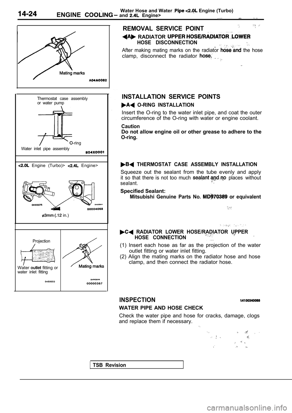
Water Hose and Water Engine (Turbo)
ENGINE and Engine>
Thermostat case assembly or water pump
O-ring
Water inlet pipe assembly
Engine (Turbo)> Engine>
in.)
Projection
Water fitting orwater inlet fitting
REMOVAL SERVICE POINT
RADIATOR
HOSE DISCONNECTION,After making mating marks on the radiator the hose
clamp, disconnect the radiator
INSTALLATION SERVICE POINTS
O-RING INSTALLATION
Insert the O-ring to the water inlet pipe, and coat the outer
circumference of the O-ring with water or engine co olant.
Caution
Do not allow engine oil or other grease to adhere t o the
O-ring.
THERMOSTAT CASE ASSEMBLY INSTALLATION
Squeeze out the sealant from the tube evenly and ap ply
it so that there is not too much places without
sealant.
Specified Sealant:
Mitsubishi Genuine Parts No. or equivalent
RADIATOR LOWER HOSE/RADIATOR UPPER
HOSE CONNECTION
(1) Insert each hose as far as the projection of th e water
outlet fitting or water inlet fitting.
(2) Align the mating marks on the radiator hose and hose
clamp, and then connect the radiator hose.
INSPECTION
WATER PIPE AND HOSE CHECK
Check the water pipe and hose for cracks, damage, c logs
and replace them if necessary.
TSB Revision
Page 718 of 2103
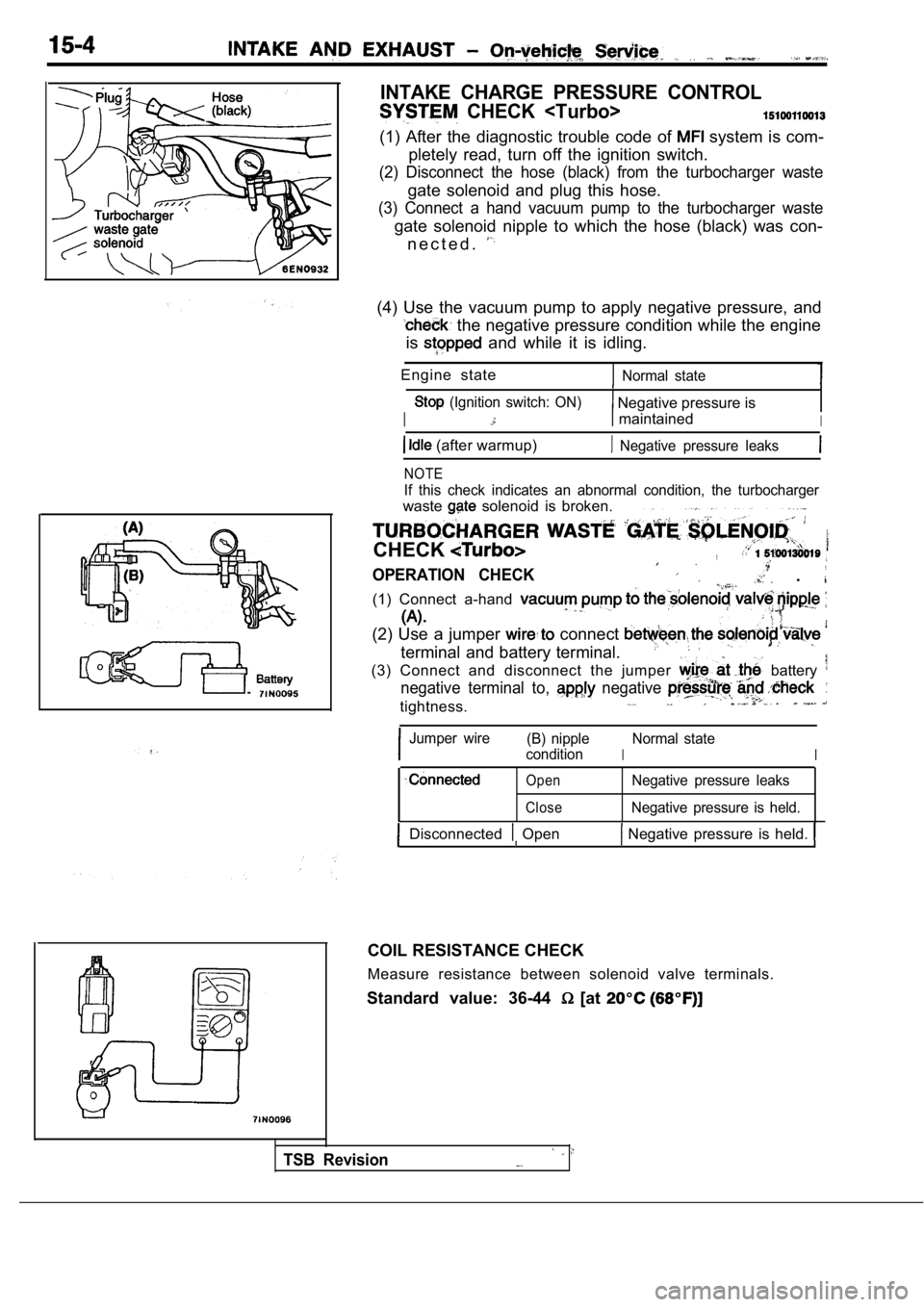
INTAKE CHARGE PRESSURE CONTROL
CHECK
(1) After the diagnostic trouble code of system is com-
pletely read, turn off the ignition switch.
(2) Disconnect the hose (black) from the turbocharg er waste
gate solenoid and plug this hose.
(3) Connect a hand vacuum pump to the turbocharger waste
gate solenoid nipple to which the hose (black) was con-
n e c t e d .
(4) Use the vacuum pump to apply negative pressure, and
the negative pressure condition while the engine
is
and while it is idling.
Engine state
Normal state
(Ignition switch: ON) Negative pressure is
I maintainedI
(after warmup) Negative pressure leaks
NOTE
If this check indicates an abnormal condition, the turbocharger
waste solenoid is broken.
CHECK,
OPERATION CHECK .
(1) Connect a-hand
(2) Use a jumper connect
terminal and battery terminal.
(3) Connect and disconnect the jumper
battery
negative terminal to, negative
tightness. .
Jumper wire (B) nipple
I
Normal state
condition
I
Open
CloseNegative pressure leaks
Negative pressure is held.
Disconnected Open Negative pressure is held.
COIL RESISTANCE CHECK
Measure resistance between solenoid valve terminals .
Standard value: 36-44
[at
TSB Revision
Page 727 of 2103
AND EXHAUST Intake Manifold
FUEL HOSE
Relieve pressure in line to prevent fuel outflow.
(Refer to GROUP
On-vehicle Service.)
Cautlon,
Cover fuel pipe line with shop after
sure as certain pressure may still
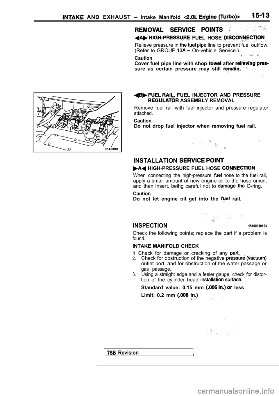
FUEL INJECTOR AND PRESSURE
ASSEMBLY REMOVAL
Remove fuel rail with fuel injector and pressure re gulator
attached.
Caution
Do not drop fuel injector when removing fuel rail.
INSTALLATION
HIGH-PRESSURE FUEL HOSE
When connecting the high-pressure hose to the fuel rail,
apply a small amount of new engine oil to the hose union,
and then insert, beihg careful not to
O-ring.
Caution
Do not let engine oil get into the rail.
INSPECTION15100310123
Check the following points; replace the part if a p roblem is
found.
INTAKE MANIFOLD CHECK
1. Check for damage or cracking of any
2.Check for obstruction of the negative
outlet port, and for obstruction of the water passa ge or
gas passage.
3.Using a straight edge and a feeler gauge, check for distor-
tion of the cylinder head
Standard value: 0.15 mm less
Limit: 0.2 mm
Revision