brakes MITSUBISHI SPYDER 1990 Service User Guide
[x] Cancel search | Manufacturer: MITSUBISHI, Model Year: 1990, Model line: SPYDER, Model: MITSUBISHI SPYDER 1990Pages: 2103, PDF Size: 68.98 MB
Page 1538 of 2103
REAR AXLE On-vehicle Service
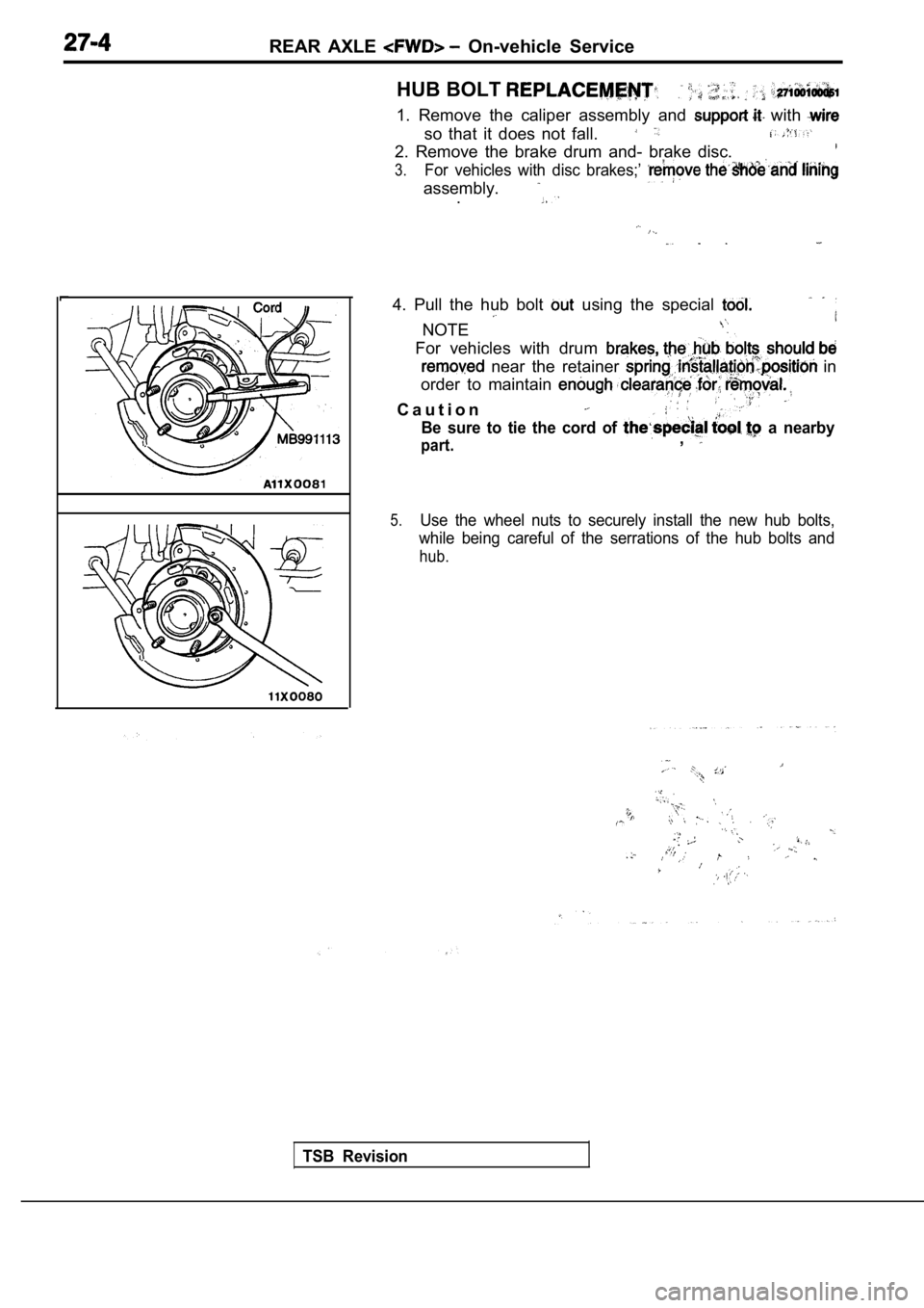
HUB BOLT
1. Remove the caliper assembly and with
so that it does not fall.
2. Remove the brake drum and- brake disc.
3.For vehicles with disc brakes;’
assembly..
4. Pull the hub bolt using the special
NOTE
For vehicles with drum
near the retainer in
order to maintain
C a u t i o n
Be sure to tie the cord of a nearby
part.,
5.Use the wheel nuts to securely install the new hub bolts,
while being careful of the serrations of the hub bo lts and
hub.
TSB Revision
.
,
,
,
Page 1539 of 2103
REAR AXLE Rear Hub Assembly
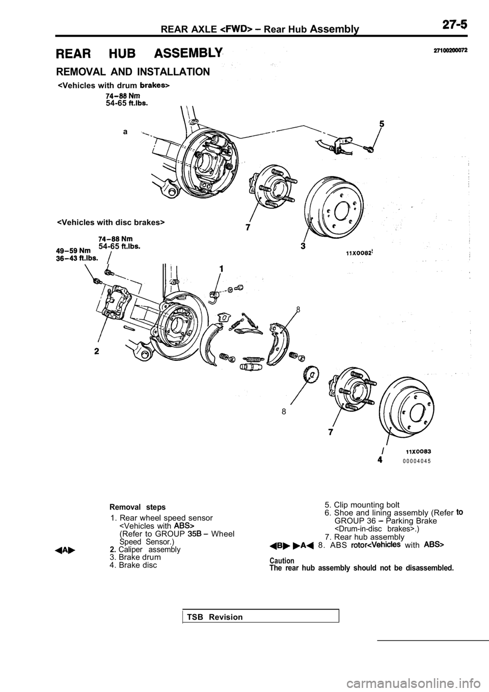
REMOVAL AND INSTALLATION
a
54-65
8
8
0 0 0 0 4 0 4 5
Removal steps
1. Rear wheel speed sensor
4. Brake disc 5. Clip mounting bolt
6. Shoe and lining assembly (Refer
GROUP 36 Parking Brake
7. Rear hub assembly 8. ABS with
CautionThe rear hub assembly should not be disassembled.
TSB Revision
Page 1552 of 2103
REAR AXLE Rear Hub Assembly
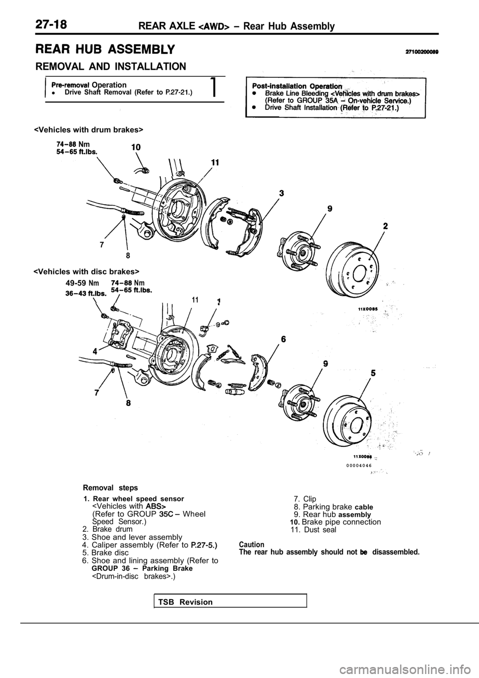
REMOVAL AND INSTALLATION
OperationlDrive Shaft Removal (Refer to 1
Nm
7
8
NmNm
11
Removal steps
1. Rear wheel speed sensor
2. Brake drum
3. Shoe and lever assembly
4. Caliper assembly (Refer to
5. Brake disc
6. Shoe and lining assembly (Refer to GROUP 36
Parking Brake
0 0 0 0 4 0 4 6
7. Clip8. Parking brake cable
9. Rear hub assembly
10. Brake pipe connection
11. Dust seal
CautionThe rear hub assembly should not disassembled.
TSB Revision
Page 1555 of 2103
REAR AXLE Drive
2 7 1 0 0 3 3 0 0 2 3
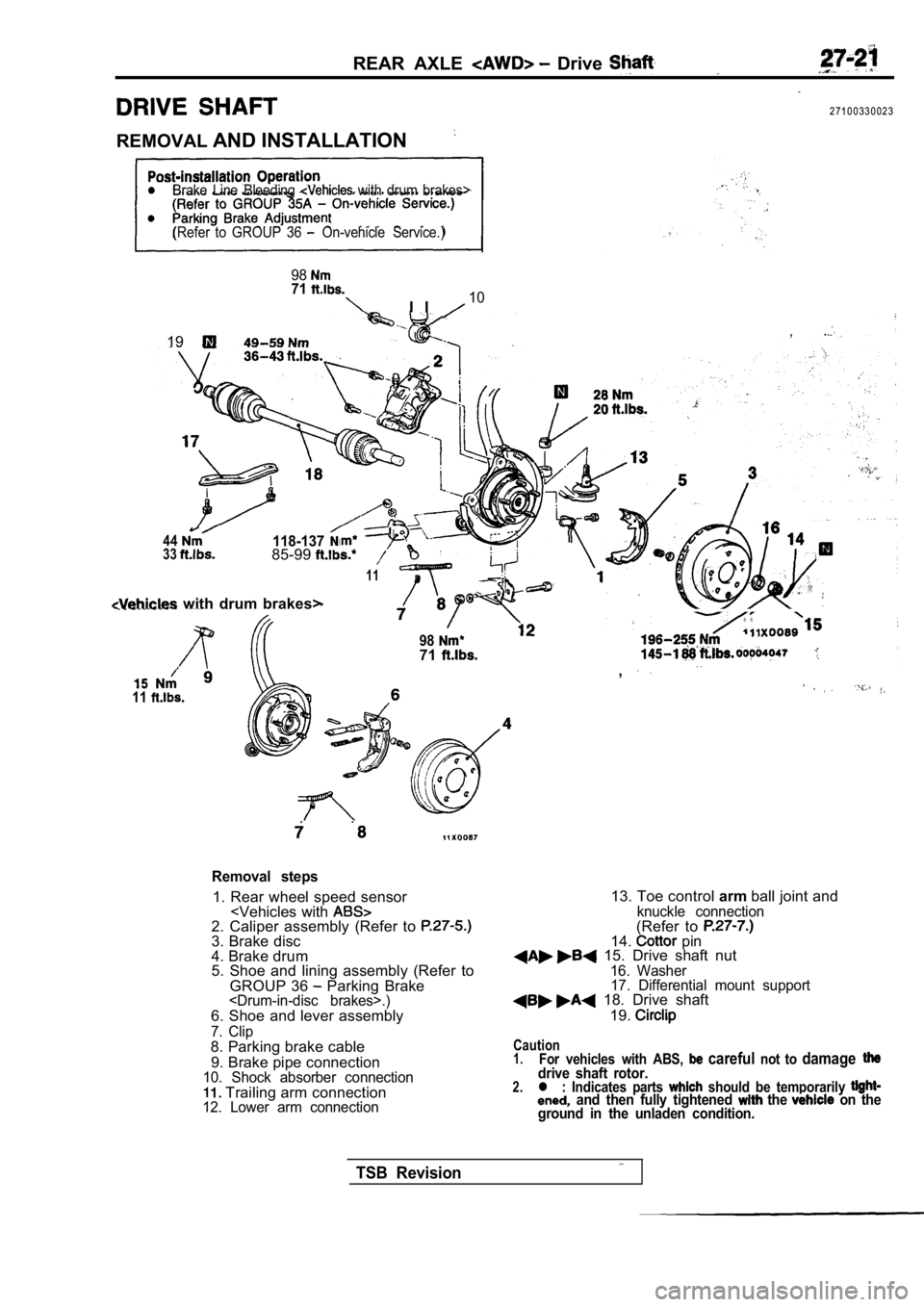
REMOVAL AND INSTALLATION
Brake Line Bleeding with drum brakes>
(Refer to GROUP 36
On-vehicle Service.)
9871
I I10
,19
44118-1373385-99
11
with drum brakes>
11
9871. .,
Removal steps
1. Rear wheel speed sensor
4. Brake drum
5. Shoe and lining assembly (Refer to
GROUP 36
Parking Brake
7. Clip8. Parking brake cable
9. Brake pipe connection
10. Shock absorber connection Trailing arm connection12. Lower arm connection
13. Toe control armball joint andknuckle connection(Refer to 14. pin 15. Drive shaft nut16. Washer
17. Differential mount support
18. Drive shaft
19.
Caution1.For vehicles with ABS, careful not to damagedrive shaft rotor.2.l : Indicates parts should be temporarily and then fully tightened the on the
ground in the unladen condition.
TSB Revision
Page 1563 of 2103
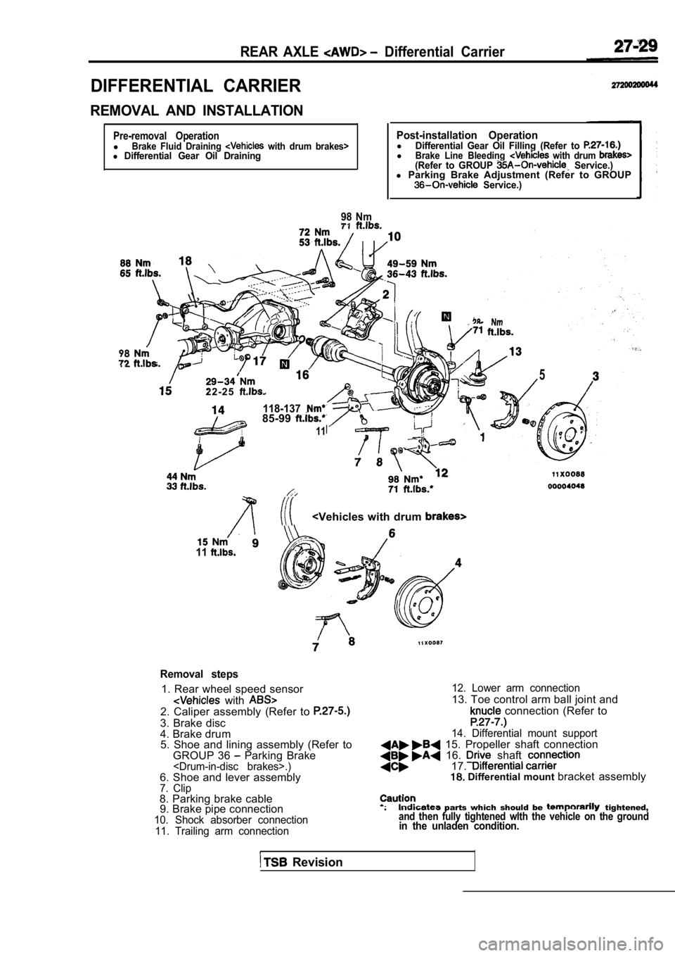
REAR AXLE Differential Carrier
DIFFERENTIAL CARRIER
REMOVAL AND INSTALLATION
Pre-removal OperationlBrake Fluid Draining with drum brakes>l Differential Gear Oil Draining
98 Nm
Post-installation OperationlDifferential Gear Oil Filling (Refer to lBrake Line Bleeding with drum (Refer to GROUP Service.)l Parking Brake Adjustment (Refer to GROUP Service.)
98
2 2 - 2 5
118-13785-99
11
5
11
Removal steps
1. Rear wheel speed sensor
with 2. Caliper assembly (Refer to
3. Brake disc
4. Brake drum
5. Shoe and lining assembly (Refer to
GROUP 36
Parking Brake
10. Shock absorber connection
11. Trailing arm connection 12. Lower arm connection
13. Toe control arm ball joint and
connection (Refer to
14. Differential mount support 15. Propeller shaft connection 16. shaft 17. Differential mount
bracket assembly
parts which should be tightened,and then fully tightened wlth the vehicle on the gr oundin the unladen condition.
Revision
Page 1623 of 2103
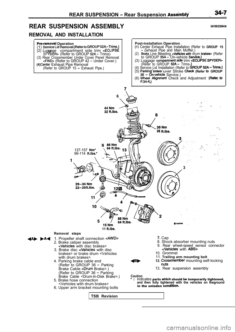
REAR SUSPENSION Rear Suspension
REAR SUSPENSION ASSEMBLY
REMOVAL AND INSTALLATION
Operation
(1)
(2) Lug agecompartment side trim SP (Refer to GROUP Trims)(3) Rear Crossmember Under Cover Panel Removal (Refer to GROUP 42 Under Cover.) Exhaust Pipe Removal(Refer to GROUP 15 Exhaust Pipe.)
3410033004
Post-installation Operation Center Exhaust Pipe Installation (Refer to GROUP 15Exhaust Pipe and Main Muffler,)(2) Line Bleeding drum (Referto GROUP On-vehicle (3) Luggage trim (Refer to GROUP Trims.
(4) Service Lid Installation (Refer to
(5) Brake Lever Stroke (Refer GROUP Service.)
(6) Check and Adjustment .
6
,
137-15799-114
.
l. .
3
Removal steps
11
1. Propeller shaft connection 2. Brake caliper assembly with disc brakes>
3. Brake disc with disc
brakes> or brake drum
4. Parking brake cable end
(Refer to GROUP 36
ParkingBrake Cable Brake>.)
(Refer to GROUP 36
ParkingBrake Cable
6. Upper arm bracket mounting bolts
Cap
8. Shock absorber mounting nuts
9. Rear wheel-speed sensor connector with 10. Grommet11. Trailing arm mounting bolt
12. mounting self-locking
13. Rear suspension assembly
Cautionindicatesparts should temporarily tightened,and then fully tightened with the vehicles on thegr oundin the unladen
TSB Revision
Page 1637 of 2103
SERVICE BRAKES
CONTENTS
BASIC BRAKE SYSTEM. . . . . . . . . . . . . . . . . . . . . . . . . . . . . . . . . . . . . . . . . . . . . . . .
ANTI-LOCK BRAKING SYSTEM (ABS) . . . . . . . . . . . . . . . . . . . . . . . . . . .358
ANTI-LOCK BRAKING SYSTEM (ABS) . . . . . . . . . . . . . . . . . . . . . . . . . . .
Page 1639 of 2103
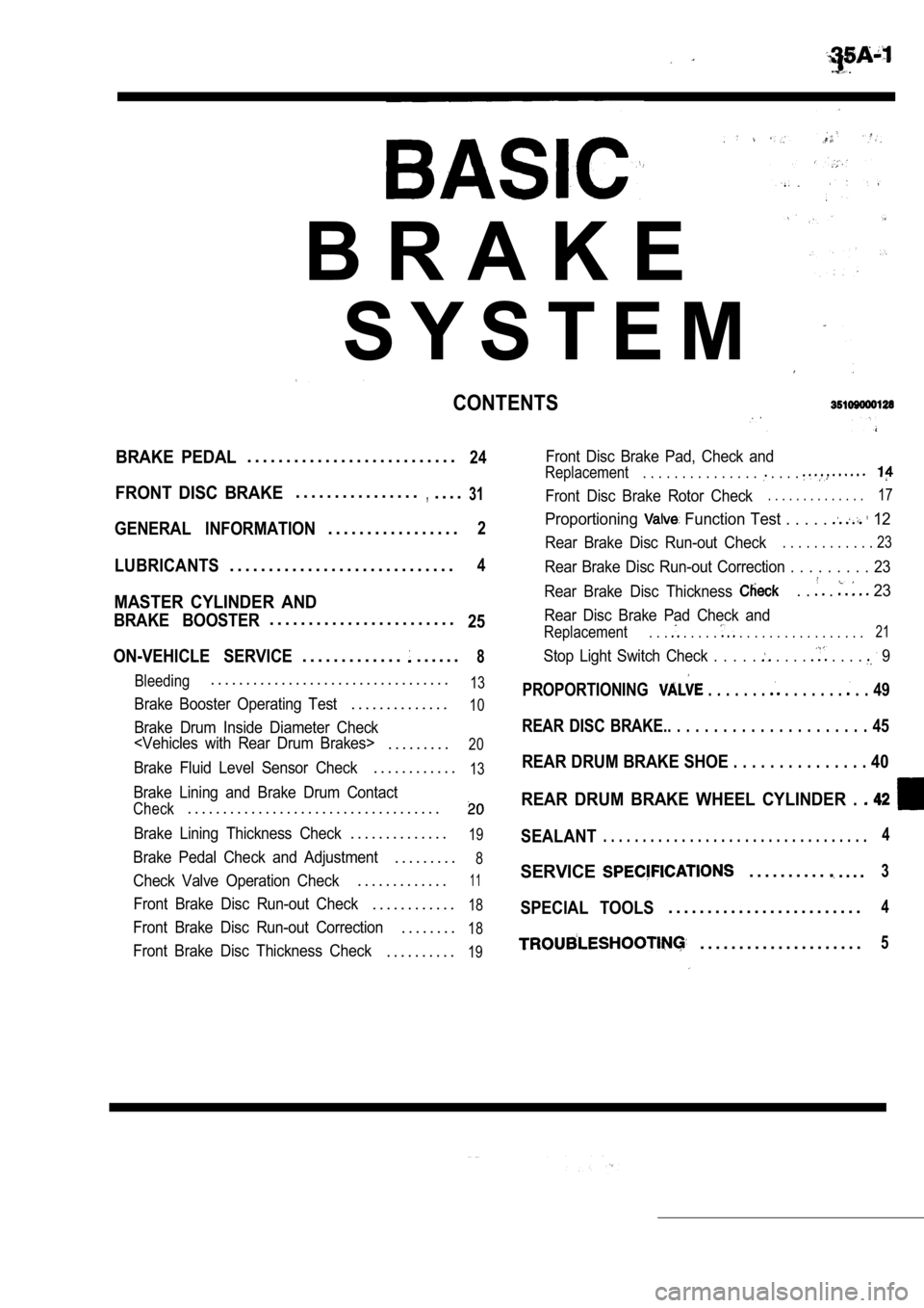
B R A K E
S Y S T E M
CONTENTS
BRAKE PEDAL. . . . . . . . . . . . . . . . . . . . . . . . . . .24
FRONT DISC BRAKE. . . . . . . . . . . . . . . .,. . . .31
GENERAL INFORMATION. . . . . . . . . . . . . . . . .2
LUBRICANTS. . . . . . . . . . . . . . . . . . . . . . . . . . . . .4
MASTER CYLINDER AND
BRAKE BOOSTER. . . . . . . . . . . . . . . . . . . . . . . .25
ON-VEHICLE SERVICE
. . . . . . . . . . . . .. . . . . .8
Bleeding. . . . . . . . . . . . . . . . . . . . . . . . . . . . . . . . . .13
Brake Booster Operating Test. . . . . . . . . . . . . .10
Brake Drum Inside Diameter Check
. . . . . . . . .20
Brake Fluid Level Sensor Check. . . . . . . . . . . .13
Brake Lining and Brake Drum Contact
Check. . . . . . . . . . . . . . . . . . . . . . . . . . . . . . . . . . . .
Brake Lining Thickness Check. . . . . . . . . . . . . .19
Brake Pedal Check and Adjustment. . . . . . . . .8
Check Valve Operation Check. . . . . . . . . . . . .11
Front Brake Disc Run-out Check. . . . . . . . . . . .18
Front Brake Disc Run-out Correction. . . . . . . .18
Front Brake Disc Thickness Check. . . . . . . . . .19
Front Disc Brake Pad, Check and
Replacement. . . . . . . . . . . . . . . . . . .
Front Disc Brake Rotor Check. . . . . . . . . . . . . .17
Proportioning Function Test . . . . . 12
Rear Brake Disc Run-out Check. . . . . . . . . . . . 23
Rear Brake Disc Run-out Correction . . . . . . . . . 23
Rear Brake Disc Thickness
. . . 23
Rear Disc Brake Pad Check and
Replacement. . . . . . . . . . . . . . . . . . . . . . . . . 21
Stop Light Switch Check . . . . . . . . . . . . . 9
PROPORTIONING . . . . . . . . . . . . . . . . 49
REAR DISC BRAKE.. . . . . . . . . . . . . . . . . . . . . . 45
REAR DRUM BRAKE SHOE . . . . . . . . . . . . . . . 40
REAR DRUM BRAKE WHEEL CYLINDER .
SEALANT. . . . . . . . . . . . . . . . . . . . . . . . . . . . . . . . . .4
SERVICE. . . . . . . . . .. . . .3
SPECIAL TOOLS. . . . . . . . . . . . . . . . . . . . . . . . .4
. . . . . . . . . . . . . . . . . . . . .5
Page 1640 of 2103
BRAKE SYSTEM General Information
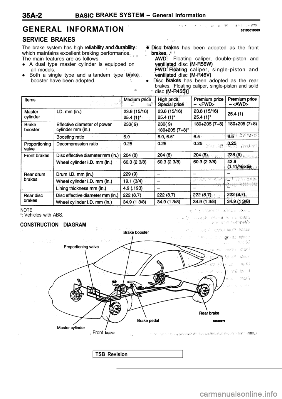
G E N E R A L I N F O R M A T I O N
. , . .
SERVICE BRAKES
The brake system has high
which maintains excellent braking performance.
has been adopted as the front
The main features are as follows. Floating caliper, double-piston and
l A dual type master cylinder is equipped on
disc
all models.
l Both a single type and a tandem type
c a l i p e r , s i n g l e - p i s t o n a n d
disc
booster have been adopted.l Disc has been adopted as the rear
brakes. [Floating caliper, single-piston and solid
disc
NOTE
Vehicles with ABS.
CONSTRUCTION DIAGRAM
, Front
TSB Revision
Page 1643 of 2103
BASIC BRAKE SYSTEM Troubleshooting
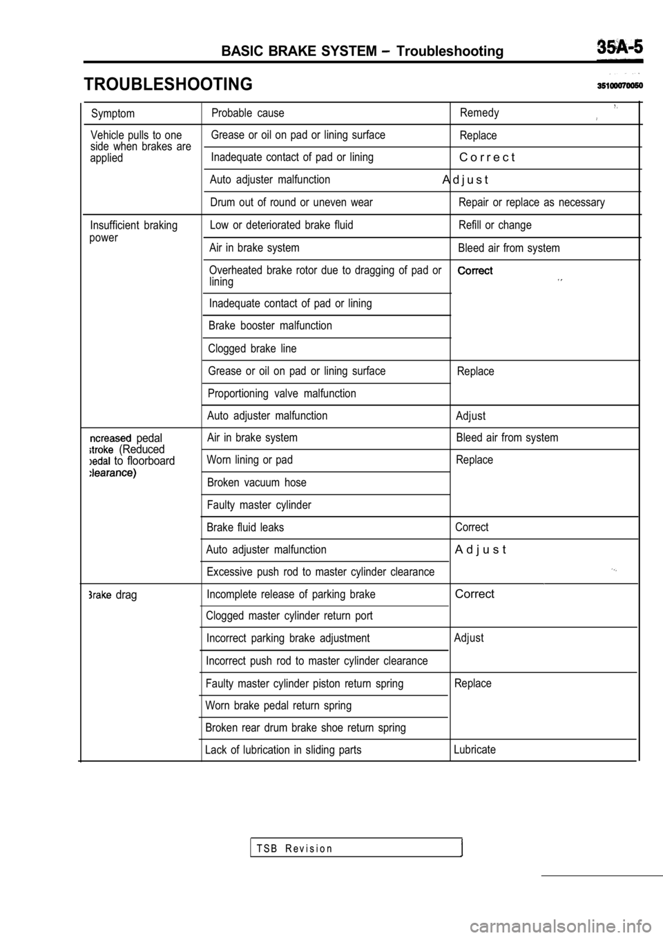
TROUBLESHOOTING
SymptomProbable cause
Remedy
Vehicle pulls to oneGrease or oil on pad or lining surface
Replace
side when brakes are
applied Inadequate contact of pad or lining
C o r r e c t
Auto adjuster malfunctionA d j u s t
Drum out of round or uneven wear Repair or replace a
s necessary
Insufficient braking Low or deteriorated brake fluid Refill or change
power Air in brake system Bleed air from system
Overheated brake rotor due to dragging of pad or
lining
Inadequate contact of pad or lining
Brake booster malfunction
Clogged brake line
pedal
(Reduced
to floorboard
drag
Grease or oil on pad or lining surface
Proportioning valve malfunction
Auto adjuster malfunction
Air in brake system
Worn lining or pad
Broken vacuum hose
Faulty master cylinder
Brake fluid leaks
Auto adjuster malfunction Excessive push rod to master cylinder clearance
Incomplete release of parking brake
Clogged master cylinder return port
Incorrect parking brake adjustment
Incorrect push rod to master cylinder clearance
Faulty master cylinder piston return spring
Worn brake pedal return spring
Broken rear drum brake shoe return spring Replace
Adjust Bleed air from system
Replace
Correct
A d j u s t
Correct
Adjust Replace
Lack of lubrication in sliding parts Lubricate
T S B R e v i s i o n