drain bolt MITSUBISHI SPYDER 1990 Service User Guide
[x] Cancel search | Manufacturer: MITSUBISHI, Model Year: 1990, Model line: SPYDER, Model: MITSUBISHI SPYDER 1990Pages: 2103, PDF Size: 68.98 MB
Page 1110 of 2103
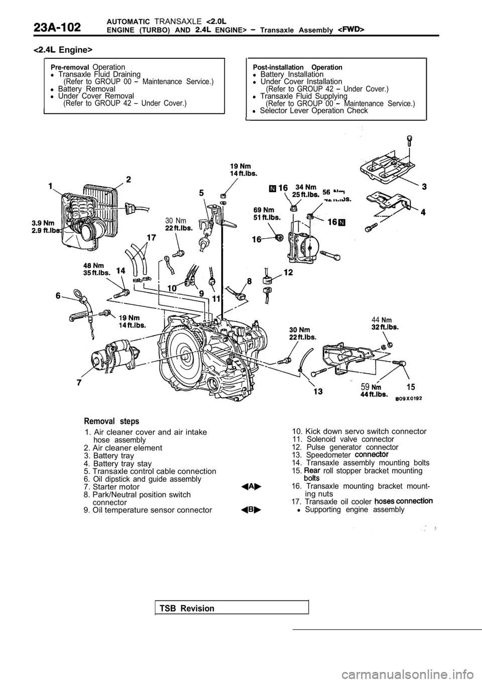
AUTOMATICTRANSAXLE
ENGINE (TURBO) AND ENGINE> Transaxle Assembly
Engine>
Pre-removalOperationl Transaxle Fluid Draining(Refer to GROUP 00 Maintenance Service.)l Battery Removall Under Cover Removal(Refer to GROUP 42 Under Cover.)I
I
I
Post-installation Operationl Battery Installationl Under Cover Installation(Refer to GROUP 42 Under Cover.)l Transaxle Fluid Supplying(Refer to GROUP 00 Maintenance Service.)l Selector Lever Operation Check
30 Nm
5915
44Nm
TSB Revision
Removal steps
1. Air cleaner cover and air intakehose assembly2. Air cleaner element
3. Battery tray
4. Battery tray stay
5. Transaxle control cable connection
6. Oil dipstick and guide assembly7. Starter motor
8. Park/Neutral position switch
connector9. Oil temperature sensor connector
10. Kick down servo switch connector11. Solenoid valve connector
12. Pulse generator connector
13. Speedometer
14. Transaxle assembly mounting bolts
15. roll stopper bracket mounting
16. Transaxle mounting bracket mount-
ing nuts17. Transaxle oil cooler l Supporting engine assembly
Page 1114 of 2103
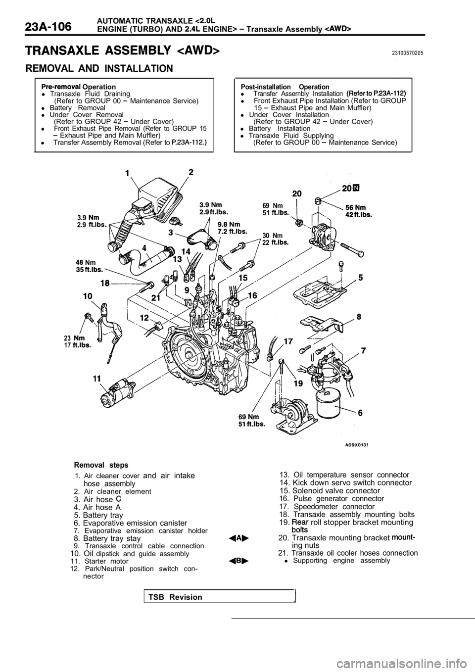
AUTOMATIC TRANSAXLE
ENGINE (TURBO) AND ENGINE> Transaxle Assembly
REMOVAL ANDINSTALLATION
23100570205
Operation
l Transaxle Fluid Draining
(Refer to GROUP 00
Maintenance Service)
l Battery Removal
l Under Cover Removal
(Refer to GROUP 42
Under Cover)
lFront Exhaust Pipe Removal (Refer to GROUP 15 Exhaust Pipe and Main Muffler)
l Transfer Assembly Removal (Refer to
3.92.9
Nm
Post-installation OperationlTransfer Assembly Installation l Front Exhaust Pipe Installation (Refer to GROUP
15 Exhaust Pipe and Main Muffler)
l Under Cover Installation
(Refer to GROUP 42
Under Cover)
l Battery Installation
l Transaxle Fluid Supplying
(Refer to GROUP 00
Maintenance Service)
30 Nm
22
23 17
69 Nm51
Removal steps
1. Air cleaner cover and air intake
hose assembly2. Air cleaner element
3. Air hose
4. Air hose A
5. Battery tray
6. Evaporative emission canister
7. Evaporative emission canister holder
8. Battery tray stay
9. Transaxle control cable connection
10. Oil dipstick and guide assembly
11. Starter motor
12. Park/Neutral position switch con- nector
13. Oil temperature sensor connector14. Kick down servo switch connector
15. Solenoid valve connector
16. Pulse generator connector
17. Speedometer connector
18. Transaxle assembly mounting bolts
19. roll stopper bracket mounting
20. Transaxle mounting bracket
ing nuts21. Transaxle oil cooler hoses connectionl Supporting engine assembly
TSB Revision
Page 1200 of 2103
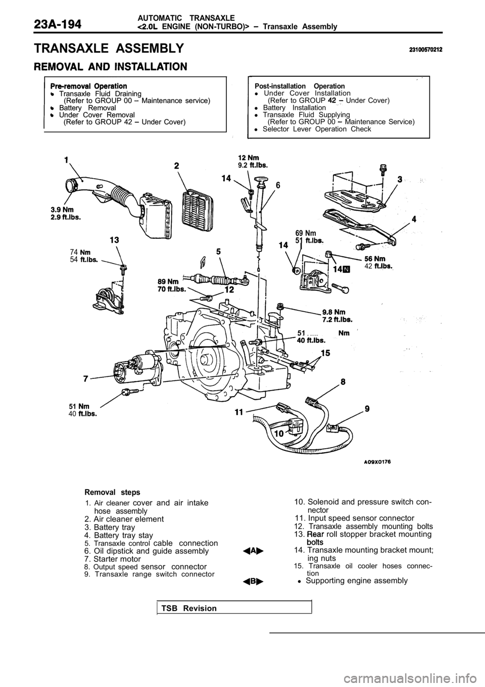
AUTOMATIC TRANSAXLE
ENGINE (NON-TURBO)> Transaxle Assembly
TRANSAXLE ASSEMBLY
l Transaxle Fluid Draining
l Transaxle Fluid Draining
(Refer to GROUP 00 Maintenance service)
(Refer to GROUP 00 Maintenance service)
l Battery Removal
l Battery Removal
l Under Cover Removal
l Under Cover Removal
(Refer to GROUP 42
Under Cover)
(Refer to GROUP 42 Under Cover)
7454
Post-installation Operationl Under Cover Installation
(Refer to GROUP Under Cover)
l Battery Installation
l Transaxle Fluid Supplying
(Refer to GROUP 00
Maintenance Service)
l Selector Lever Operation Check
9.2
6
5140
69 Nm51 I
42
51
Removal steps
1. Air cleaner cover and air intake
hose assembly2. Air cleaner element
3. Battery tray
4. Battery tray stay 5. Transaxle control cable connection
6. Oil dipstick and guide assembly
7. Starter motor
8. Output speed sensor connector
9. Transaxle range switch connector
10. Solenoid and pressure switch con-
nector11. Input speed sensor connector
12. Transaxle assembly mounting bolts13. roll stopper bracket mounting
14. Transaxle mounting bracket mount; ing nuts
15. Transaxle oil cooler hoses connec- tion
l Supporting engine assembly
TSB Revision
Page 1215 of 2103
AUTOMATIC
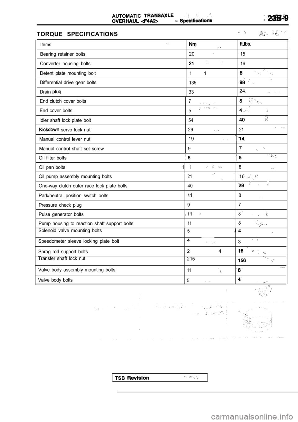
TORQUE SPECIFICATIONS
Items
Bearing retainer bolts2015
Converter housing bolts16
Detent plate mounting bolt1 1
Differential drive gear bolts135
Drain3324.
End clutch cover bolts
End cover bolts
Idler shaft lock plate bolt
servo lock nut
7
5
54
2921
Manual control lever nut19
Manual control shaft set screw97
Oil filter bolts
Oil pan bolts
Oil pump assembly mounting bolts
One-way clutch outer race lock plate bolts
Park/neutral position switch bolts
Pressure check plug
Pulse generator bolts
Pump housing to reaction shaft support bolts1 18--
21
16
40 ,
8
9 7
8 ,
118 .
Solenoid valve mounting bolts5
Speedometer sleeve locking plate bolt3
Sprag rod support bolts
Transfer shaft lock nut2 4
215
Valve body assembly mounting bolts
Valve body bolts11
.5
TSB
Page 1295 of 2103
A U T O M A T I C T R A N S A X L E
OVERHAUL
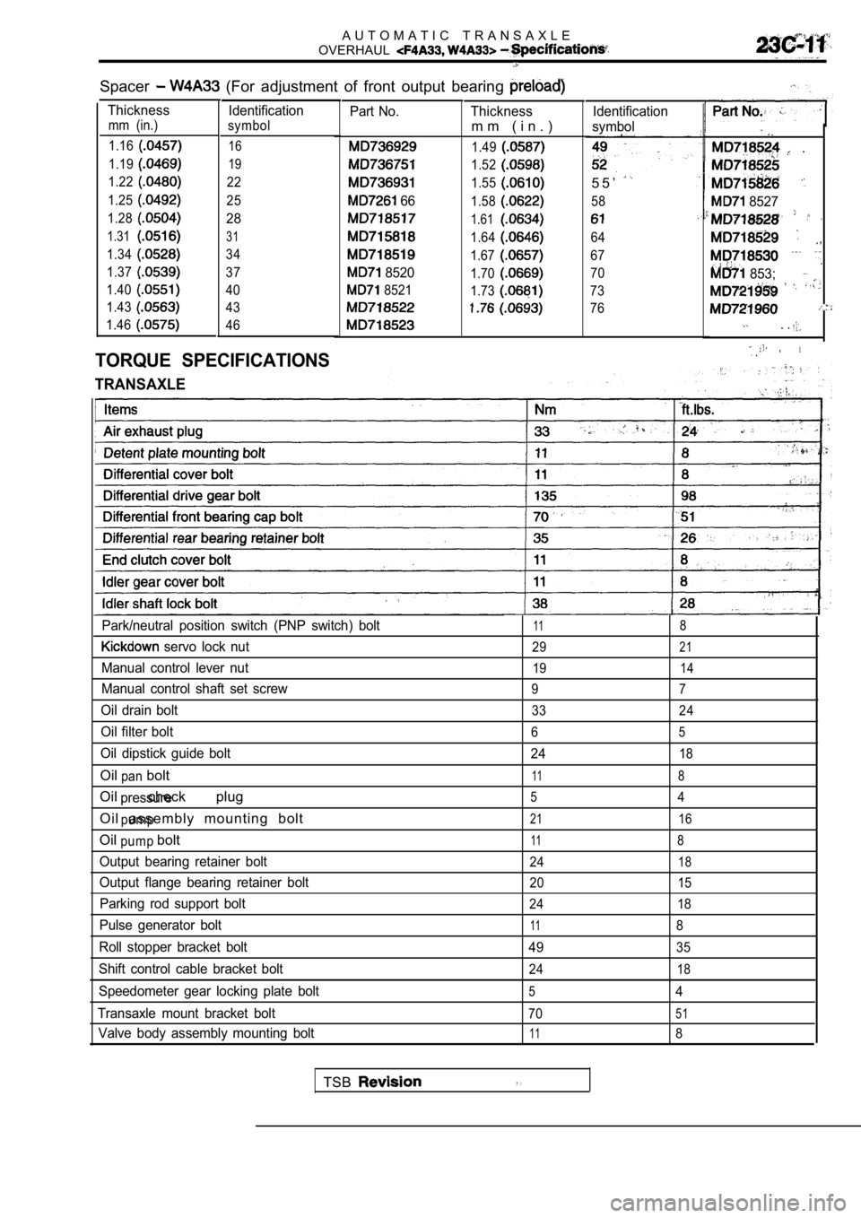
Spacer (For adjustment of front output bearing
Thickness Identification
mm (in.) symbol
1.16
16
1.1919
1.2222
1.25
25
1.28
28
1.3131
1.3434
1.37
37
1.40
40
1.43
43
1.46
46
TORQUE SPECIFICATIONS
TRANSAXLE
Part No.
66
8520
8521
Thickness
m m ( i n . )
1.49
1.52
1.55
1.58
1.61
1.64
1.67
1.70
1.73
Identification
symbol
5 5 ’
58
64
67
70
73
76
.
8527
853;
. .
.
Park/neutral position switch (PNP switch) bolt118
servo lock nut2921
Manual control lever nut1914
Manual control shaft set screw9 7
Oil drain bolt33 24
Oil filter bolt65
Oil dipstick guide bolt 2418
Oil boltpan118
Oil check plugpressure54
Oil assembly mounting boltpump2116
Oil boltpump118
Output bearing retainer bolt2418
Output flange bearing retainer bolt20 15
Parking rod support bolt24 18
Pulse generator bolt118
Roll stopper bracket bolt4935
Shift control cable bracket bolt2418
Speedometer gear locking plate bolt54
Transaxle mount bracket bolt
7051
Valve body assembly mounting bolt118
TSB
Page 1296 of 2103
AUTOMATIC TRANSAXLE
OVERHAUL
Specifications
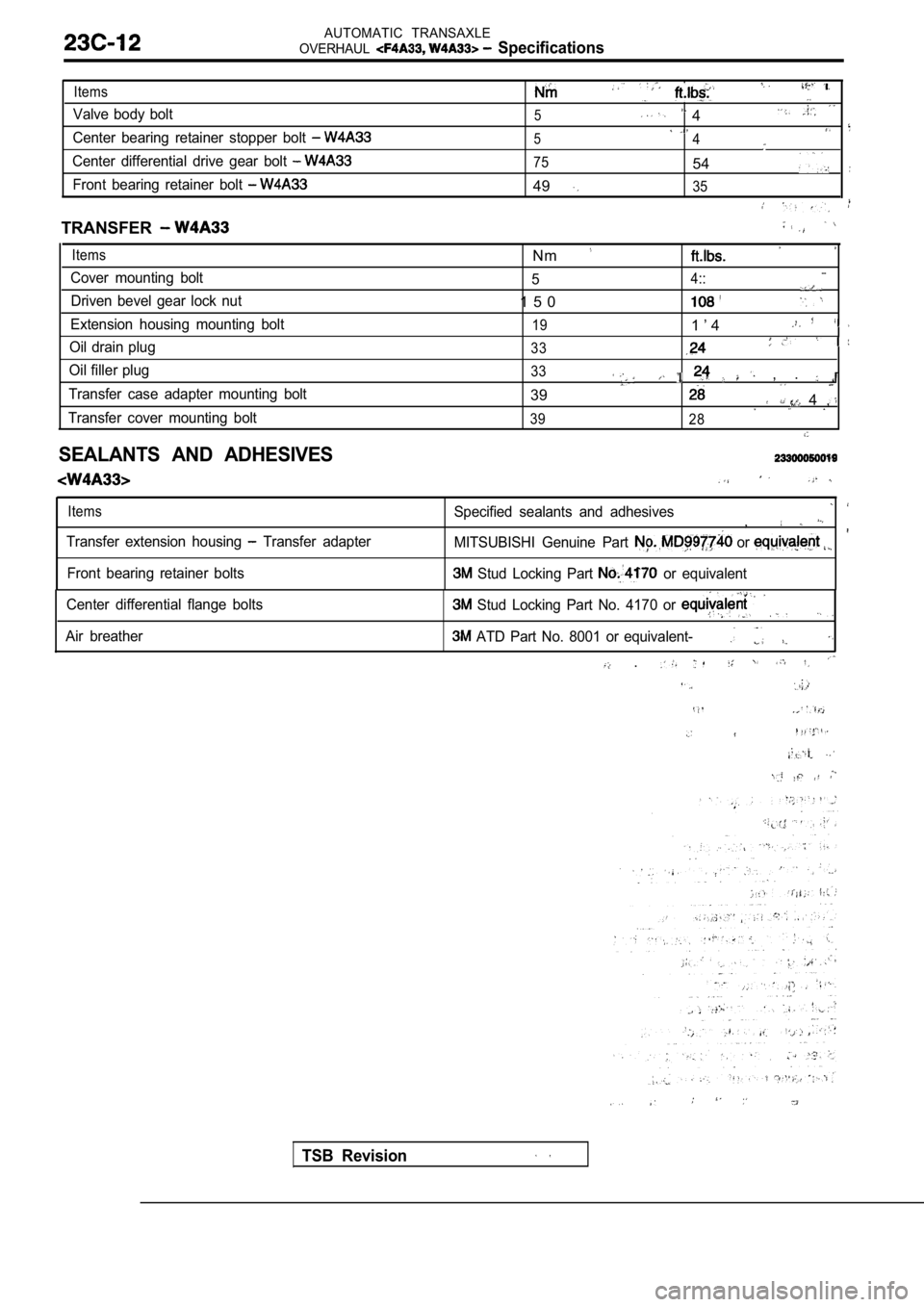
Items
Valve body bolt
Center bearing retainer stopper bolt
Center differential drive gear bolt
Front bearing retainer bolt
5 4
54
7554
4935
TRANSFER
Items
Cover mounting bolt Driven bevel gear lock nut
Extension housing mounting bolt
Oil drain plug
Oil filler plug
Transfer case adapter mounting bolt
Transfer cover mounting bolt
Nm_ _54::
1 5 0
191 ’ 4
33
33 , .
39 4 ,
39 28
SEALANTS AND ADHESIVES
Items
Transfer extension housing Transfer adapter Specified sealants and adhesives
,
MITSUBISHI Genuine Part or
Front bearing retainer bolts Stud Locking Part or equivalent
Center differential flange bolts
Air breather
Stud Locking Part No. 4170 or
ATD Part No. 8001 or equivalent-
.
TSB Revision
Page 1549 of 2103
R E A R
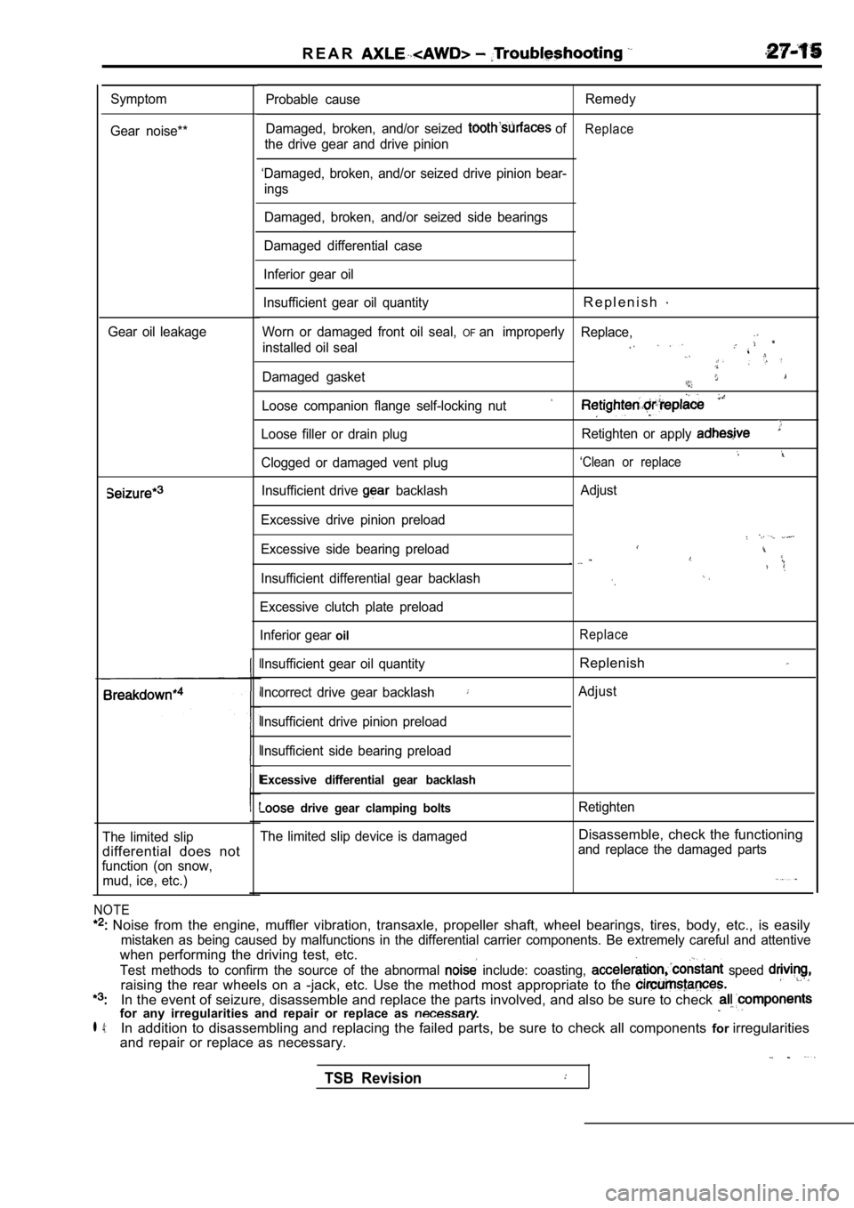
Symptom
Gear noise**
Gear oil leakage
The limited slip
differential does not
function (on snow, mud, ice, etc.)
NOTE
Noise from the engine, muffler vibration, transaxl e, propeller shaft, wheel bearings, tires, body, etc., is easily
mistaken as being caused by malfunctions in the dif ferential carrier components. Be extremely careful and attentive
when performing the driving test, etc.
Test methods to confirm the source of the abnormal include: coasting, speed
raising the rear wheels on a -jack, etc. Use the me thod most appropriate to the
In the event of seizure, disassemble and replace the parts involved, and also be sure to check for any irregularities and repair or replace as
l 4:In addition to disassembling and replacing the failed parts, be sure to check all components forirregularities
and repair or replace as necessary.
Probable cause Remedy
Damaged, broken, and/or seized
ofReplace
the drive gear and drive pinion
‘Damaged, broken, and/or seized drive pinion bear- ings
Damaged, broken, and/or seized side bearings
Damaged differential case
Inferior gear oil
Insufficient gear oil quantity
R e p l e n i s h
Worn or damaged front oil seal, OFan improperly Replace,
installed oil seal
Damaged gasket
Loose companion flange self-locking nut
Loose filler or drain plug Retighten or apply
‘Clean or replaceClogged or damaged vent plug
Insufficient drive
backlash
Excessive drive pinion preload
Excessive side bearing preload
Insufficient differential gear backlash
Excessive clutch plate preload
Inferior gear
oil
Insufficient gear oil quantity
Incorrect drive gear backlash
Insufficient drive pinion preload
Insufficient side bearing preload
Excessive differential gear backlash
drive gear clamping bolts
The limited slip device is damaged Adjust
Replace
Replenish
Adjust
Retighten
Disassemble, check the functioning
and replace the damaged parts
TSB Revision
Page 1599 of 2103
POWER PLANT MOUNT Crossmember
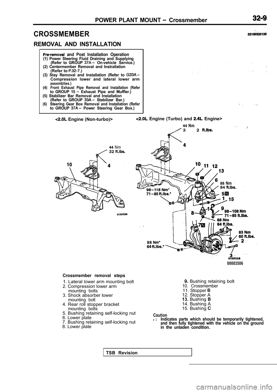
CROSSMEMBER
REMOVAL AND INSTALLATION
and Post Installation Operation(1) Power Steering Fluid Draining and Supplying(Refer to GROUP On-vehicle Service.)
(2) Centermember Removal and Instrallation
(Refer to (3) Stay Removal and Installation (Refer to Compression lower and lateral lower armassemblies.)(4)Front Exhaust Pipe Removal and Installation (Referto GROUP 15 Exhaust Pipe and Muffler.)
(5) Stabilizer Bar Removal and Installation (Refer to GROUP
Stabilizer Bar.)(6)Steering Gear Box Removal and Installation (Referto GROUP Power Steering Gear Box.)
Engine (Non-turbo)>
44Nm32
Engine (Turbo) and Engine>
44Nm3 2
88Nm84
88
00003506
Crossmember removal steps
1. Lateral lower arm mounting bolt
2. Compression lower arm
mounting bolts3. Shock absorber lowermounting bolt4. Rear roll stopper bracketmounting bolts5. Bushing retaining self-locking nut
6. Lower plate
7. Bushing retaining self-locking nut
8. Lower plate
Bushing retaining bolt10. Crossmember11. Stopper 12. Stopper A
13. Bushing
14. Bushing A
15. Bushing
Cautionl Indicates parts which should be temporarily tighten ed,
and then fully tightened with the vehicle on the gr ound
in the unladen condition.
TSB Revision
Page 1663 of 2103
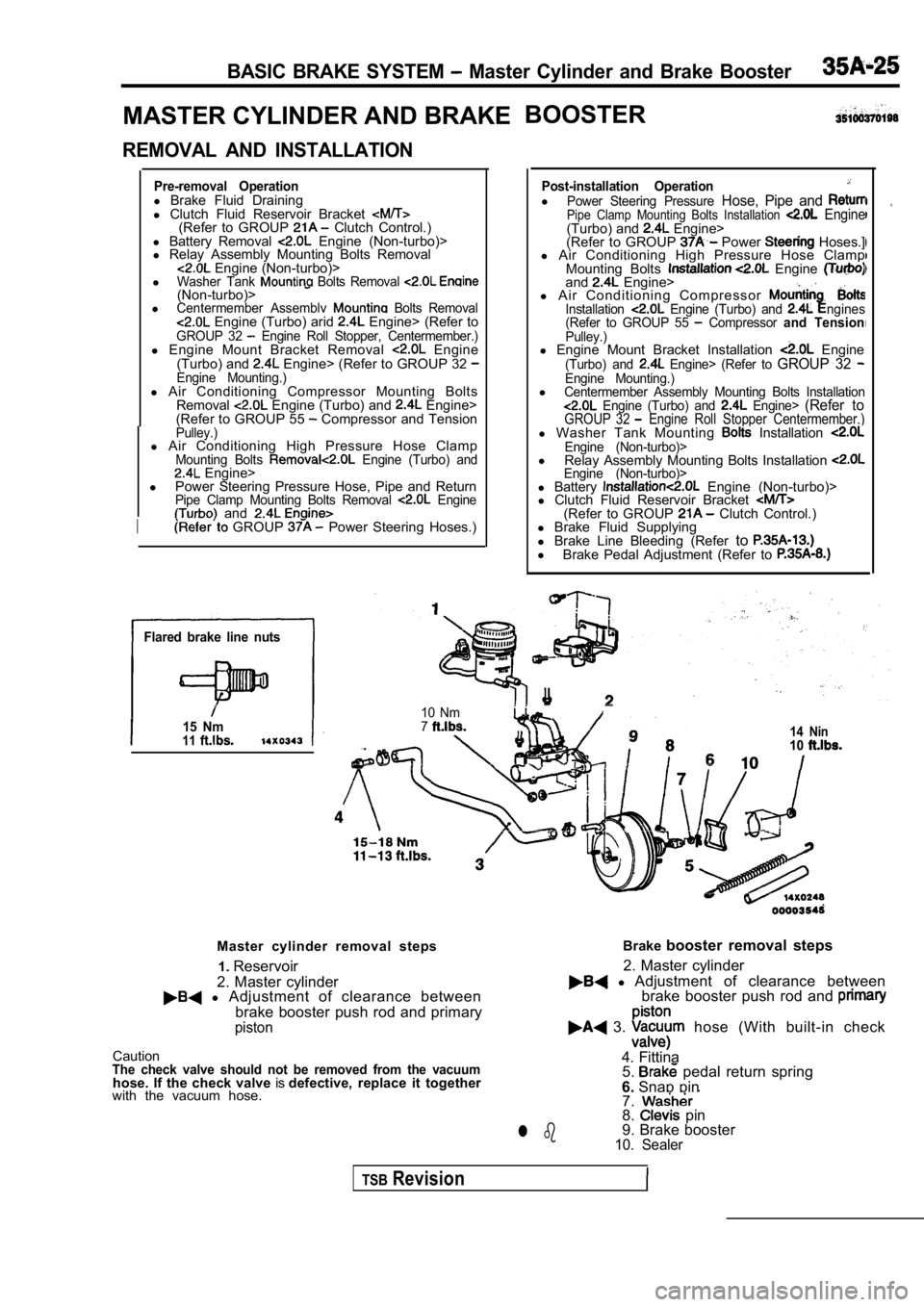
BASIC BRAKE SYSTEM Master Cylinder and Brake Booster
MASTER CYLINDER AND BRAKEBOOSTER
REMOVAL AND INSTALLATION
Pre-removal Operationl
Brake Fluid Draining
l Clutch Fluid Reservoir Bracket
(Refer to GROUP Clutch Control.)
l Battery Removal Engine (Non-turbo)>
l Relay Assembly Mounting Bolts Removal
Engine (Non-turbo)>
lWasher Tank Bolts Removal (Non-turbo)>lCentermember Assemblv Bolts Removal Engine (Turbo) arid Engine> (Refer toGROUP 32 Engine Roll Stopper, Centermember.)l Engine Mount Bracket Removal Engine
(Turbo) and Engine> (Refer to GROUP 32 Engine Mounting.)l Air Conditioning Compressor Mounting Bolts
Removal Engine (Turbo) and Engine>
(Refer to GROUP 55 Compressor and TensionPulley.)l Air Conditioning High Pressure Hose ClampMounting Bolts Engine (Turbo) and Engine>
l Power Steering Pressure Hose, Pipe and Return
Pipe Clamp Mounting Bolts Removal Engine and
I GROUP Power Steering Hoses.)
Flared brake line nuts
15 Nm11
Post-installation OperationlPower Steering Pressure Hose, Pipe and Pipe Clamp Mounting Bolts Installation Engine(Turbo) and Engine>
(Refer to GROUP Power Hoses.]
l Air Conditioning High Pressure Hose Clamp
Mounting Bolts
Engine and Engine>
l A i r C o n d i t i o n i n g C o m p r e s s o r
Installation Engine (Turbo) and ngines
(Refer to GROUP 55 Compressor and TensionPulley.)l Engine Mount Bracket Installation Engine(Turbo) and Engine> (Refer to GROUP 32 Engine Mounting.)lCentermember Assembly Mounting Bolts Installation Engine (Turbo) and Engine> (Refer toGROUP 32 Engine Roll Stopper Centermember.)l Washer Tank Mounting Installation Engine (Non-turbo)>l
Relay Assembly Mounting Bolts Installation Engine (Non-turbo)>l Battery Engine (Non-turbo)>
l Clutch Fluid Reservoir Bracket
(Refer to GROUP Clutch Control.)
l Brake Fluid Supplying
l Brake Line Bleeding (Refer to
l
Brake Pedal Adjustment (Refer to
I
10 Nm714 Nin10
Master cylinder removal steps
2. Master cylinder1.
Reservoir
l Adjustment of clearance between
brake booster push rod and primary
piston
CautionThe check valve should not be removed from the vacu umhose. If the check valve isdefective, replace it together
with the vacuum hose. Brake
booster removal steps
l Adjustment of clearance between
2. Master cylinder
brake booster push rod and
3. hose (With built-in check
4. Fittina 5.
pedal return spring
6. Snap pin
7.
8. pin
9. Brake booster
10. Sealerl b
TSBRevision
Page 1687 of 2103
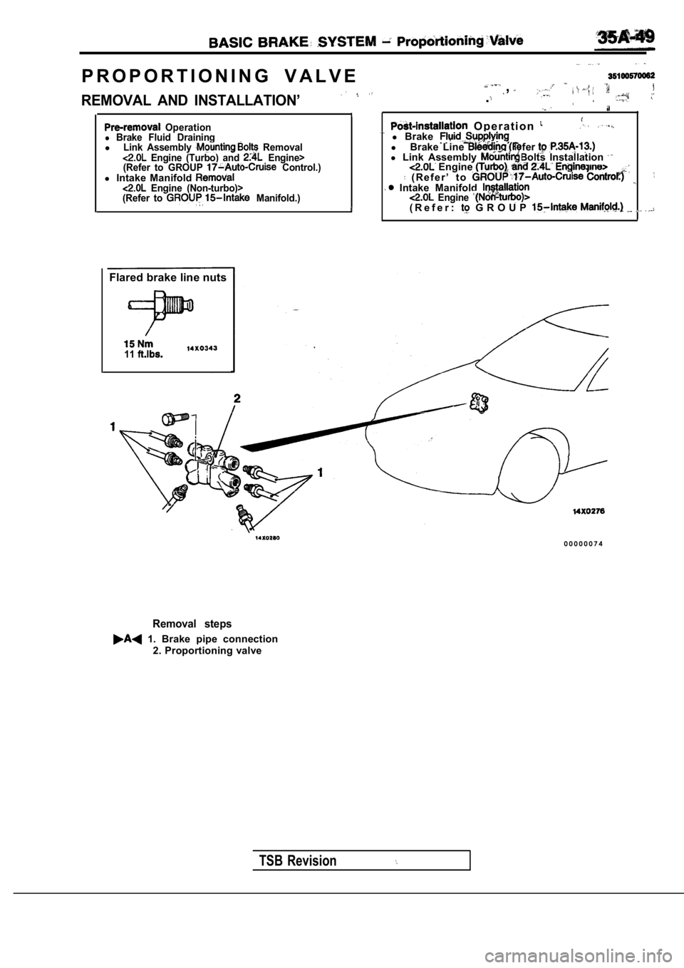
P R O P O R T I O N I N G V A L V E,
REMOVAL AND INSTALLATION’.
O p e r a t i o n Operationl Brake Fluid DrainingLink Assembly Removal l Brakel l Engine (Turbo) and Engine>Brake Line fer l
Link Assembly Bolts Installation (Refer to GROUP Control.) Engine l Intake Manifold ( R e f e r ’ t o Engine (Non-turbo)> Intake Manifold (Refer to Manifold.) Engine ( R e f e r : G R O U P
Flared brake line nuts
11
TSB Revision
Removal steps
1. Brake pipe connection
2. Proportioning valve
0 0 0 0 0 0 7 4