drain bolt MITSUBISHI SPYDER 1990 Service Owner's Manual
[x] Cancel search | Manufacturer: MITSUBISHI, Model Year: 1990, Model line: SPYDER, Model: MITSUBISHI SPYDER 1990Pages: 2103, PDF Size: 68.98 MB
Page 1722 of 2103
ABS
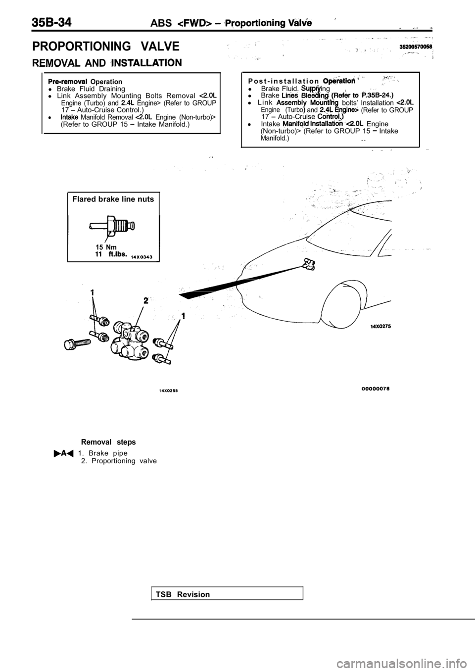
PROPORTIONING VALVE
REMOVAL AND
Operationl Brake Fluid Draining
l Link Assembly Mounting Bolts Removal
Engine (Turbo) and Engine> (Refer to GROUP17 Auto-Cruise Control.)l Manifold Removal Engine (Non-turbo)>(Refer to GROUP 15 Intake Manifold.)
Flared brake line nuts
15 Nm
P o s t - i n s t a l l a t i o nl Brake Fluid. ing
l Brake
l L i n kEngine (Turboandbolts’ Installation (Refer to GROUP17 Auto-Cruise l Intake Engine
(Non-turbo)> (Refer to GROUP 15 IntakeManifold.)
TSB Revision
Removal steps
1. Brake pipe
2. Proportioning valve
Page 1724 of 2103
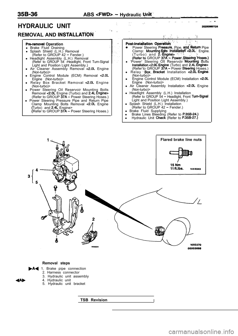
HYDRAULIC UNIT
ABS Hydraulic .
.
REMOVAL AND
.
Operationl Brake Fluid Draining
l Splash Shield (L.H.) Removal
(Refer to GROUP 42
Fender.)
l Headlight Assembly (L.H.) Removal
(Refer to GROUP 54 -Headlight, Front Turn-SignalLight and Position Light Assembly.)
l Air Cleaner Assembly Removal Engine(Non-turbo)>l Engine Control Module (ECM) Removal Engine (Non-turbo)>l R e l a y B o x B r a c k e t R e m o v a l E n g i n e(Non-turbo)>
Power Steering Pipe, Pipe
Clamp: Engine.( T u r b o ) a n d . GROUP l ‘Power‘ Steering Oil Reservoir Bolts (Turbo) and (Refer’to GROUP Power Hoses.)
l R e l a y Installation (Non-turbo)>l Engine Control Module (ECM) Installation Engine (Non-turbo)>l Air Cleaner Assembly Installation Engine(Non-turbo)>l Power Steering Oil Reservoir Mounting Bolts
Removal Engine (Turbo) and (Refer to GROUP Power Steering Hoses.)
l Power Steering Pressure Pipe and Return Pipe
Clamp Mounting Bolts Removal
EngineTurbo)and Engine>
Refer to GROUP Power Steering Hoses.) l
Headlight Assembly (L.H.) Installation
(Refer to GROUP 54 Headlight, Front Light and Position Light Assembly.)
l Splash Shield (L.H.) Installation
(Refer to GROUP 42
Fender.)
l Brake Fluid Supplying
l Brake Lines Bleeding (Refer to
lHydraulic Unit (Refer to
Flared brake line nuts
Removal steps
1. Brake pipe connection2.Harness connector
3. Hydraulic unit assembly
4. Hydraulic unit 5. Hydraulic unit bracket
TSB Revision
I
Page 1792 of 2103
STEERING Power Steering Gear.
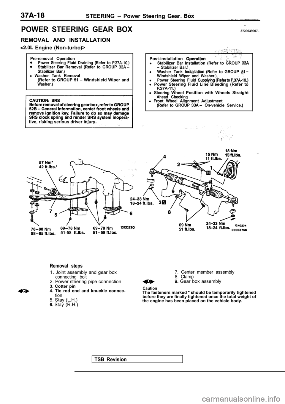
POWER STEERING GEAR BOX
REMOVAL AND INSTALLATION
Engine (Non-turbo)>
Pre-removal OperationPower Steering Fluid Draining (Refer to Stabilizer Bar Removal (Refer to GROUP Stabilizer Bar.)l Washer Tank Removal(Refer to GROUP 51 Windshield Wiper andWasher.)
tive, risking serious driver injury.
Nm Nm Nm51-58
3720039007~
TSB Revision
Removal steps
1. Joint assembly and gear boxconnecting bolt2. Power steering pipe connection
3. Cotter pin
4. Tie rod end and knuckle connec-
tion5. Stay (L.H.)
6. Stay (R.H.) Post-installation
lStabilizer Bar Installation (Refer to GROUP Stabilizer Bar.)lWasher Tank (Refer to GROUP Windshield Wiper and Washer.),lPower Steering Fluid l
Power Steering Fluid Line Bleeding (Refer to
l Wheel Position with Wheels StraightAhead Checkingl Front Wheel Alignment Adjustment
(Refer to GROUP On-vehicle Service.)
6951
7. Center member assembly
8. Clamp
Gear box assembly
CautionThe fasteners marked should be temporarily tightened
before they are finally tightened once the total we ight of
the engine has been placed on the vehicle body.
Page 1918 of 2103
BODY Electric Convertible Top
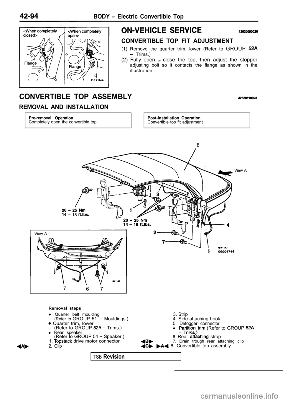
CONVERTIBLE TOP FIT ADJUSTMENT
(1) Remove the quarter trim, lower (Refer to GROUP
Trims.)
(2) Fully open orclose the top, then adjust the stopper
adjusting bolt so it contacts the flange as shown in the
illustration.
CONVERTIBLE TOP ASSEMBLY
REMOVAL AND INSTALLATION
Pre-removal OperationCompletely open the convertible top.Post-installation OperationConvertible top fit adjustment
8
View A
18
View A
76 7
5
Removal steps
3. Strip
l
Quarter belt moulding
(Refer to GROUP 51
Mouldings.) Quarter trim, lower
(Refer to GROUP Trims.)l Rear speaker(Refer to GROUP 54 Speaker.)
1. drive motor connector
2. Clip
4. Side attaching hook5. Defogger connectorl (Refer to GROUP
6. Rear strap
7. Drain trough rear attaching clip
8. Convertible top assembly
TSBRevision
Page 1919 of 2103
BODY Electric Convertible
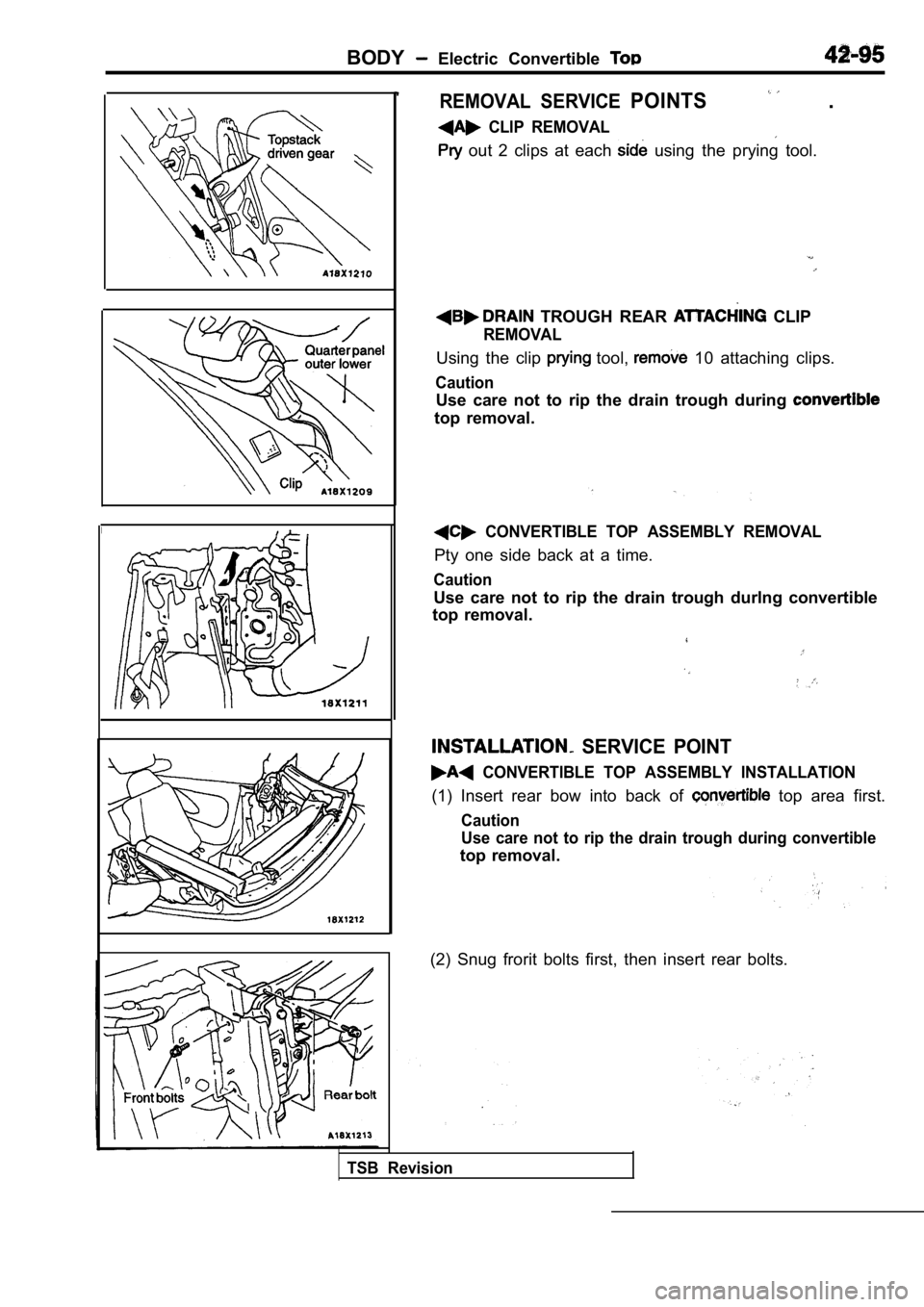
REMOVAL SERVICE POINTS .
CLIP REMOVAL
out 2 clips at each using the prying tool.
TROUGH REAR CLIP
REMOVAL
Using the clip tool, 10 attaching clips.
Caution
Use care not to rip the drain trough during
top removal.
CONVERTIBLE TOP ASSEMBLY REMOVAL
Pty one side back at a time.
Caution
Use care not to rip the drain trough durlng convertible
top removal.
TSB Revision
SERVICE POINT
CONVERTIBLE TOP ASSEMBLY INSTALLATION
(1) Insert rear bow into back of top area first.
Caution
Use care not to rip the drain trough during convert ible
top removal.
(2) Snug frorit bolts first, then insert rear bolts .
Page 2072 of 2103
HEATER, AIR
AND VENTILATIONCompressor’ and Pulley Engine (Turbo) and
INSTALLATION
COMPRESSOR INSTALLATION
If a new compressor is installed, first adjust the amount of
oil according to the procedures described below, an d then
install the compressor.
(1)Measure the amount (x of oil within the
removed compressor.
(2) Drain (from the new compressor) the amount of o il calcu-
lated according to the following formula, and then install
then new compressor.
New compressor oil amount
170
(1) (y indicates the amount of oil in the
refrigerant line, the condenser, the evaporator
. .
R E M O V A L S E R V I C E P O I N T S
FLUID
Disconnect the brake fluid level sensor connector a nd, remove
the brake fluid reservoir from the compressor
the hose still attached.
NOTE
Place the removed brake fluid reservoir in where
it will not be a hindrance when removing and instal ling the
A/C compressor, and tie it
cord.
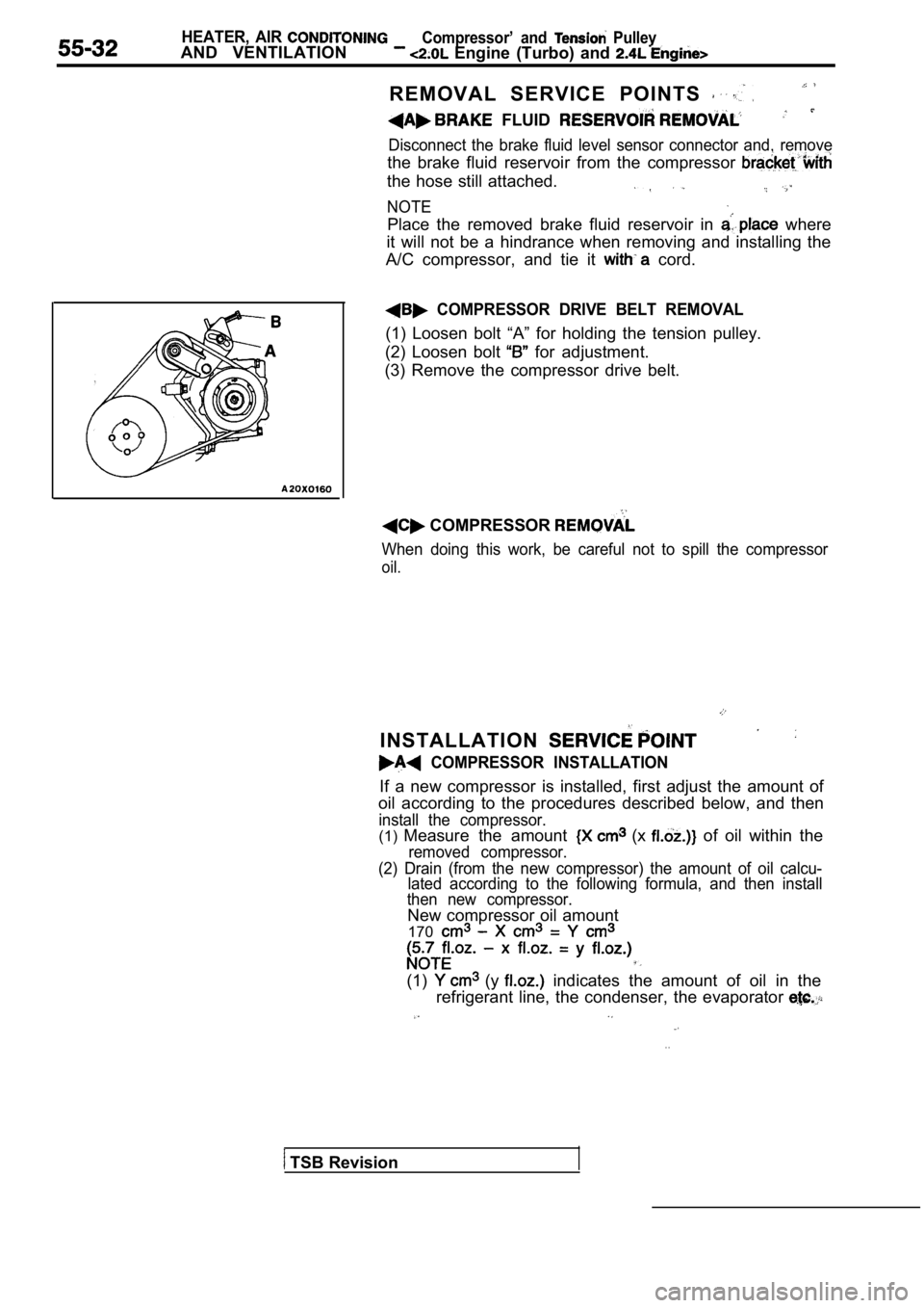
COMPRESSOR DRIVE BELT REMOVAL
(1) Loosen bolt “A” for holding the tension pulley.
(2) Loosen bolt
for adjustment.
(3) Remove the compressor drive belt.
COMPRESSOR
When doing this work, be careful not to spill the c ompressor
oil.
TSB Revision
Page 2079 of 2103
Compressor
AND VENTILATION,
REMOVAL SERVICE
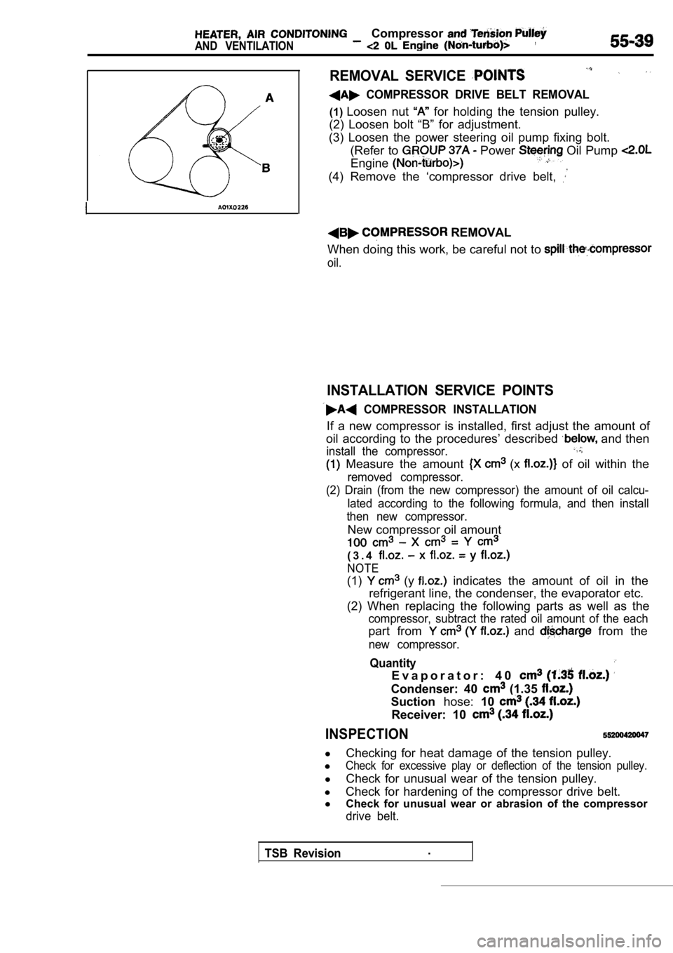
COMPRESSOR DRIVE BELT REMOVAL
(1)Loosen nut for holding the tension pulley.
(2) Loosen bolt “B” for adjustment.
(3) Loosen the power steering oil pump fixing bolt. (Refer to
Power Oil Pump
Engine
(4) Remove the ‘compressor drive belt,
REMOVAL
When doing this work, be careful not to
oil.
INSTALLATION SERVICE POINTS
COMPRESSOR INSTALLATION
If a new compressor is installed, first adjust the amount of
oil according to the procedures’ described
and then
install the compressor.
Measure the amount (x of oil within the
removed compressor.
(2) Drain (from the new compressor) the amount of o il calcu-
lated according to the following formula, and then install
then new compressor.
New compressor oil amount
( 3 . 4
NOTE
(1) (y indicates the amount of oil in the
refrigerant line, the condenser, the evaporator etc .
(2) When replacing the following parts as well as t he
compressor, subtract the rated oil amount of the each
part from and from the
new compressor.
Quantity
E v a p o r a t o r : 4 0
Condenser: 40 (1.35
Suctionhose:10
Receiver: 10
INSPECTION
l
Checking for heat damage of the tension pulley.
l
Check for excessive play or deflection of the tensi on pulley.
l
Check for unusual wear of the tension pulley.
l Check for hardening of the compressor drive belt.
l Check for unusual wear or abrasion of the compresso r
drive belt.
TSB Revision.