relay MITSUBISHI SPYDER 1990 Service User Guide
[x] Cancel search | Manufacturer: MITSUBISHI, Model Year: 1990, Model line: SPYDER, Model: MITSUBISHI SPYDER 1990Pages: 2103, PDF Size: 68.98 MB
Page 397 of 2103
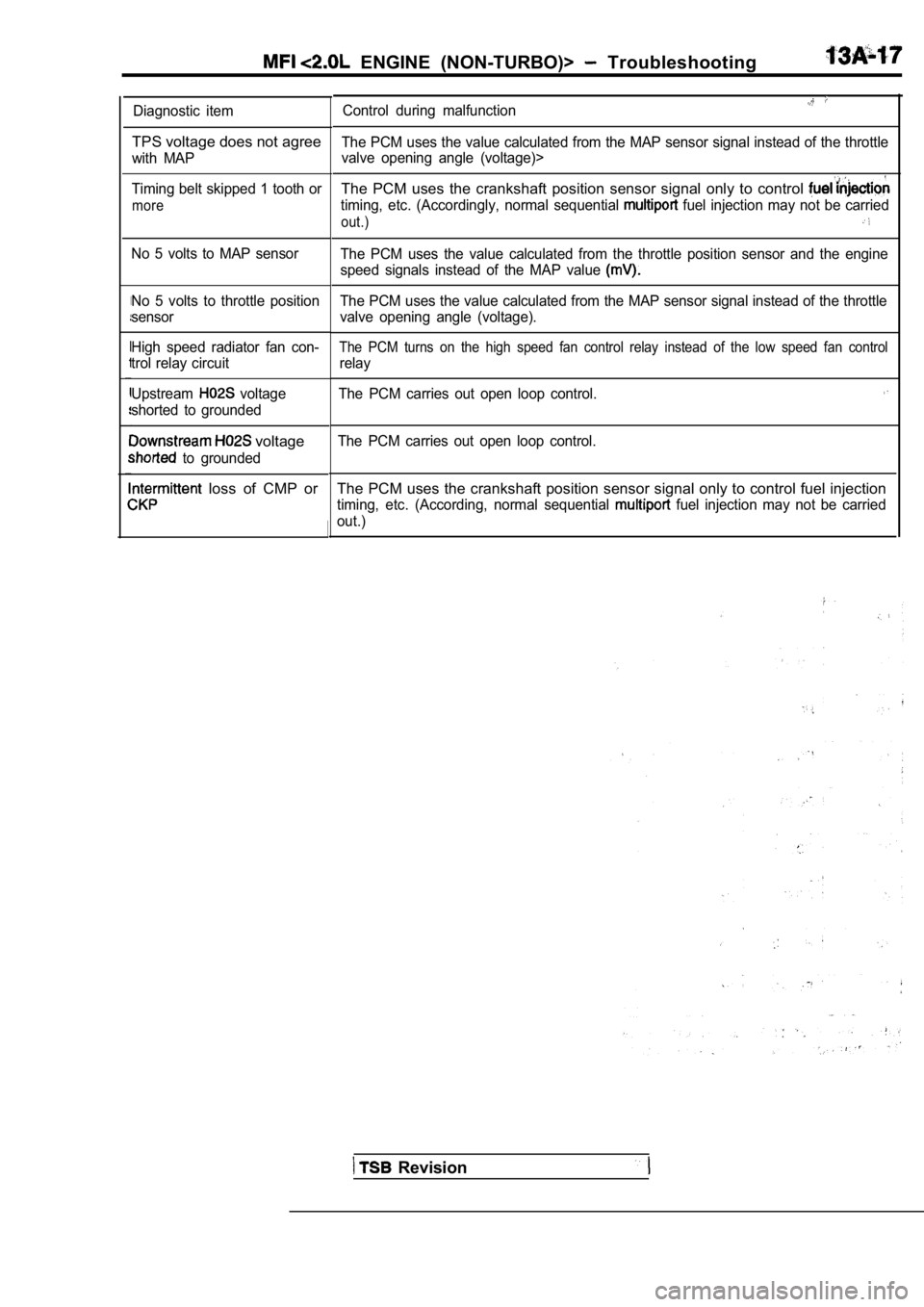
ENGINE (NON-TURBO)> Troubleshooting
Diagnostic item
TPS voltage does not agree
with MAP
Timing belt skipped 1 tooth or
more
No 5 volts to MAP sensor
No 5 volts to throttle position
sensor
High speed radiator fan con-
trol relay circuit
Upstream
voltage
shorted to grounded
voltage
to grounded
loss of CMP or
Control during malfunction
The PCM uses the value calculated from the MAP sens or signal instead of the throttle
valve opening angle (voltage)>
The PCM uses the crankshaft position sensor signal only to control
timing, etc. (Accordingly, normal sequential fuel injection may not be carried
out.)
The PCM uses the value calculated from the throttle position sensor and the engine
speed signals instead of the MAP value
The PCM uses the value calculated from the MAP sens or signal instead of the throttle
valve opening angle (voltage).
The PCM turns on the high speed fan control relay i nstead of the low speed fan control
relay
The PCM carries out open loop control.
The PCM carries out open loop control.
The PCM uses the crankshaft position sensor signal only to control fuel injection
timing, etc. (According, normal sequential fuel injection may not be carried
out.)
Revision
Page 398 of 2103
ENGINE (NON-TURBO)> Troubleshooting
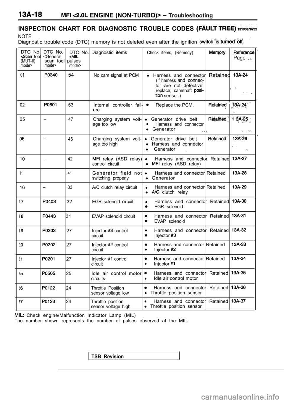
INSPECTION CHART FOR DIAGNOSTIC TROUBLE CODES
NOTE
Diagnostic trouble code (DTC) memory is not deleted even after the ignition
DTC No. DTC No.
DTC No. Diagnostic itemsCheck items, (Remedy) tool
mode>
mode>
01 54No cam signal at PCMl Harness and connector Retained
(If harness and connec-
tor are not defective,
replace; camshaft ,
sensor.) ,
02 53
Internal controller fail- Replace the PCM.,
. .
0547
46
Charging system volt- l Generator drive belt
age too lowlHarness and connector
l Generator. . ,
Charging system volt- l Generator drive belt
age too highl Harness and connector
l Generator
1042
1 141
1633
relay (ASD relay) lHarness and connector Retained
control circuitl relay (ASD relay)
G e n e r a t o r f i e l d n o t lHarness and connector Retained
switching properlyl Generator
A/C clutch relay circuitlHarness and connector Retained
l clutch relay
32
31
27
27
27
25
24
24
EGR solenoid circuitlHarness and connector Retained
EGR solenoid
EVAP solenoid circuit
Harness and connector Retained
EVAP solenoid
Injector
controllHarness and connector Retained
circuitInjector
Injector controlHarness and connector Retained
circuitlInjector
Injector controlHarness and connector Retained
circuitlInjector
Idle air control motor Harness and connector Retained
circuitslIdle air control motor
Throttle PositionHarness and connector Retained
sensor voltage lowl Throttle position sensor
Throttle positionlHarness and connector Retained
sensor voltage highl Throttle position sensor
TSB Revision
Check engine/Malfunction Indicator Lamp (MIL)
The number shown represents the number of pulses ob served at the MIL.
Page 399 of 2103
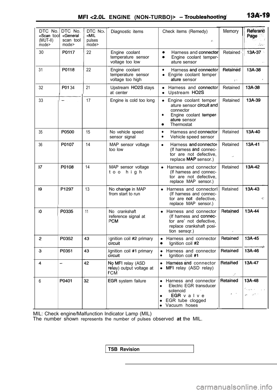
ENGINE (NON-TURBO)>
1MemoryDiagnostic itemsCheck items (Remedy)
Engine coolantHarness and
temperature sensorEngine coolant temper
voltage too low
ature sensor
Engine coolantlHarness
temperature sensorl Engirie coolant temper
voltage too high sensor
Upstream staysl Harness and
at centerl Upstream
Engine is cold too longl Engine coolant temper
ature sensor
connectorlEngine coolant
sensor
Thermostat
No vehicle speed
lHarness and
sensor signallVehicle speed sensor
MAP sensor voltagelHarness
too low (If harness connec-
tor are not defective, replace
sensor.)
MAP sensor voltagel Harness and connector
t o o h i g h
(If harness and connec-
tor are not defective,
replace MAP sensor.)
No
in MAPl Harness and connector
from start to run (If harness and connec-
tor are defective,
replace MAP sensor.)
No crankshaftl Harness and connector
reference signal at (If harness and
tor are’ not defective,
replace crankshaft posi-
tion sensqr.)
gnition coil
primaryl Harness and connector
Ignition coil
gnition coil primaryl Harness and connectorlIgnition coil
relay (ASDl connector
ay) output voltage atl relay (ASD relay)
‘CM
system failurel Harness and connector
lElectric EGR transducer
solenoid
l v a l v e
l EGR tube clogged
l Vacuum hoses
DTC NC
pulses
mode>
DTC No. DTC No. tool (MUT-II)scan toolmode>mode>
30
31
32 34
1
I
I
I
I
Retained22
22
,
I
I
I
Retained
Retained
21
17
15
14
14
33
35Retained
36Retained
Retained
13Retained
11
6
MIL: Check engine/Malfunction Indicator Lamp (MIL)
The number shown represents the number of pulses observedatthe MIL.
TSB Revision
Page 400 of 2103
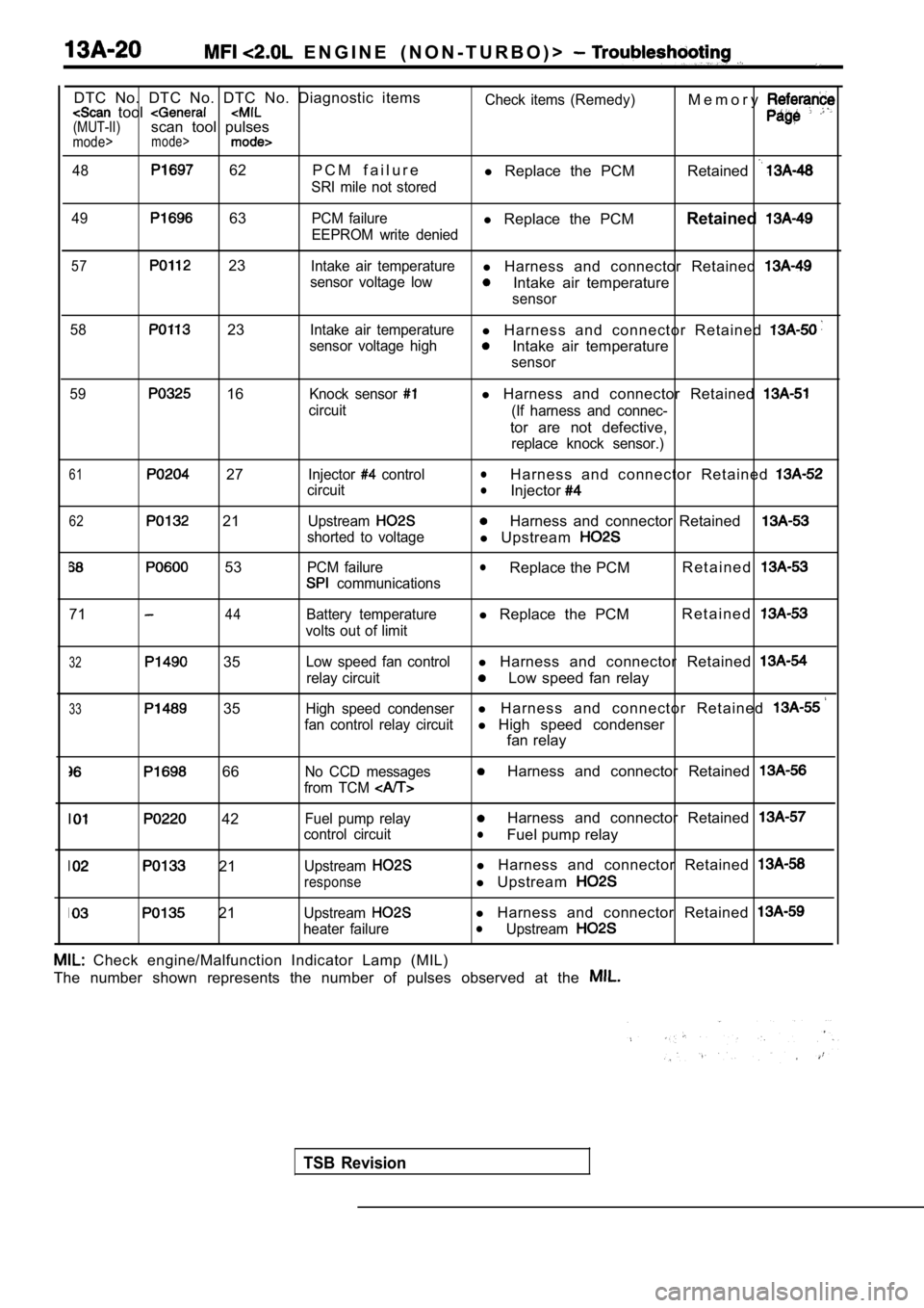
E N G I N E ( N O N - T U R B O ) >
DTC No. DTC No. DTC No. Diagnostic items tool (MUT-II)scan tool pulsesmode>mode>
48 62 P C M f a i l u r e
SRI mile not storedCheck items (Remedy)
l
Replace the PCM M e m o r yRetained
49 63PCM failurel
Replace the PCM Retained
EEPROM write denied
57 23Intake air temperaturel Harness and connector Retained
sensor voltage lowIntake air temperature
sensor
58
23Intake air temperaturel H a r n e s s a n d c o n n e c t o r R e t a i n e d
sensor voltage highIntake air temperature
sensor
59
16Knock sensor
circuit
l Harness and connector Retained
(If harness and connec-
tor are not defective,
replace knock sensor.)
61 27
62 21
53
Injector control
circuit
Upstream
shorted to voltage
PCM failure
communications
lH a r n e s s a n d c o n n e c t o r R e t a i n e d lInjector
Harness and connector Retained
l Upstream
lReplace the PCM R e t a i n e d
7144Battery temperature
volts out of limitl Replace the PCM R e t a i n e d
32 35
33 35
Low speed fan controll
Harness and connector Retained
relay circuitLow speed fan relay
High speed condenserl H a r n e s s a n d c o n n e c t o r R e t a i n e d
fan control relay circuitl High speed condenser
fan relay
66No CCD messages
from TCM Harness and connector Retained
42
21
21
Fuel pump relay
control circuit
Upstream
response
Upstream
heater failure
Harness and connector Retained
lFuel pump relay
l Harness and connector Retained
l Upstream
l Harness and connector Retained lUpstream
Check engine/Malfunction Indicator Lamp (MIL)
The number shown represents the number of pulses ob served at the
TSB Revision
Page 403 of 2103
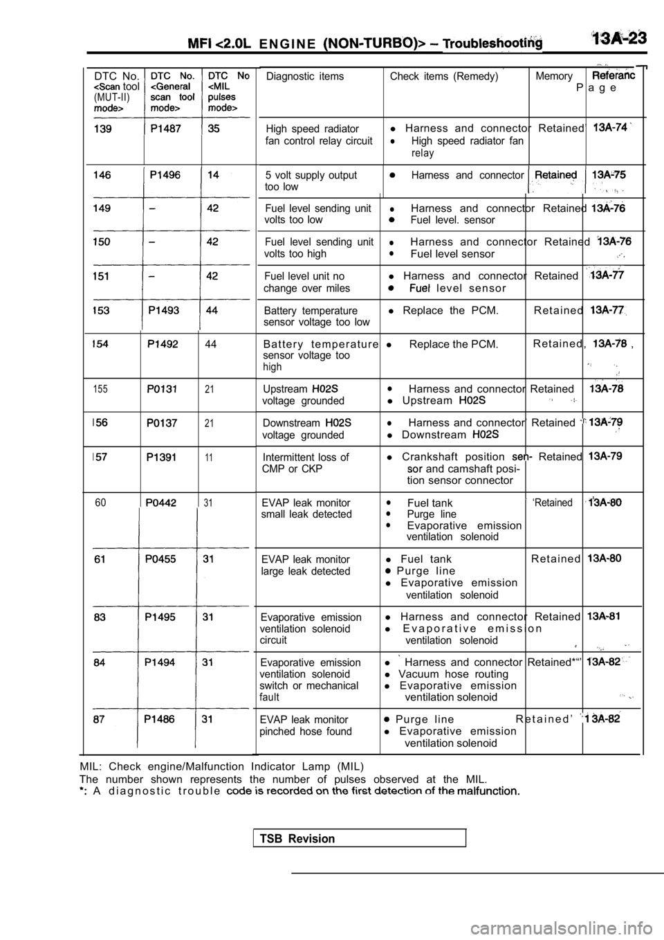
E N G I N E
DTC No. tool(MUT-II)
155
44
21
21
11
6031
Diagnostic items Check items (Remedy) Memory
P a g e
High speed radiatorl Harness and connector Retained’
fan control relay circuitlHigh speed radiator fan
relay
5 volt supply outputHarness and connector
too low
Fuel level sending unitlHarness and connector Retained
volts too lowFuel level. sensor
Fuel level sending unit
lHarness and connector Retained
volts too highlFuel level sensor
Fuel level unit nol Harness and connector Retained
change over miles l e v e l s e n s o r
Battery temperaturel Replace the PCM. R e t a i n e d
sensor voltage too low
B a t t e r y t e m p e r a t u r e lReplace the PCM. R e t a i n e d , ,
sensor voltage too
high
UpstreamlHarness and connector Retained
voltage groundedl
Upstream
DownstreamlHarness and connector’ Retained
voltage groundedl Downstream
Intermittent loss of
CMP or CKPl Crankshaft position Retained
and camshaft posi-
tion sensor connector
EVAP leak monitor
small leak detectedlFuel tank ‘RetainedlPurge linelEvaporative emissionventilation solenoid
EVAP leak monitor
large leak detected
l Fuel tank R e t a i n e d
P u r g e l i n e
l Evaporative emission
ventilation solenoid
Evaporative emission
ventilation solenoid
circuit
Evaporative emission
ventilation solenoid
switch or mechanical
fault
l Harness and connector Retained
l E v a p o r a t i v e e m i s s i o n
ventilation solenoid
l Harness and connector Retained*“’
l Vacuum hose routing
l Evaporative emission
ventilation solenoid
EVAP leak monitor
pinched hose found P u r g e l i n e R e t a i n e d ’
l
Evaporative emission
ventilation solenoid
MIL: Check engine/Malfunction Indicator Lamp (MIL)
The number shown represents the number of pulses ob served at the MIL.
A d i a g n o s t i c t r o u b l e
TSB Revision
Page 405 of 2103
![MITSUBISHI SPYDER 1990 Service User Guide ENGINE (NON-TURBO)>
C h a r g i n g T o o
47
[Comment]
Background
The PCM tries to maintain charging system voltage of between and 15 volts.
l This code indicates:
The batte](/img/19/57345/w960_57345-404.png "MITSUBISHI SPYDER 1990 Service User Guide ENGINE (NON-TURBO)>
C h a r g i n g T o o
47
[Comment]
Background
The PCM tries to maintain charging system voltage of between and 15 volts.
l This code indicates:
The batte")
ENGINE (NON-TURBO)>
C h a r g i n g T o o
47
[Comment]
Background
The PCM tries to maintain charging system voltage of between and 15 volts.
l This code indicates:
The battery voltage input is below the target charg ing voltage during engine
andNo significant change in voltage has been detected during active testing of the generator
output circuit.
Range of Check
lEngine speed: or more for approx. one minutelBattery positive voltage is at least 1 lower than the target charging voltage for approx.60 seconds.Set ConditionlBattery positive voltage does not change even if th e generator field current is cut off.
lDefects in generator or adjustmentl High resistance generatorl High between battery and
generator ground
l PCM
Check that the generator drive belt is properly in stalled. Repair
NG Measure the voltage between the generator terminal and the battery positive terminal. Engine: 1600 Headlight: High beam ON)
OK: Less than
Check the harness wire and terminal generator terminal and battery necessary.
NGMeasure the voltage between the generator body and battery Check the generator grounded line: neoative terminal. Engine: 1600 Headlight: High beam ON)
OK: Less than 0.5
OK
Measure at the generator lDisconnect the connector, and measure at the harnes s side.
SCAN TOOL Actuator test 10
relay (ASD relay) isturnedonandoff everyapprox. l Voltage between 1 and ground
[Measure when the relay (ASD relay) is turned on.]
OK: Battery positive voltage
NG Check the wire between generator relay
(ASD relay) connector. Repair, if necessary.
OK
Check the harness wire NG Repair connector.I
OK NG
SCAN TOOL SENSOR READ TEST (Data list) Check the harness wire between the PCM and the bat tery 10 Battery voltage as the ignition switch. Repair, if necessary.OK: indicated on the scan tool and actual positive
Check trouble symptom.
TSB RevisionI
Page 407 of 2103
![MITSUBISHI SPYDER 1990 Service User Guide Scan tool 10
Code
No.General scan tool r e l a y r e l a y )
42
[Comment]
Background
lThe relay (ASD relay) controls the battery voltage sup plied to the fuel injectors, ign](/img/19/57345/w960_57345-406.png "MITSUBISHI SPYDER 1990 Service User Guide Scan tool 10
Code
No.General scan tool r e l a y r e l a y )
42
[Comment]
Background
lThe relay (ASD relay) controls the battery voltage sup plied to the fuel injectors, ign")
Scan tool 10
Code
No.General scan tool r e l a y r e l a y )
42
[Comment]
Background
lThe relay (ASD relay) controls the battery voltage sup plied to the fuel injectors, ignitioncoils, and generator.
l The PCM provides a ground path for the relay (ASD relay).
l This DTC indicates an open or short-circuit conditi on in the control circuit.
Range of Check
l Battery voltage:
or more
l Ignition switch: ON
Set Condition
l Open or short circuit is detected in the
relay (ASD relay) for 3 seconds. l
Relay coil open or shorted
l relay shortedl circuit in
Check the relay (ASD relay) (Refer to
OK
NG Replace
Measure at the
relay (ASD relay) connector lDisconnect the connector, and measure at the harnes s side.
l Voltage between 6 and ground
OK: Battery positive voltage
OK
connector and the battery., Repair, if necessary.
N G
Repair ,
OK .
Check trouble symptom.
Check the harness wi
relay)
OK
NG Repair
Replace the PCM.
Revision
Page 408 of 2103
![MITSUBISHI SPYDER 1990 Service User Guide (NON-TURBO)> Troubleshooting
Scan tool 11
General scan tool G e n e r a t o r F i e l d N o t S w i t c h i n g
.
41
[Comment]Background
Properly
.
l Field driver circuit open](/img/19/57345/w960_57345-407.png "MITSUBISHI SPYDER 1990 Service User Guide (NON-TURBO)> Troubleshooting
Scan tool 11
General scan tool G e n e r a t o r F i e l d N o t S w i t c h i n g
.
41
[Comment]Background
Properly
.
l Field driver circuit open")
(NON-TURBO)> Troubleshooting
Scan tool 11
General scan tool G e n e r a t o r F i e l d N o t S w i t c h i n g
.
41
[Comment]Background
Properly
.
l Field driver circuit open or
l The PCM receives generator field input.lBattery voltage is supplied to the generator throug h the relay relay).
Range of Check
l Ignition switch: ON
l
relay (ASD relay): ON
Set Condition
l Open or short circuit is detected in the generator field control circuit.l
Generator internal o p en o r
l PCM failed ,
SCAN TOOL Actuator test
10 relay (ASD relay) Repair the relay relay) related
OK: The relay operating sound can be heard
OK
Measure at the generator connector lDisconnect the connector, and measure at the harnes s side.
SCAN TOOL Actuator test 10
relay (ASD relay) relay is turned on 1 l Voltage between 1 and ground
[Measure with the relay (ASD relay) on]
OK: Battery positive voltage
NG Check the harness wire the and relay) connector. Repair,’ if
NGMeasure at the generator connector Disconnect the connector and measure at the compone nt side. Repair the generator, and replace if necessary ll Continuity between 2 and generator body
OK: No continuity
OKNGCheck the harness wire between the PCM and the gene rator Repairconnector.
OK
Check the following connectors:
Repair
Check trouble symptom.
NG
Repair the generator, and replace if necessary.I
Page 409 of 2103
![MITSUBISHI SPYDER 1990 Service User Guide Scan tool 16
General scan tool A/C Clutch Relay Circuit ,.
33
[Comment]Coinpressor clutch relay shortedBackgroundl control circuit defectivel The PCM provides a switched groun](/img/19/57345/w960_57345-408.png "MITSUBISHI SPYDER 1990 Service User Guide Scan tool 16
General scan tool A/C Clutch Relay Circuit ,.
33
[Comment]Coinpressor clutch relay shortedBackgroundl control circuit defectivel The PCM provides a switched groun")
Scan tool 16
General scan tool A/C Clutch Relay Circuit ,.
33
[Comment]Coinpressor clutch relay shortedBackgroundl control circuit defectivel The PCM provides a switched ground to the clutch relay.
l circuit driver in PCMlThe PCM can prevent operation of the clutch in selected situations such as duringwide-open or for a period at start-up.l This DTC indicates an open or short-circuit conditi on in the circuit.Range of Checkl Ignition ONl Battery voltage: or morel 30 seconds or more after starting engineSet ConditionlOpen or short circuit is detected in the A/C clutch relay control circuit for 3 seconds.
N G relay. Replace
. .
. 55 On-vehicle Service) me (Refer to GROUF
OK
Measure at the PCM connectors and lDisconnect the connector, and measure at the harnes s side.
l Voltage between 36 and ground, and 64 and ground
(Ignition switch: ON)
switch: ON)
OK: Battery positive
l Connect a jumper wire between and the ground.
(Ignition switch: ON)
(A/C switch: ON)
OK:
compressor clutch is turned on
N G
Check the system (Refer to GROUP 55 Troubleshooting) Check trouble symptom.
NG
Replace the . ,
I ,
TSB Revision
Page 412 of 2103
![MITSUBISHI SPYDER 1990 Service User Guide ENGINE
Scan tool 19
Injector Control Circuit.Probable cause,
MIL 27
[Comment]
Backgroundl Open or shorted injector control
l Grounds for the injector circuits are provided by](/img/19/57345/w960_57345-411.png "MITSUBISHI SPYDER 1990 Service User Guide ENGINE
Scan tool 19
Injector Control Circuit.Probable cause,
MIL 27
[Comment]
Backgroundl Open or shorted injector control
l Grounds for the injector circuits are provided by")
ENGINE
Scan tool 19
Injector Control Circuit.Probable cause,
MIL 27
[Comment]
Backgroundl Open or shorted injector control
l Grounds for the injector circuits are provided by t he PCM.l i n j e c t o r
l Battery power is provided through the
relay (ASD relay) l
Open (ASD) supply l Driver in PCM failed lThis DTC is set if an open or short-circuit conditi on is detected in the control circuit for
the individual injector.
,Range of Checkl Battery voltage: or morel relay (ASD relay): ONl Engine: 3000 or lessSet Condition force is not detected for 3 seconds immediately af ter injectors
OK
NG
Measure at the injector connector Check the following connectors: lDisconnect the connector, and measure at the harnes s side.
SCAN TOOL Actuator test
10 relay (ASD relay) relay (ASD relay) is turned on and off every appro x. l Voltaae between 2 and around with the (ASD relay) on]
OK: Battery positive voltage Check the harness wire between the relay, (ASD and
the injector connector. Repair, if necessary.
Measure at the PCM connector
lDisconnect the connector and measure at the harness side.lDisconnect PCM connector and short terminal (67) of
the harness-side connector to ground.
l Voltage between 7 and ground
OK: Battery positive voltage Check the
between PCM and injector connector. Repair, if
OK
Check Repair
OK
Check trouble symptom.
NG
Replace the PCM.
Revision