brake MITSUBISHI SPYDER 1990 Service Repair Manual
[x] Cancel search | Manufacturer: MITSUBISHI, Model Year: 1990, Model line: SPYDER, Model: MITSUBISHI SPYDER 1990Pages: 2103, PDF Size: 68.98 MB
Page 1731 of 2103
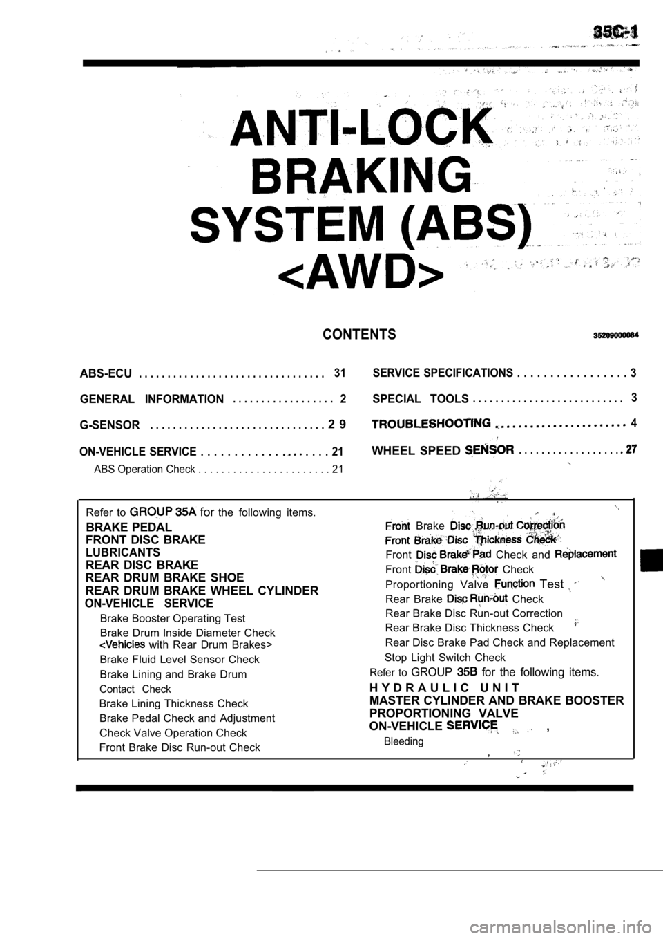
CONTENTS
ABS-ECU. . . . . . . . . . . . . . . . . . . . . . . . . . . . . . . . .31 SERVICE SPECIFICATIONS . . . . . . . . . . . . . . . . . 3
GENERAL INFORMATION2SPECIAL TOOLS. . . . . . . . . . . . . . . . . . . . . . . . . . .3. . . . . . . . . . . . . . . . . .
G-SENSOR2 9. . . . . . . . . . . . . . . . . . . . . . . . . . . . . . .4
ON-VEHICLE SERVICE . . . . . . . . . . . .
. . . . 21WHEEL SPEED . . . . . . . . . . . . . . . . . .
ABS Operation Check . . . . . . . . . . . . . . . . . . . . . . . 21
Refer to for the following items.
BRAKE PEDAL
FRONT DISC BRAKE
LUBRICANTS
REAR DISC BRAKE
REAR DRUM BRAKE SHOE
REAR DRUM BRAKE WHEEL CYLINDER
ON-VEHICLE SERVICE
Brake Booster Operating Test
Brake Drum Inside Diameter Check
with Rear Drum Brakes>
Brake Fluid Level Sensor Check
Brake Lining and Brake Drum
Contact Check
Brake Lining Thickness Check Brake Pedal Check and Adjustment
Check Valve Operation Check
Front Brake Disc Run-out Check
Brake
Front Check and
Front Check
Proportioning Valve Test
Rear Brake Check
Rear Brake Disc Run-out Correction
Rear Brake Disc Thickness Check
Rear Disc Brake Pad Check and Replacement
Stop Light Switch Check
Refer to GROUP for the following items.
H Y D R A U L I C U N I T
MASTER CYLINDER AND BRAKE BOOSTER
PROPORTIONING VALVE
ON-VEHICLE
,
Bleeding,
Page 1734 of 2103
ABS
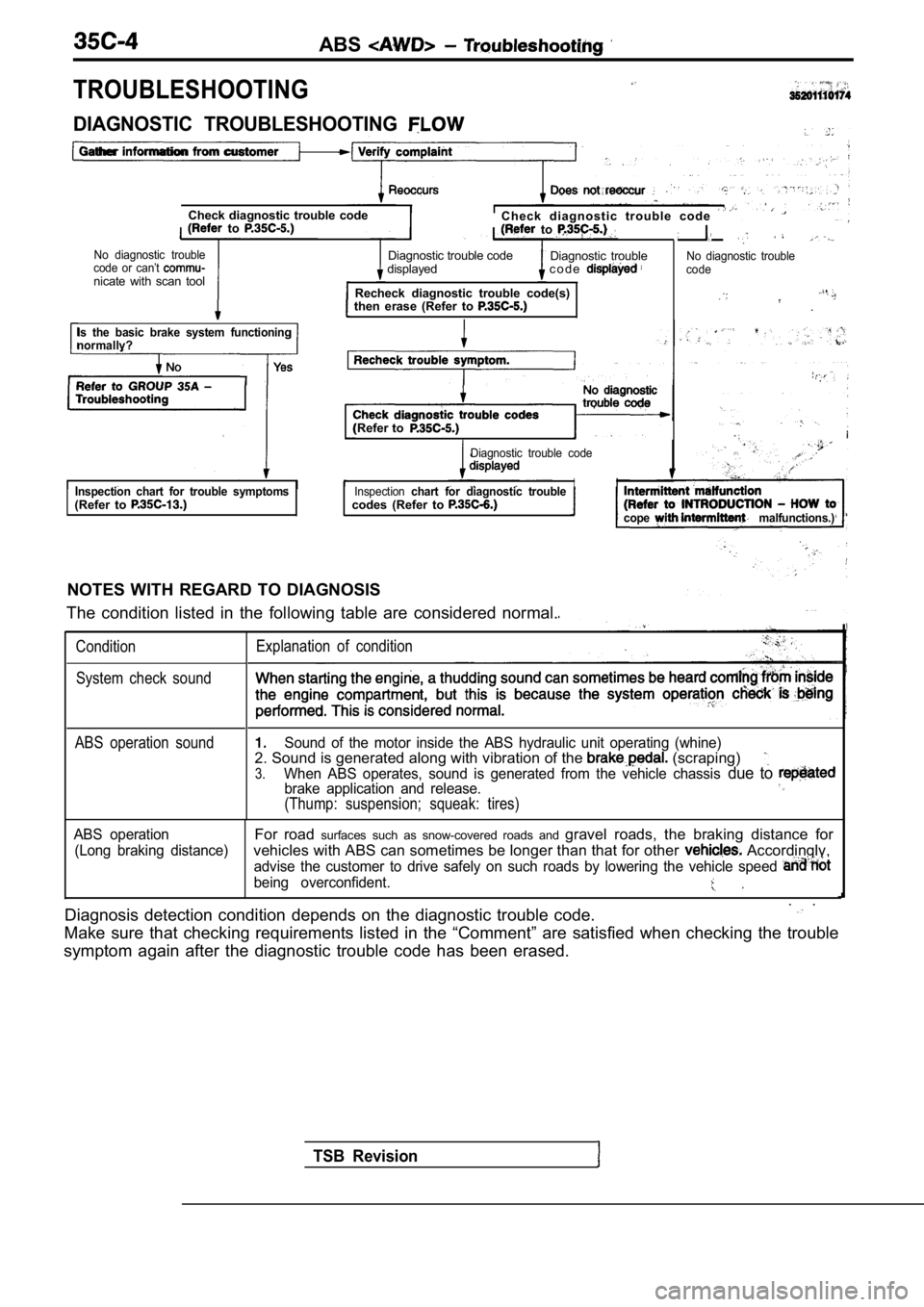
TROUBLESHOOTING
Check diagnostic trouble codeC h e c k d i a g n o s t i c t r o u b l e c o d e to to
No diagnostic troubleDiagnostic trouble codecode or can’t Diagnostic trouble
displayed c o d e
nicate with scan tool Recheck diagnostic trouble code(s)
then erase (Refer to
No diagnostic trouble
code
.
DIAGNOSTIC TROUBLESHOOTING
Gather information from customer
Is the basic brake system functioning
normallv?
(Refer to
Diagnostic trouble code
Inspection chart for trouble symptoms(Refer to Inspectionchart for diagnostic troubleII
codes (Refer to
cope malfunctions.)
NOTES WITH REGARD TO DIAGNOSIS
The condition listed in the following table are con sidered normal.
ConditionExplanation of condition
System check sound
TSB Revision
ABS operation soundSound of the motor inside the ABS hydraulic unit op erating (whine)2. Sound is generated along with vibration of the (scraping)
3.When ABS operates, sound is generated from the vehi cle chassis due to brake application and release.
(Thump: suspension; squeak: tires)
ABS operationFor road surfaces such as snow-covered roads and gravel roads, the braking distance for
(Long braking distance)vehicles with ABS can sometimes be longer than that for other Accordingly,
advise the customer to drive safely on such roads by lowering the vehicle speed
being overconfident.
. .
Diagnosis detection condition depends on the diagno stic trouble code.
Make sure that checking requirements listed in the “Comment” are satisfied when checking the trouble
symptom again after the diagnostic trouble code has been erased.
Page 1739 of 2103
![MITSUBISHI SPYDER 1990 Service Repair Manual ABSTroubleshooting.
Code No. 22 Stop switch system
[Comment]The ABS-ECU outputs this diagnostic trouble code in the following cases.Stop light switch remains on for more than 1](/img/19/57345/w960_57345-1738.png "MITSUBISHI SPYDER 1990 Service Repair Manual ABSTroubleshooting.
Code No. 22 Stop switch system
[Comment]The ABS-ECU outputs this diagnostic trouble code in the following cases.Stop light switch remains on for more than 1")
ABSTroubleshooting.
Code No. 22 Stop switch system
[Comment]The ABS-ECU outputs this diagnostic trouble code in the following cases.Stop light switch remains on for more than 15 minutes while the ABS is not function-ing.l The harness wire for the stop light switch may be o pen.
If the stop light operates normally, there is an op en circuit in the harness for the
stop light switch input circuit is broken or there is a malfunction in the ABS-ECU.
l Malfunction of stop light switch of harness or connector l Malfunction ‘of
,
Does the stop light illuminate and switch
off
Yes
(Refer to GROUPBrake pedal.)
OK
Stop light switch check (Refer to
GROUP On-vehicle Service.)
OK
Replace the light
l Disconnect the connector and mea-
sure at the harness side.
l Stop light switch ON
l
Voltage between terminal 29 and body
ground
OK Battery positive voltage
OK
Check the harness between dedicated
Check the following co l
OK
Repair
Check trouble symptom. Replace the ABS-ECU.
TSB RevisionI
Page 1743 of 2103
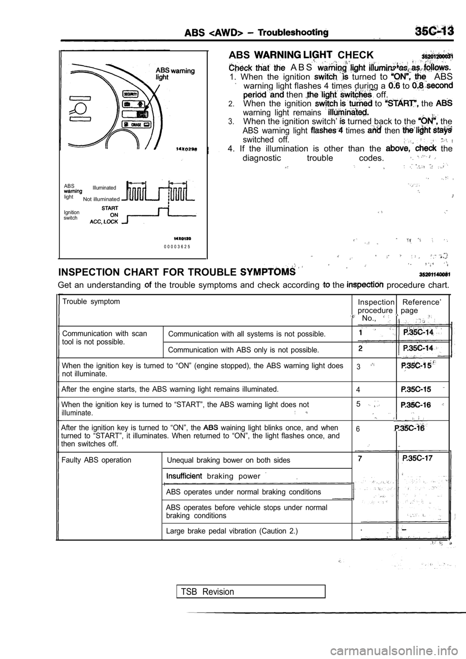
ABS CHECK
A B S
1. When the ignition turned to ABS
warning light flashes 4 times during a to
then off.
2.When the ignition to the
warning light remains
3.When the ignition switch’ turned back to the the
ABS warning light times then
switched off. ,
4. If the illumination is other than the the
diagnostic trouble codes.
ABSIlluminated
light
Not illuminated
Ignition
switch
0 0 0 0 3 6 2 5
INSPECTION CHART FOR TROUBLE
Get an understanding the trouble symptoms and check according the procedure chart.
Trouble symptom
Communication with scan
tool is not possible.Inspection Reference’
procedure
page No.,
Communication with all systems is not possible.
Communication with ABS only is not possible.
When the ignition key is turned to “ON” (engine sto pped), the ABS warning light does
3not illuminate.
After the engine starts, the ABS warning light rema ins illuminated.
4
When the ignition key is turned to “START”, the ABS warning light does not5
illuminate.
After the ignition key is turned to “ON”, the waining light blinks once, and when6turned to “START”, it illuminates. When returned to “ON”, the light flashes once, and
then switches off.
Faulty ABS operation Unequal braking bower on both sides
. braking power
ABS operates under normal braking conditions
ABS operates before vehicle stops under normal braking conditions
Large brake pedal vibration (Caution 2.)
TSB Revision
Page 1744 of 2103
ABS
Caution
1.If movements are made when driving at speed, or when driving on road
with low frictional resistance, or when passing over bumps, the ABS may
sudden braking is not being applied. of this, when getting
2.
check if the problem occurred while driving under s uch conditions
During ABS operation changes in the feeling of the brake pedal occur or
may not be able to be depressed). Such changes are due to in hydraulic
pressure inside the brake line to prevent, the whee ls from locking,
I N S P E C T I O N P R O C E D U R E F O R T R O U B L E S Y M P T O M S ,
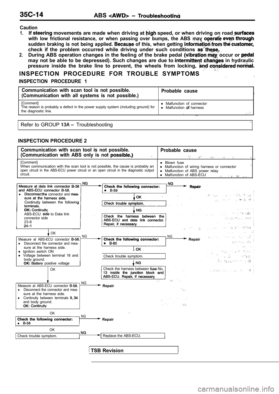
INSPECTION PROCEDURE 1
Communication with scan tool is not possible. Probable cause
(Communication with all systems is not possible.)
[Comment]l Malfunction of connector
The reason is probably a defect in the power supply system (including ground) for
the diagnostic line. l
Malfunction harness
Refer to GROUP Troubleshooting
INSPECTION PROCEDURE 2
Communication with scan tool is not possible.
(Communication with ABS only is not Probable cause
,
[Comment]l Blown fuse
When communication with the scan tool is not possib le, the cause is probably an
l Malfunction of wiring harness or connector
open circuit in the ABS-ECU power circuit or an ope n circuit in the diagnostic output
circuit.l Malfunction of ABS power relay
l Malfunction of ABS-ECU
,
l connector and
Continuity between the following
ABS-ECU
to Data link
connector side
23-8
OKNGMeasure at ABS-ECU connector lDisconnect the connector and mea-sure at the harness side.
N G Repair
l Ignition switch ON
l Voltage between terminal 18 and
bodv around. Check trouble symptom.
I positive voltage
OKCheck the harness between No
NG
Measure at ABS-ECU connector
lDisconnect the connector and mea-sure at the harness side.lContinuity between terminals and body ground.OK:
Repair
l
OKNG Repair
OK
Check trouble symptom. Replace the ABS-ECU.
TSB Revision
Page 1751 of 2103
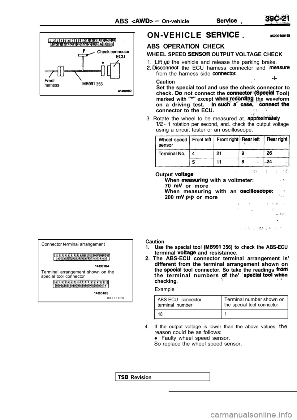
harness 356
ABSOn-vehicle ,
O N - V E H I C L E .
ABS OPERATION CHECK
WHEEL SPEED OUTPUT VOLTAGE CHECK
1. ‘Lift
the vehicle and release the parking brake.
the ECU harness connector and
from the harness side
Caution -I-,.
Set the special tool and use the check connector to
check.
not connect the Tool)
marked with except the waveform
on a driving test.
connector to the ECU.
3. Rotate the wheel to be measured at.
1 rotation per second, and. check the output volta ge
using a circuit tester or an oscilloscope.
Wheel speed Front left
Front right left
Output
When with a voltmeter:
70
or more
When measuring with an
200 or more
. .
.
Connector terminal arrangement
Terminal arrangement shown on the
special tool connector
0 0 0 0 0 0 7 6
Caution
1.Use the special tool 356) to check the ABS-ECU
terminal and resistance.
2. The ABS-ECU connector terminal arrangement is’
different from the terminal arrangement shown on
the tool connector. So take the readings
t h e t e r m i n a l n u m b e r s the’
checking.
Example
ABS-ECU connectorTerminal number shown on
terminal number the special tool connector
181
4.If the output voltage is lower than the above value
s, the
reason could be as follows:
l Faulty wheel speed sensor.
So replace the wheel speed sensor.
Revision
Page 1753 of 2103
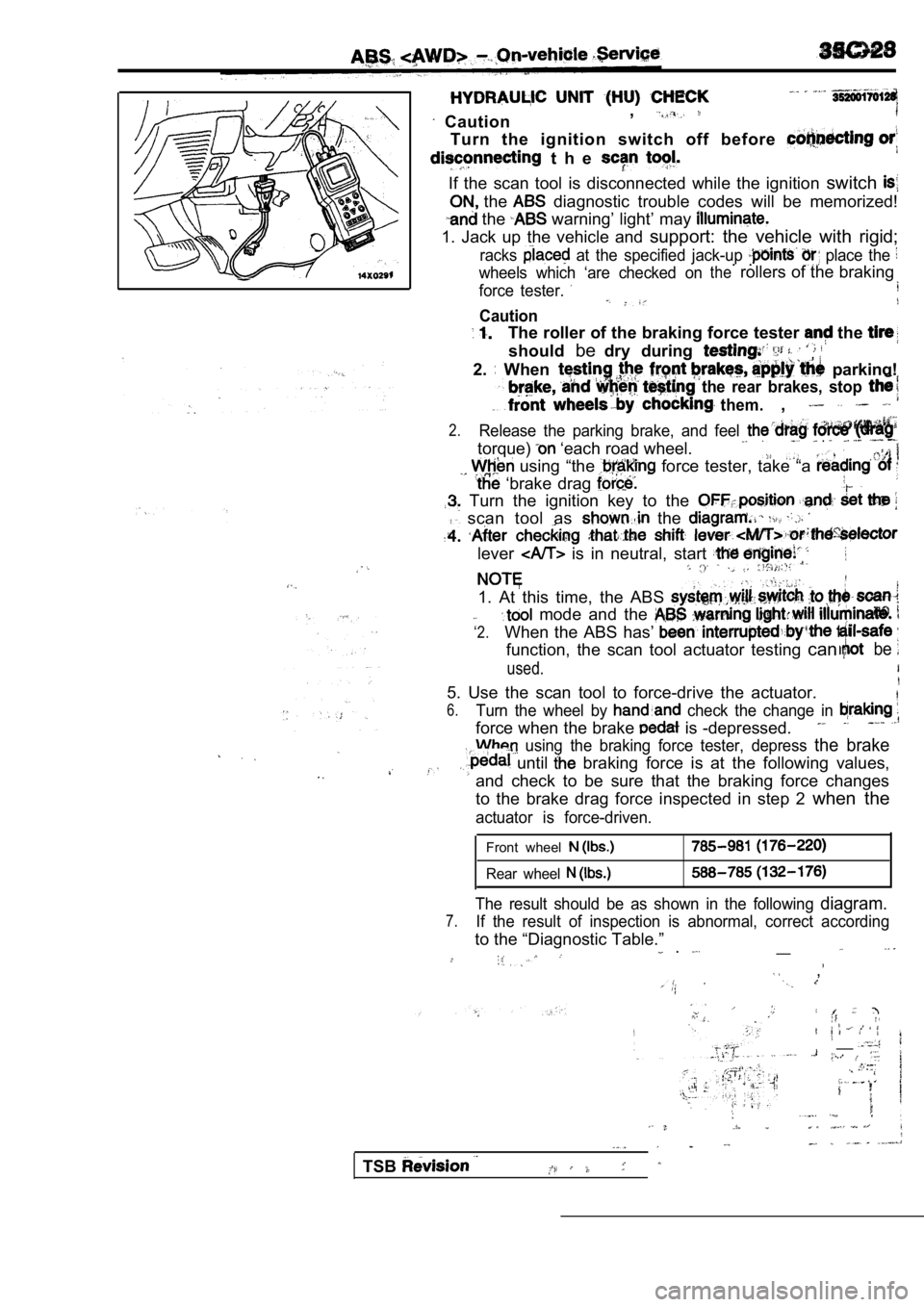
Caution,
Turn the ignition switch off before
t h e
If the scan tool is disconnected while the ignition
switch
the diagnostic trouble codes will be memorized!
the warning’ light’ may
1. Jack up the vehicle and support: the vehicle with rigid;
racks at the specified jack-up place the
wheels which ‘are checked on. .therollers of the braking
force tester.
Caution
The roller of the braking force tester the
shouldbedry during
2. When parking!
the rear brakes, stop
them.,
2.Release the parking brake, and feel
torque) ‘each road wheel. .
using “the force tester, take “a
‘brake drag
Turn the ignition key to the
scan tool as the
lever is in neutral, start
1. At this time, the ABS
‘2.
mode and the
When the ABS has’
function, the scan tool actuator testing canbe
used.
5. Use the scan tool to force-drive the actuator.
6.Turn the wheel by check the change in
force when the brake is -depressed.
using the braking force tester, depress the brake
until braking force is at the following values,
and check to be sure that the braking force changes
to the brake drag force inspected in step 2 when the
actuator is force-driven.
Front wheel
Rear wheel
The result should be as shown in the following diagram.
7.If the result of inspection is abnormal, correct ac cording
to the “Diagnostic Table.”__ .
,
__
TSB
Page 1754 of 2103
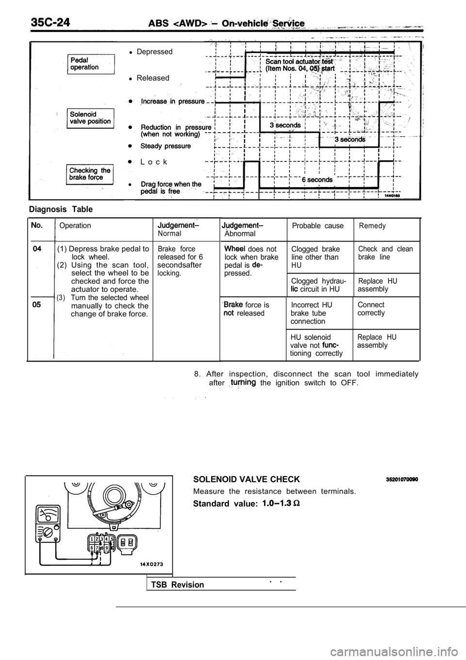
Diagnosis Table
l
l Depressed
l Released
L o c k
Operation
(1) Depress brake pedal to
lock wheel.
(2) Using the scan tool, select the wheel to be
checked and force the
actuator to operate.
(3)Turn the selected wheel
manually to check the
change of brake force.
Normal
Brake force
released for 6
secondsafter
locking.
Abnormal Probable cause
Remedy
does not Clogged brakeCheck and clean
lock when brake line other thanbrake line
pedal is HU
pressed.
Clogged hydrau-
Replace HU
circuit in HUassembly
force is
releasedIncorrect HU
brake tube
connection Connect
correctly
HU solenoid
Replace HU
valve not assembly
tioning correctly
8. After inspection, disconnect the scan tool immed iately
after
the ignition switch to OFF.
SOLENOID VALVE CHECK
Measure the resistance between terminals.
Standard value:
TSB Revision. .
Page 1756 of 2103
ABS On-vehicle Service
ABS-ECU
14
32
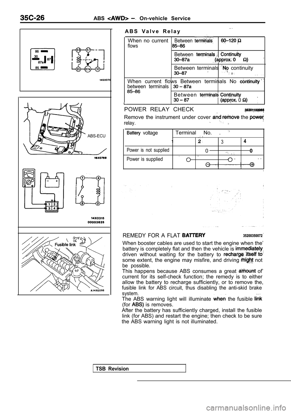
A B S V a l v e R e l a y
When no current
flows
Between
Between
Between terminals continuity
When current flows Between terminals No
between terminals
B e t w e e n
0
POWER RELAY CHECK
Remove the instrument under cover the
relay.
voltageTerminal No. .
34
Power is not supplied00
Power is supplied.
REMEDY FOR A FLAT ,35200350072
When booster cables are used to start the engine wh en the’
battery is completely flat and then the vehicle is
driven without waiting for the battery to
some extent, the engine may misfire, and driving not
be possible.
This happens because ABS consumes a great of’
current for its self-check function; the remedy is to either
allow the battery to recharge sufficiently, or to r emove the,
fusible link for ABS circuit, thus disabling the an ti-skid brake
system.
The ABS warning light will illuminate the fusible
(for is removes.
After the battery has sufficiently charged, install the fusible
link (for ABS) and restart the engine; then check t o be sure
the ABS warning light is not illuminated.
TSB Revision
Page 1763 of 2103
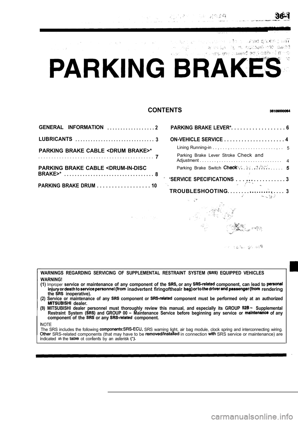
CONTENTS
GENERAL INFORMATION. . . . . . . . . . . . . . . . . . 2PARKING BRAKE LEVER*. . . . . . . . . . . . . . . . . . 6
LUBRICANTS. . . . . . . . . . . . . . . . . . . . . . . . . . . . . . .3ON-VEHICLE SERVICE . . . . . . . . . . . . . . . . . . . . . 4
PARKING BRAKE CABLE
. . . . . . . . , . .5
7Parking Brake Lever Stroke
Check and. . . . . . . . . . . . . . . . . . . . . . . . . . . . . . . . . . . . . . . . . . . .Adjustment . . . . . . . , . . . . . . . . . . . . . . . . . . . . . . . . . .
4
PARKING BRAKE CABLE
BRAKE>*. . . . . . . . . . . . . . . . . . . . . . . . . .
. . . . . . . .8‘SERVICE SPECIFICATIONS . . . . . . . . . . . . . . 3
PARKING BRAKE DRUM . . . . . . . . . . . . . . . . . . 10
TROUBLESHOOTING. . . . . . . . . . . . .
3
WARNINGS REGARDING SERVICING OF SUPPLEMENTAL RESTRA INT SYSTEM EQUIPPED VEHICLES
WARNING!
(1)Improperservice or maintenance of any component of the or any component, can lead to inadvertent firingofthealr renderingthe inoperative).(2) Service or maintenance of any component or component must be performed only at an authorized dealer. MITSUBISHI dealer personnel must thoroughly review this manual, and especially its GROUP Supplemental
Restraint System and GROUP 00 Maintenance Service before beginning any service o r of anycomponent of the or any component.
NOTEThe SRS includes the following SRS warning light, air bag module, clock spring and interconnecting wiring. SRS-related components (that may have to be in connection SRS service or maintenance) are
.. . . indicated the ot contents by an asterisk