brake MITSUBISHI SPYDER 1990 Service Owner's Manual
[x] Cancel search | Manufacturer: MITSUBISHI, Model Year: 1990, Model line: SPYDER, Model: MITSUBISHI SPYDER 1990Pages: 2103, PDF Size: 68.98 MB
Page 495 of 2103
ENGINE
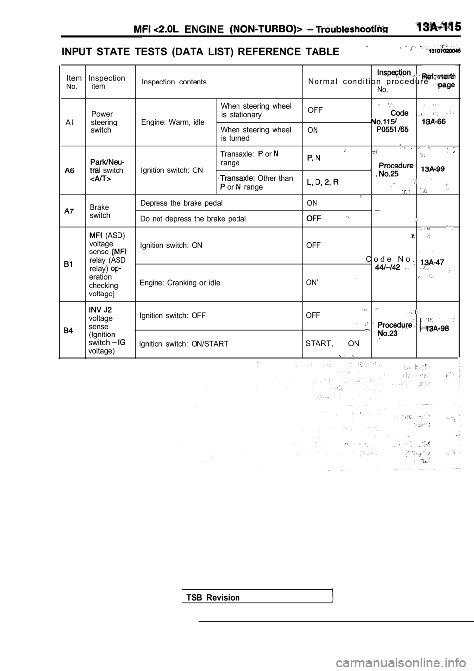
INPUT STATE TESTS (DATA LIST) REFERENCE TABLE
Item Inspection
No.itemInspection contentsN o r m a l c o n d i t i o n p r o c e d u r e
No.
A l
Power
steering
switch
switch
When steering wheel
is stationaryOFF
Engine: Warm, idle
When steering wheelONis turned,
Transaxle: or
rangeIgnition switch: ON
Other than
or range
BrakeDepress the brake pedalON
switch Do not depress the brake pedal.
(ASD)
voltage OFF
senseIgnition switch: ON
relay (ASD
C o d e N o .
relay)
erationON’checking Engine: Cranking or idle
voltage]
voltage Ignition switch: OFF
OFF
sense
(Ignition
switchSTART, ON voltage)Ignition switch: ON/START
TSB Revision
Page 533 of 2103
ENGINE (TURBO)
AND
ENGINE> Troubleshooting
4. Exhaust gas recirculation (EGR) system monitor
Test conditions/procedure
1. All of the following conditions should be satisfied when the drive test is carried out.
(1) Engine coolant temperature:
or higher (when engine is
(2) Outside air temperature: or higher
(3) A/T condition:
lSelector lever position: range
l Overdrive switch: ON
lPower/economy changeover switch: Power
(4) A/C switch:
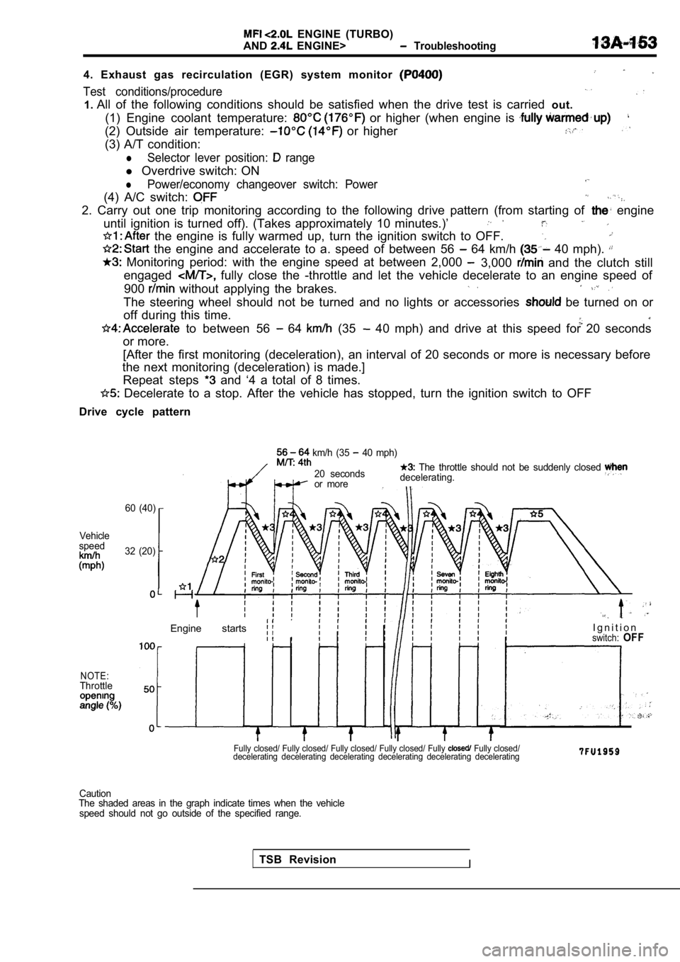
2. Carry out one trip monitoring according to the f ollowing drive pattern (from starting of engine
until ignition is turned off). (Takes approximately 10 minutes.)’
the engine is fully warmed up, turn the ignition s witch to OFF.
the engine and accelerate to a. speed of between 5 6 64 km/h 40 mph).
Monitoring period: with the engine speed at between 2,000 3,000 and the clutch still
engaged
fully close the -throttle and let the vehicle dece lerate to an engine speed of
900
without applying the brakes.
The steering wheel should not be turned and no ligh ts or accessories be turned on or
off during this time.
to between 56 64 (35 40 mph) and drive at this speed for 20 seconds
or more.
[After the first monitoring (deceleration), an inte rval of 20 seconds or more is necessary before
the next monitoring (deceleration) is made.]
Repeat steps
and ‘4 a total of 8 times.
Decelerate to a stop. After the vehicle has stoppe d, turn the ignition switch to OFF
Drive cycle pattern
60 (40)
Vehicle
speed
32 (20)
NOTE:Throttle
km/h (35 40 mph)
20 seconds
The throttle should not be suddenly closed
or more decelerating.
Engine starts I g n i t i o nswitch:OFF
Fully closed/ Fully closed/ Fully closed/ Fully clo
sed/ Fully Fully closed/
decelerating decelerating decelerating decelerating decelerating decelerating
TSB RevisionI
Caution
The shaded areas in the graph indicate times when t he vehicle
speed should not go outside of the specified range.
Page 619 of 2103
ENGINE (TURBO)
AND ENGINE>
Caution
1. Always apply the brakes when shifting the select or lever to ran&, or vehicle will
forward.
2. Driving tests always need another personnel.
NOTE
In a new vehicle [driven approximately 500 km (300 mile) or less], the volume air sensor output
is sometimes 10 higher than the standard frequency.
The injector drive time represents the time when the cranking speed is at 250 or below when the
supply voltage is 11 V.
In a new vehicle [driven approximately 500 km (300 mile) or less], the injector drive time is sometimes
longer than the standard time.
Fuel is injected into all cylinders simultaneously.
In a new vehicle [driven approximately km (300 mile) or less], the step of the stepper mo tor is sometimes
30 steps greater than the standard value.
If the throttle position sensor voltage rises 100 from the voltage when the engine is at idle and th e
closed throttle position switch turns from on to of f at this time, the sensors are normal. If the throttle position
sensor voltage rises 100
from the voltage when the engine is at idle, the t hrottle valve opens, and the
closed throttle position switch turns from on to of f at this, time, the sensors should be adjusted.
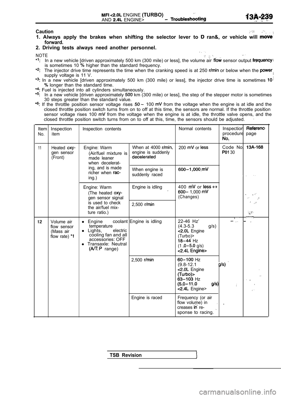
Item Inspection
No.item
Inspection contents Normal contentsInspection
procedure page
11HeatedEngine: WarmWhen at 4000 200 or Code No.
gen sensor engine is suddenly(Air/fuel mixture is 30
(Front)
made leaner
when decelerat- ing, and is made
richer when
When engine is
suddenly raceding.)
Engine: Warm Engine is idling
400 or
(The heated 1,000 ,gen sensor signal(Changes)
is used to check
2,500
the air/fuel mix-
ture ratio.)
Volume airl Engine coolant Engine is idling 22-46 Hz’
flow sensortemperature(4.3-5.3 g/s)
(Mass airl
Lights,electric
flow rate) cooling fan and all Engine
accessories: OFF(Turbo)>
l Transaxle: Neutral Hz
range)(1 g/s)
2,500
Engine is raced
Hz
(9.8-12.1
Engine,
Hz ,
Engine>
Frequency (or air
flow volume) in
creases
re- ,
sponse to racing.
TSB Revision
Page 721 of 2103
INTAKE AND EXHAUST Intake Manifold Engine
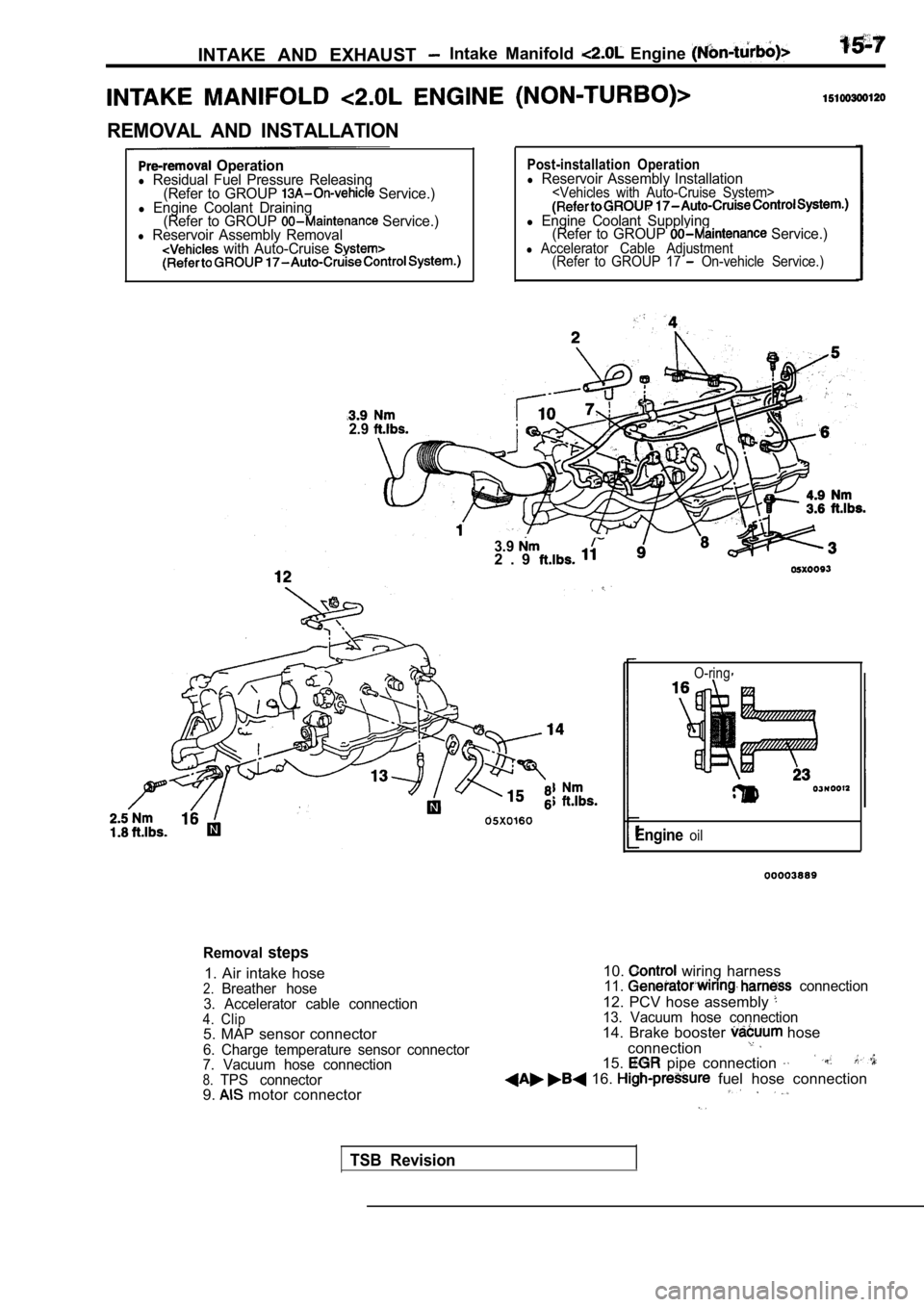
REMOVAL AND INSTALLATION
Operationl Residual Fuel Pressure Releasing(Refer to GROUP Service.)l Engine Coolant Draining(Refer to GROUP Service.)l Reservoir Assembly Removal with Auto-Cruise
2.9
Post-installation Operationl Reservoir Assembly Installation
l Engine Coolant Supplying (Refer to GROUP Service.)l Accelerator Cable Adjustment (Refer to GROUP 17 On-vehicle Service.)
3.92 . 9
O-ring
Engineoil
Removalsteps
1. Air intake hose2.Breather hose
3. Accelerator cable connection
4. Clip5. MAP sensor connector
6. Charge temperature sensor connector
7. Vacuum hose connection
8.TPS connector9. motor connector 10.
wiring harness11. connection
12. PCV hose assembly 13. Vacuum hose connection14. Brake booster hose
connection
15. pipe connection
16. fuel hose connection
TSB Revision
Page 725 of 2103
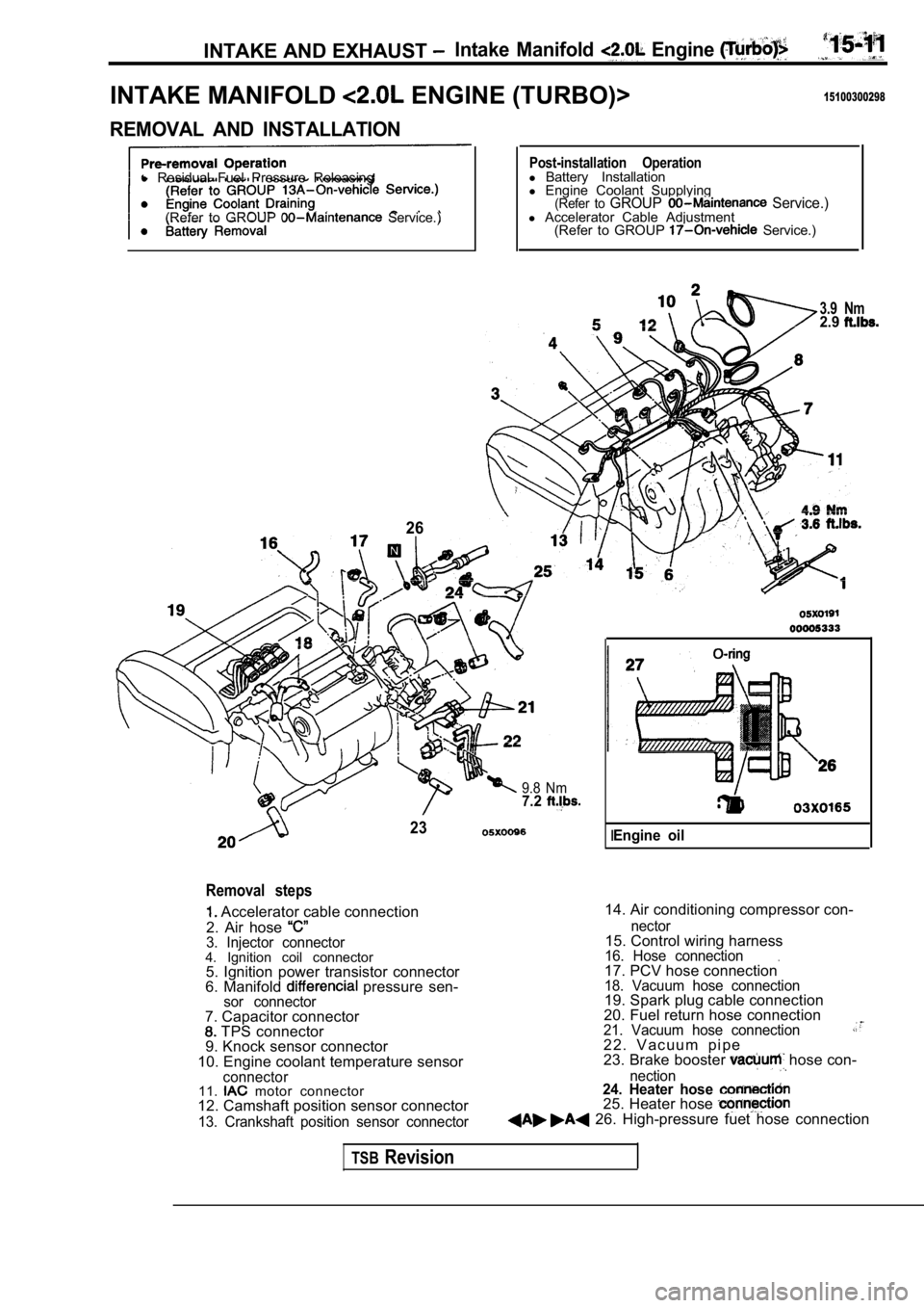
INTAKE AND EXHAUST Intake Manifold Engine
INTAKE MANIFOLD ENGINE (TURBO)>15100300298
REMOVAL AND INSTALLATION
l Residual Fuel Pressure Releasing
(Refer to GROUP
Service.)
26
Post-installation Operationl Battery Installation
l Engine Coolant Supplying
(Refer to GROUP Service.)l Accelerator Cable Adjustment
(Refer to GROUP Service.)
3.9 Nm2.9
9.8 Nm7.2
23
Removal steps
Accelerator cable connection
2. Air hose
3. Injector connector4. Ignition coil connector 5. Ignition power transistor connector
6. Manifold
pressure sen-sor connector
14. Air conditioning compressor con-
7. Capacitor connector
TPS connector
9. Knock sensor connector
10. Engine coolant temperature sensor
connector11. motor connector
12. Camshaft position sensor connector
13. Crankshaft position sensor connector nector
15. Control wiring harness16. Hose connection.17. PCV hose connection18. Vacuum hose connection19. Spark plug cable connection
20. Fuel return hose connection
21. Vacuum hose connection2 2 . V a c u u m p i p e
23. Brake booster hose con-
nection24. Heater hose 25. Heater hose 26. High-pressure fuet hose connection
IEngine oil
TSBRevision
Page 728 of 2103
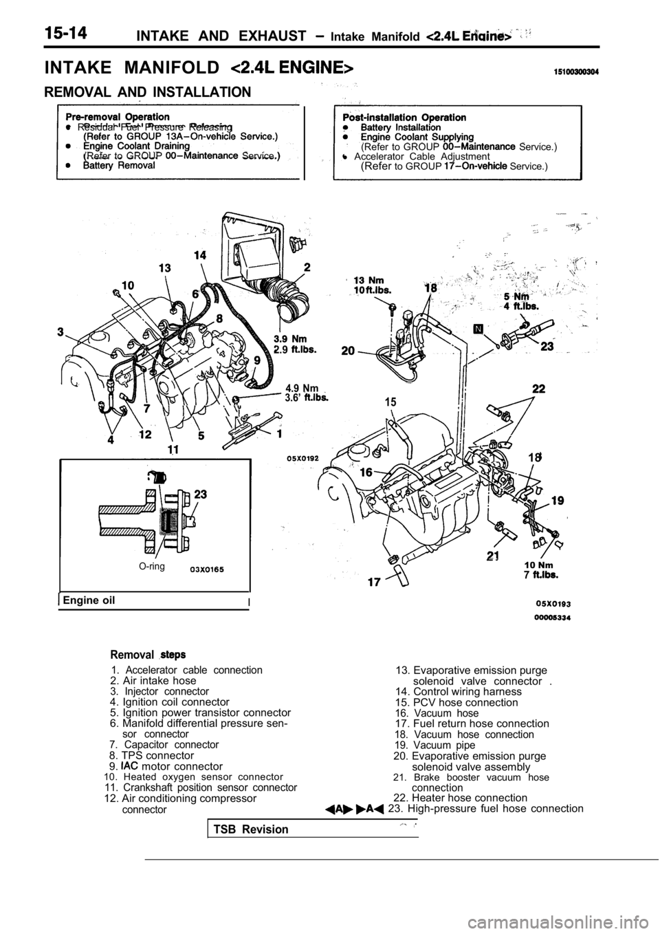
INTAKE AND EXHAUST Intake Manifold
INTAKE MANIFOLD
REMOVAL AND INSTALLATION
l Residual Fuel Pressure Releasing
(Refer to GROUP
Service.) (Refer to GROUP Service.)
l Accelerator Cable Adjustment
(Refer to GROUP
Service.)
2.9
4.9 Nm 3.6’ 15
O-ring
Engine oilI
18
10 Nm7
Removal
1. Accelerator cable connection2. Air intake hose3. Injector connector4. Ignition coil connector
5. Ignition power transistor connector
6. Manifold differential pressure sen-
sor connector
7. Capacitor connector
8. TPS connector
9. motor connector
10. Heated oxygen sensor connector
11. Crankshaft position sensor connector12. Air conditioning compressor
connector
13. Evaporative emission purge
solenoid valve connector .
14. Control wiring harness
15. PCV hose connection
16. Vacuum hose17. Fuel return hose connection18. Vacuum hose connection
19. Vacuum pipe
20. Evaporative emission purge solenoid valve assembly
21. Brake booster vacuum hose
connection22. Heater hose connection 23. High-pressure fuel hose connection
TSB Revision
Page 753 of 2103
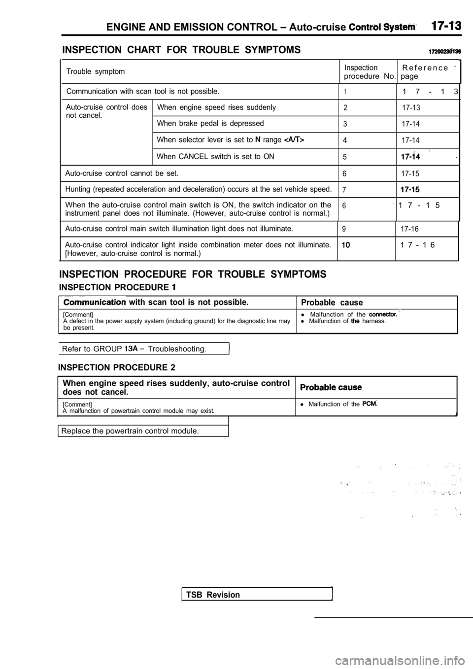
ENGINE AND EMISSION CONTROL Auto-cruise
INSPECTION CHART FOR TROUBLE SYMPTOMS
Trouble symptomInspectionR e f e r e n c e
procedure No. page
Communication with scan tool is not possible.11 7 - 1 3
Auto-cruise control doesWhen engine speed rises suddenly217-13not cancel.
When brake pedal is depressed
3 17-14
When selector lever is set to range 417-14
When CANCEL switch is set to ON5.
Auto-cruise control cannot be set. 617-15
Hunting (repeated acceleration and deceleration) occurs at the set vehicle speed.7
When the auto-cruise control main switch is ON, the switch indicator on the6 1 7 - 1 5instrument panel does not illuminate. (However, aut o-cruise control is normal.)
Auto-cruise control main switch illumination light does not illuminate.
917-16
Auto-cruise control indicator light inside combinat ion meter does not illuminate.1 7 - 1 6
[However, auto-cruise control is normal.)
INSPECTION PROCEDURE FOR TROUBLE SYMPTOMS
INSPECTION PROCEDURE
with scan tool is not possible.
Probable cause
[Comment] l
Malfunction of the A defect in the power supply system (including grou nd) for the diagnostic line mayl Malfunction of harness.
be present.
Refer to GROUP
Troubleshooting.
INSPECTION PROCEDURE 2 When engine speed rises suddenly, auto-cruise contr ol
does not cancel.
[Comment]A malfunction of powertrain control module may exist.
Replace the powertrain control module. l
Malfunction of the
TSB Revision
Page 754 of 2103
![MITSUBISHI SPYDER 1990 Service Owners Manual ENGINE AND EMISSION CONTROL Auto-cruise Control System
INSPECTION PROCEDURE 3
When brake pedal is depressed,, auto-cruise control does not
cancel.
[Comment]A malfunction of the stop li](/img/19/57345/w960_57345-753.png "MITSUBISHI SPYDER 1990 Service Owners Manual ENGINE AND EMISSION CONTROL Auto-cruise Control System
INSPECTION PROCEDURE 3
When brake pedal is depressed,, auto-cruise control does not
cancel.
[Comment]A malfunction of the stop li")
ENGINE AND EMISSION CONTROL Auto-cruise Control System
INSPECTION PROCEDURE 3
When brake pedal is depressed,, auto-cruise control does not
cancel.
[Comment]A malfunction of the stop light switch or stop ligh t circuit may exist.
Probable cause
l Malfunction of the stop light switch.
l Malfunction of the connector.
l Malfunction of the
l Malfunction of the PCM.
Stop light switch check.
(Refer to
OK
Measure at stop
switch connector
lDisconnect the connector and mea-sure at the harness side.
l Voltage between terminal (1) and
ground positive voltage
following connectors:
NG
63 and
NG
Check troubleNGsymp Check the l i g h t a n d P C M . R e p a i r ,
OK Check trouble symptom.
Replace the PCM.
light switch and the
ground.
,
INSPECTION PROCEDURE 4
When selector lever is set to range, auto-cruise control does
not cancel.
[Comment]An open-circuit in the output signal circuit in IN range may be present.
OK
and.
TSB Revision
Inspect thebetween the NG
transaxle range switch and PCM.
OK
the PCM.
INSPECTION PROCEDURE 5
When auto-cruise control CANCEL switch is set to ON ,
auto-cruise control does not cancel. Probable cause
[Comment]An open-circuit inside the CANCEL switch may be pre
sent.l
Malfunction of the auto-cruise control switch.
Replace the auto-cruise control
Page 759 of 2103
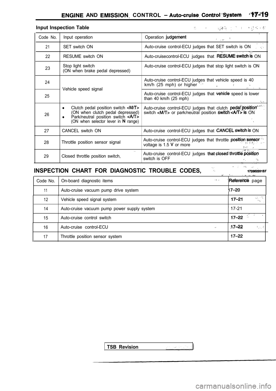
AND CONTROL
Input Inspection Table
.
Code No.Input operation Operation
21SET switch ONAuto-cruise control-ECU judges that SET switch is O
N
22RESUME switch ON Auto-cruisecontrol-ECU judges that ON
23 Stop light switch
(ON when brake pedal depressed) Auto-cruise control-ECU judges that stop light swit
ch is ON
24
25
26Auto-cruise control-ECU judges that vehicle speed i s 40
km/h (25 mph) or higher ,Vehicle speed signal
Auto-cruise control-ECU judges that speed is lower
than 40 km/h (25 mph)
lClutch pedal position switch Auto-cruise control-ECU judges that clutch (ON when clutch pedal depressed) Park/neutral position switch switch or park/neutral position ONl(ON when selector lever in range)
27 CANCEL switch ON Auto-cruise control-ECU judges that
ON
28 Throttle position sensor signal Auto-cruise control-ECU judges that throttle
voltage is 1.5 or more
29Closed throttle position switch,Auto-cruise control-ECU judges
switch is OFF
INSPECTION CHART FOR DIAGNOSTIC TROUBLE CODES,
Code No.
On-board diagnostic items page
11Auto-cruise vacuum pump drive system
12
14
15
Vehicle speed signal system
Auto-cruise vacuum pump power supply system
Auto-cruise control switch
17-21
.
16
17
Auto-cruise control-ECU
Throttle position sensor system
TSB Revision
Page 763 of 2103
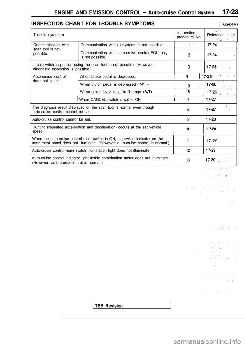
ENGINE AND EMISSION CONTROL Auto-cruise Control
INSPECTION CHART FOR SYMPTOMS
Communication with
scan tool is not
possible. Communication with systems is not possible.
Communication with auto-cruise control-ECU only
is not possible.1
2
Input switch inspection using the scan tool is not possible. (However,
diagnostic inspection is possible.)3 .
Auto-cruise control When brake pedal is depressed 4 does not cancel. When clutch pedal is depressed
When select lever is set to range
When CANCEL switch is set to ON
5
17-26
I 7 17-27
Trouble symptomInspection
procedure No.Reference page
The diagnosis result displayed on the scan tool is normal even though
auto-cruise control cannot be set.
Auto-cruise control cannot be set.I9
Hunting (repeated acceleration and deceleration) oc curs at the set vehicle
speed.I1
When the auto-cruise control main switch is ON, the switch indicator on the
instrument panel does not illuminate. (However, aut o-cruise control is normal.)
Auto-cruise control main switch illumination light does not illuminate.111 7 - 2 9 , .
1217-29
Auto-cruise control indicator light inside combinat ion meter does not illuminate.
(However, auto-cruise control is normal.)13
TSB Revision