fuel pressure MITSUBISHI SPYDER 1990 Service Repair Manual
[x] Cancel search | Manufacturer: MITSUBISHI, Model Year: 1990, Model line: SPYDER, Model: MITSUBISHI SPYDER 1990Pages: 2103, PDF Size: 68.98 MB
Page 41 of 2103
GENERAL Maintenance Service
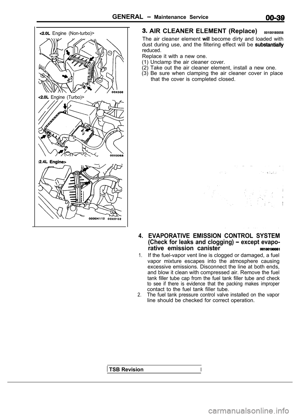
Engine (Non-turbo)>
Engine (Turbo)>
AIR CLEANER ELEMENT (Replace)00100180058
The air cleaner element become dirty and loaded with
dust during use, and the filtering effect will be
reduced.
Replace it with a new one.
(1) Unclamp the air cleaner cover.
(2) Take out the air cleaner element, install a new one.
(3) Be sure when clamping the air cleaner cover in place
that the cover is completed closed.
4.EVAPORATIVE EMISSION CONTROL SYSTEM
(Check for leaks and clogging)
except evapo-
rative emission canister
1.If the fuel-vapor vent line is clogged or damaged, a fuel
vapor mixture escapes into the atmosphere causing
excessive emissions. Disconnect the line at both en ds,
and blow it clean with compressed air. Remove the f uel
tank filler tube cap from the fuel tank filler tube and check
to see if there is evidence that the packing makes improper
contact to the fuel tank filler tube.
2.The fuel tank pressure control valve installed on the vapor
line should be checked for correct operation.
TSB RevisionI
Page 57 of 2103
GENERAL Main and Adhesive Table
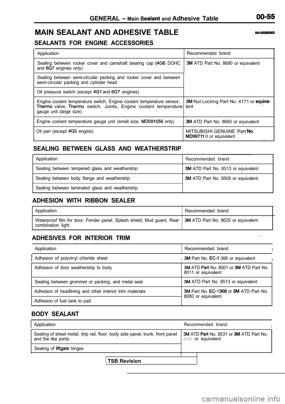
MAIN SEALANT AND ADHESIVE TABLE
SEALANTS FOR ENGINE ACCESSORIES
Application Recommended brand
Sealing between rocker cover and camshaft bearing c ap
DOHC ATD Part No. 8680 or equivalent
and
engines only)
1Sealing between semi-circular packing and rocker co ver and between
semi-circular packing and cylinder head
Oil pressure switch (except
and engines). . .
Engine coolant temperature switch, Engine coolant t emperature sensor, Nut Locking Part No. 4171 or
valve, switch, Joints, Engine coolant temperature lent
gauge unit (large size)
Engine coolant temperature gauge unit (small size, only) ATD Part No. 8660 or equivalent
Oil pan (except
engine)MITSUBISHI GENUINE ‘Part
0 or equivalent
SEALING BETWEEN GLASS AND WEATHERSTRIP
Application
Sealing between tempered glass and weatherstrip
Sealing between body flange and weatherstrip
Sealing between laminated glass and weatherstripRecommended brand
ATD Part No. 8513 or equivalent
ATD Part No. 8509 or equivalent
ADHESION WITH RIBBON SEALER
Application Recommended brand
Waterproof film for door, Fender panel, Splash shie ld, Mud guard, Rear
ATD Part No. 8625 or equivalent
combination light
ADHESIVES FOR INTERIOR TRIM
Application Recommended brandI
Adhesion of polyvinyl chloride sheetI Part No. 368 or equivalentI
Adhesion of door weatherstrip to body ATD No. 8001 or ATD Part No.
8011 or equivalent
Sealing between grommet or packing, and metal seal
Adhesion of headlining and other interior trim mate rials
Adhesion of fuel tank to pad
ATD Part No. 8513 or equivalent
Part No. or ATD Part No.
8080 or equivalent
BODY SEALANT
ApplicationRecommended brandI
Sealing of sheet metal, drip rail, floor, body side panel, trunk, front panel ATD No. 8531 or ATD Part No.
and the like joints8848or equivalent
Sealing of
hinges
TSB Revision
Page 71 of 2103
ENGINE On-vehicle
8. If the standard value is exceeded, check the following
items:
l Diagnostic output
l Closed-loop control (When the closed-loop control
is carried out normally, the output signal of the h eated
oxygen sensor repeats between and
,000 at idle.)
l Fuel pressure
I n j e c t o r
lIgnition coil, spark plug cable, spark plug
lEGR system and the EGR valve leak
l Evaporative emission control system
Compression pressure
NOTE
Replace the catalyst whenever the
HC contents do not remain inside the standard value .
(even though the result of the inspection is
all items.).
C O M P R E S S I O N
CHECK
1.Before inspection, check that the engine-oil, start er
battery are normal. Also, set the to the
condition:
lEngine coolant temperature:
lLights, electric cooling fan and all accessories: O FF
lTransaxle: Neutral (P range on vehicles with
2. Disconnect the spark plug cables.
3. Remove all of the spark plugs.
4.
5.
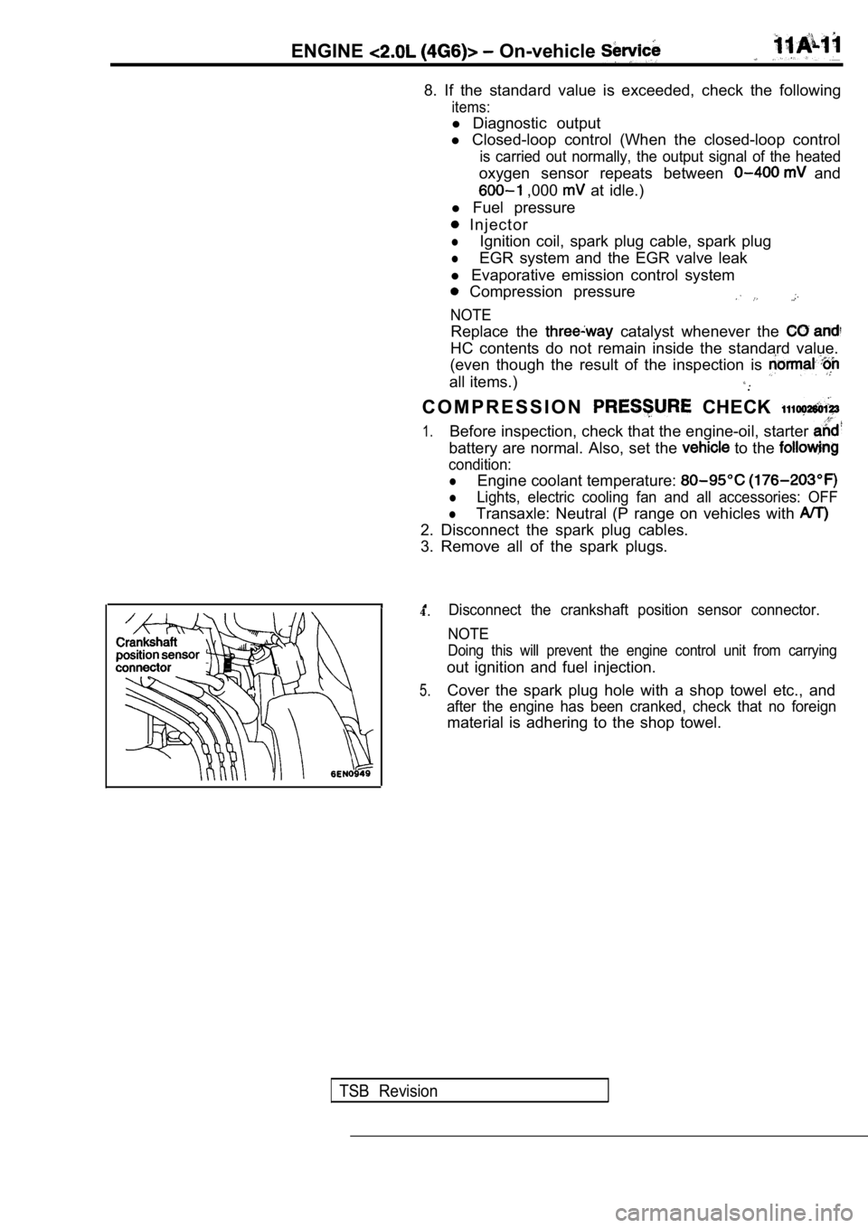
Disconnect the crankshaft position sensor connector .
NOTE
Doing this will prevent the engine control unit fro m carrying
out ignition and fuel injection.
Cover the spark plug hole with a shop towel etc., a nd
after the engine has been cranked, check that no fo reign
material is adhering to the shop towel.
TSB Revision
Page 72 of 2103
ENGINE On-vehicle
Caution
1.Keep away from the spark plug hole when crank-
ing.
2. If compression is measured with water, oil, fuel,
etc., that has come from cracks inside the cylinder ,
these materials will become heated and will gush
out from the spark plug hole, which is dangerous.
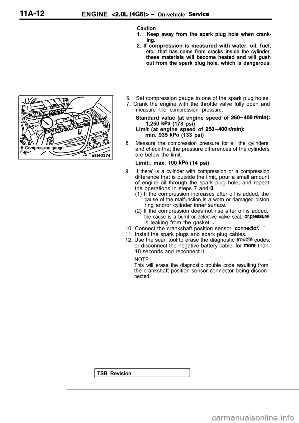
6.Set compression gauge to one of the spark plug hole s.
7. Crank the engine with the throttle valve fully o pen and
measure the compression pressure.
Standard value (at engine speed of
1,250 (178 psi)
Limit (at engine speed of
min. 935 (133 psi)
8.Measure the compression pressure for all the cylind ers,
and check that the pressure differences of the cylinders
are below the limit.
Limit:. max. 100
(14 psi)
9.If there’ is a cylinder with compression or a compr ession
difference that is outside the limit, pour a small amount
of engine oil through the spark plug hole, and repe at
the operations in steps 7 and
(1) If the compression increases after oil is added , the
cause of the malfunction is a worn or damaged pisto n
ring and/or cylinder inner
(2) If the compression does not rise after oil is added,
the cause is a burnt or defective valve seat,
is leaking from the gasket.
10. Connect the crankshaft position sensor
11. Install the spark plugs and spark plug cables.
12. Use the scan tool to erase the diagnostic
codes,
or disconnect the negative battery cable’ for
than
10 seconds and reconnect it.
NOTE
This will erase the diagnostic trouble code from
the crankshaft position sensor connector being disc on-
nected.
TSB Revision
Page 73 of 2103
ENGINE On-vehicle Service
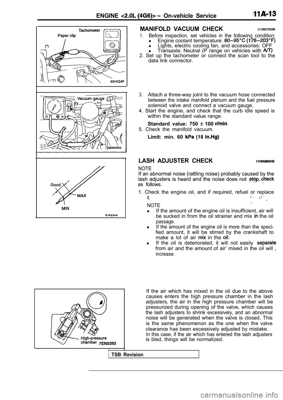
MANIFOLD VACUUM CHECK11100270200
1.Before inspection, set vehicles in the following condition:
lEngine coolant temperature:
lLights, electric cooling fan, and accessories: OFF
l Transaxle: Neutral (P range on vehicles with
2. Set up the tachometer or connect the scan tool t o the
data link connector.
3.Attach a three-way joint to the vacuum hose connect ed
between the intake manifold plenum and the fuel pressure
solenoid valve and connect a vacuum gauge.
4. Start the engine, and check that the curb idle s peed is
within the standard value range.
Standard value: 750
100
5. Check the manifold vacuum.
Limit: min. 60
(18
LASH ADJUSTER CHECK
NOTE
NOTE
If an abnormal noise (rattling noise) probably caus ed by the
If an abnormal noise (rattling noise) probably caus ed by the
lash adjusters is heard and the noise does not
lash adjusters is heard and the noise does not
as follows.
as follows.
1. Check the engine oil, and if required, refuel or replace
it.
NOTE
lIf the amount of the engine oil is insufficient, ai r will
be sucked in from the oil strainer and mix
the oil
passage.
lIf the amount of the engine oil is more than the sp eci-
fied amount, it will be stirred by the crankshaft to
make a lot of air
in the
l If the oil is deteriorated, it will not easily
from air and the amount of air’ mixed in the oil wi ll ,
increase.
If the air which has mixed in the oil due to the ab ove
causes enters the high pressure chamber in the lash
adjusters, the air in the high pressure chamber wil l be
pressurized during opening of the valve, which caus es
the lash adjusters to shrink excessively, and an abnormal
noise will be generated when the valve is closed. T his
is the same phenomenon as the one when the valve
clearance has been excessively adjusted by mistake.
In this case, if the air which has entered the lash adjusters
is bled, things will be normalized.
TSB Revision
Page 76 of 2103
ENGINE Engine
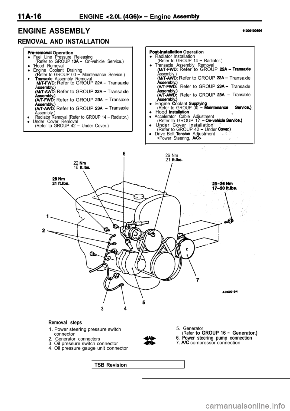
ENGINE ASSEMBLY
REMOVAL AND INSTALLATION
Operationl Fuel Line Pressure Releasing(Refer to GROUP On-vehicle Service.)l ‘Hood Removall Engine Coolant DrainingRefer to GROUP 00 Maintenance Service.)l Assembly Removal Refer to GROUP TransaxleA Refer to GROUP Transaxle
Refer to GROUP Transaxle
Refer to GROUP TransaxleAssembly.)lRadiator Removal (Refer to GROUP 14 Radiator.)l Under Cover Removal (Refer to GROUP 42 Under Cover.)
6
2216
Operationl Radiator Installation(Refer to GROUP 14 Radiator.)l Transaxle Assembly Removal Refer to GROUP Assembly.) Refer to GROUP Transaxle
Refer to GROUP Transaxle
Refer to GROUP
Transaxle
l Engineoolant(Refer to GROUP 00 l Hoodl Accelerator Cable Adjustment(Refer to GROUP 17 l Under Cover Installation(Refer to GROUP 42 Under l Drive Belt Adjustment
34
Removal steps
1. Power steering pressure switchconnector
2. Generator connectors
3. Oil pressure switch connector
4. Oil pressure gauge unit connector
5. Generator(Referto GROUP 16 Generator.)
6. Power steering pump connection7. compressor connection
TSB Revision
Page 77 of 2103
ENGINE Engine Assembly
4.9
29
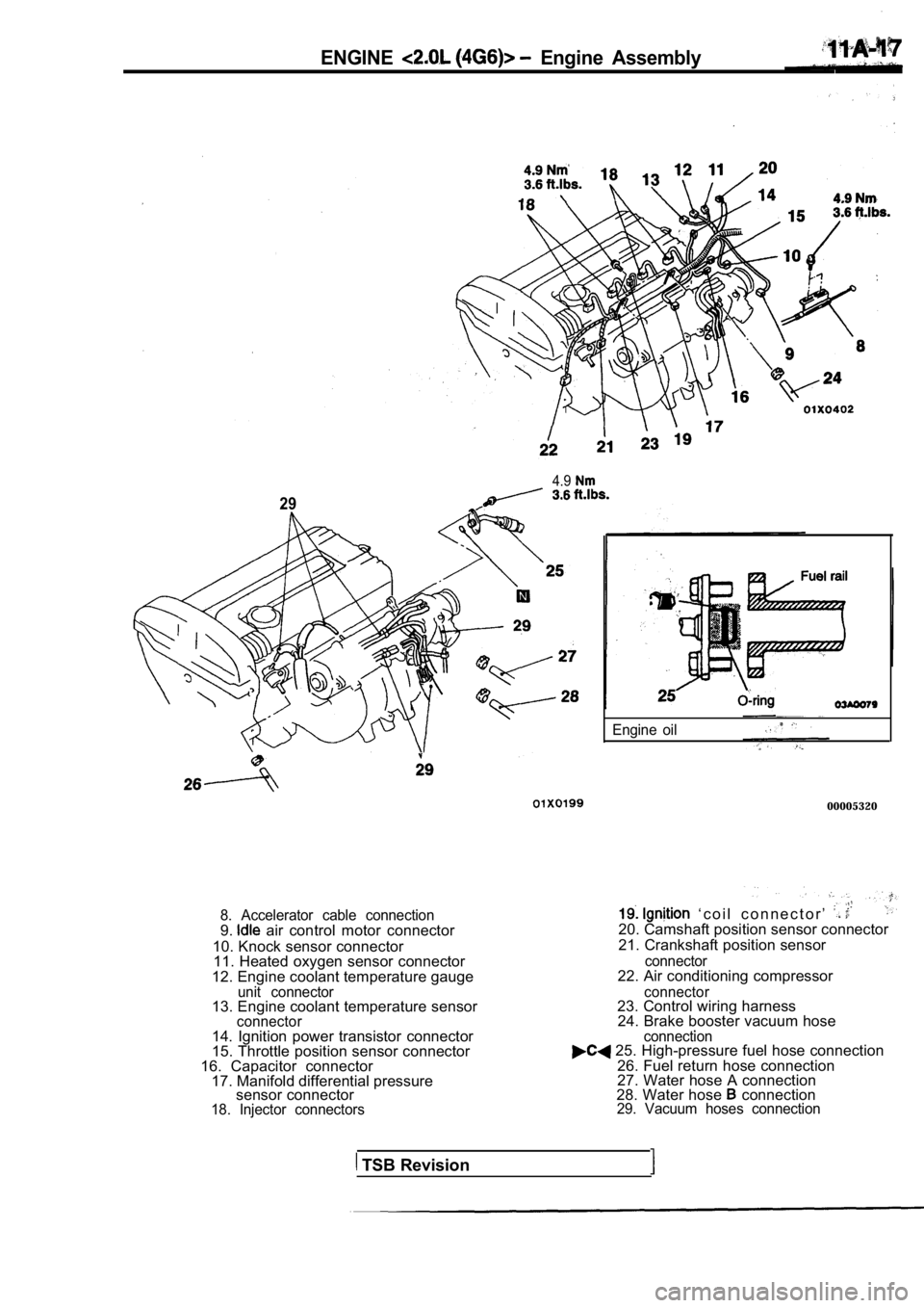
8. Accelerator cable connection9. air control motor connector
10. Knock sensor connector 11. Heated oxygen sensor connector
12. Engine coolant temperature gauge
unit connector13. Engine coolant temperature sensorconnector
Engine oil
00005320
‘ c o i l c o n n e c t o r ’ 20. Camshaft position sensor connector
21. Crankshaft position sensor
connector22. Air conditioning compressor
connector23. Control wiring harness 24. Brake booster vacuum hose .
14. Ignition power transistor connector
15. Throttle position sensor connector
16. Capacitor connector 17. Manifold differential pressure sensor connector
18. Injector connectors connection
25. High-pressure fuel hose connection
26. Fuel return hose connection
27. Water hose A connection
28. Water hose
connection29. Vacuum hoses connection
TSB Revision
Page 80 of 2103
ENGINE Engine ,
Engine side
Arrow
topper
bracket
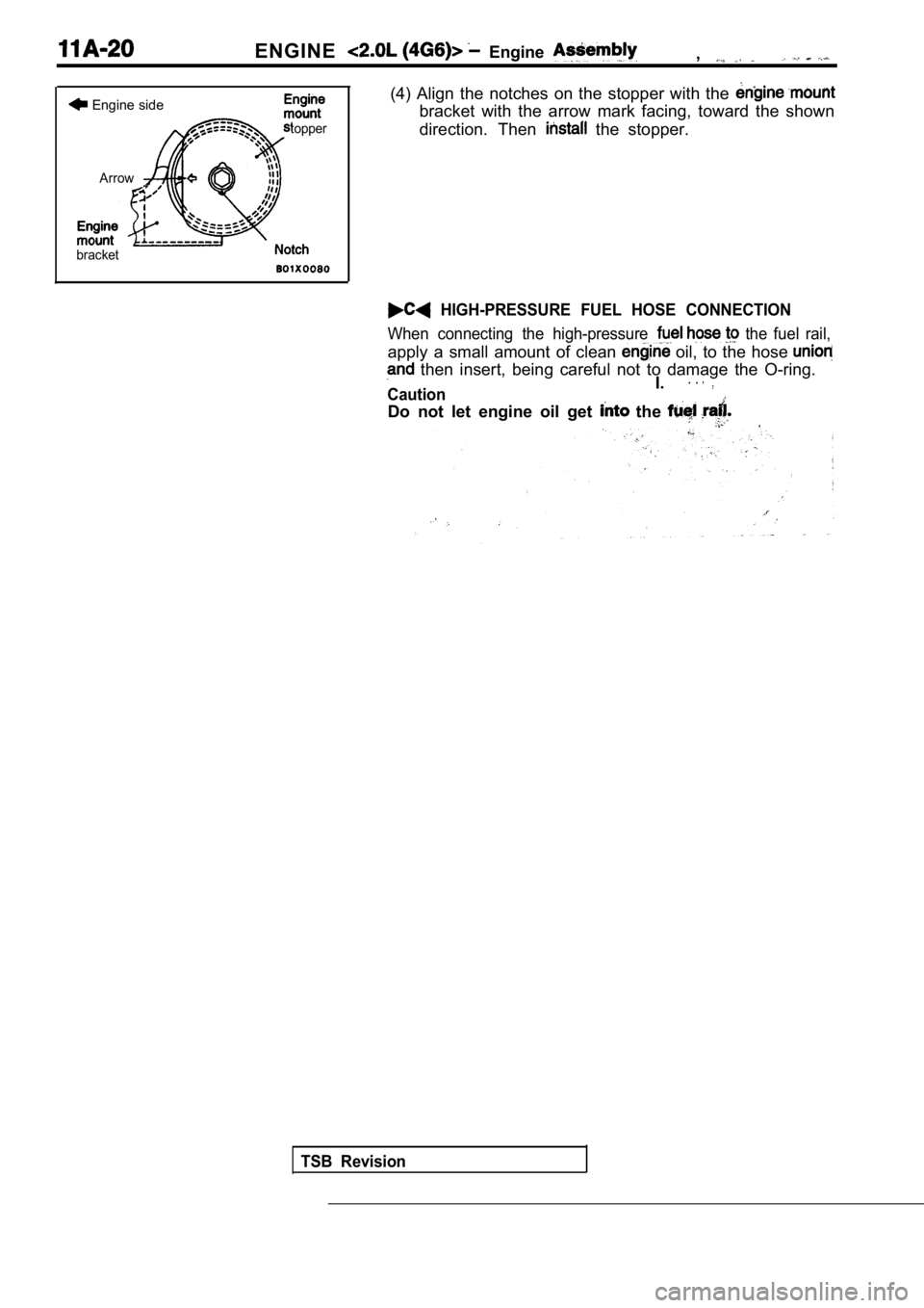
(4) Align the notches on the stopper with the
bracket with the arrow mark facing, toward the show n
direction. Then
the stopper.
HIGH-PRESSURE FUEL HOSE CONNECTION
When connecting the high-pressure the fuel rail,
apply a small amount of clean oil, to the hose
then insert, being careful not to damage the O-rin g.. .
CautionI.
Do not let engine oil get the .
TSB Revision
Page 91 of 2103
ENGINE Cylinder Head
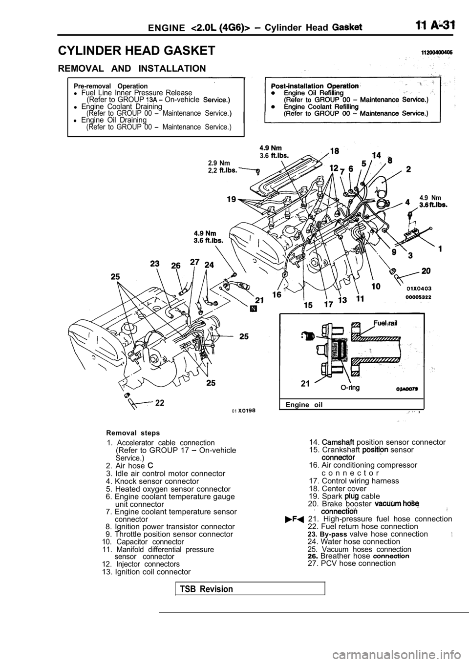
CYLINDER HEAD GASKET
REMOVAL AND INSTALLATION
Pre-removal Operationl Fuel Line Inner Pressure Release(Refer to GROUP On-vehiclel Engine Coolant Draining(Refer to GROUP 00 Maintenance Service.)l Engine Oil Draining(Refer to GROUP 00 Maintenance Service.)
3.62.9 Nm
2.2
4.9 Nm
220 1
Removal steps
1. Accelerator cable connection(Refer to GROUP 17 On-vehicleService.)2. Air hose 3. Idle air control motor connector
4. Knock sensor connector
5. Heated oxygen sensor connector
6. Engine coolant temperature gauge
unit connector
7. Engine coolant temperature sensor
connector8. Ignition power transistor connector
9. Throttle position sensor connector
10. Capacitor connector
11. Manifold differential pressure sensor connector
12. Injector connectors
13. Ignition coil connector Engine oil
,
21
14. position sensor connector
15. Crankshaft sensor
16. Air conditioning compressor
c o n n e c t o r
17. Control wiring harness
18. Center cover
19. Spark
cable
20. Brake booster
21. High-pressure fuel hose connection 22. Fuel return hose connection
23. By-pass valve hose connection
24. Water hose connection25. Vacuum hoses connection26.Breather hose 27. PCV hose connection
TSB Revision
Page 95 of 2103
ENGINE Cylinder Head Gasket
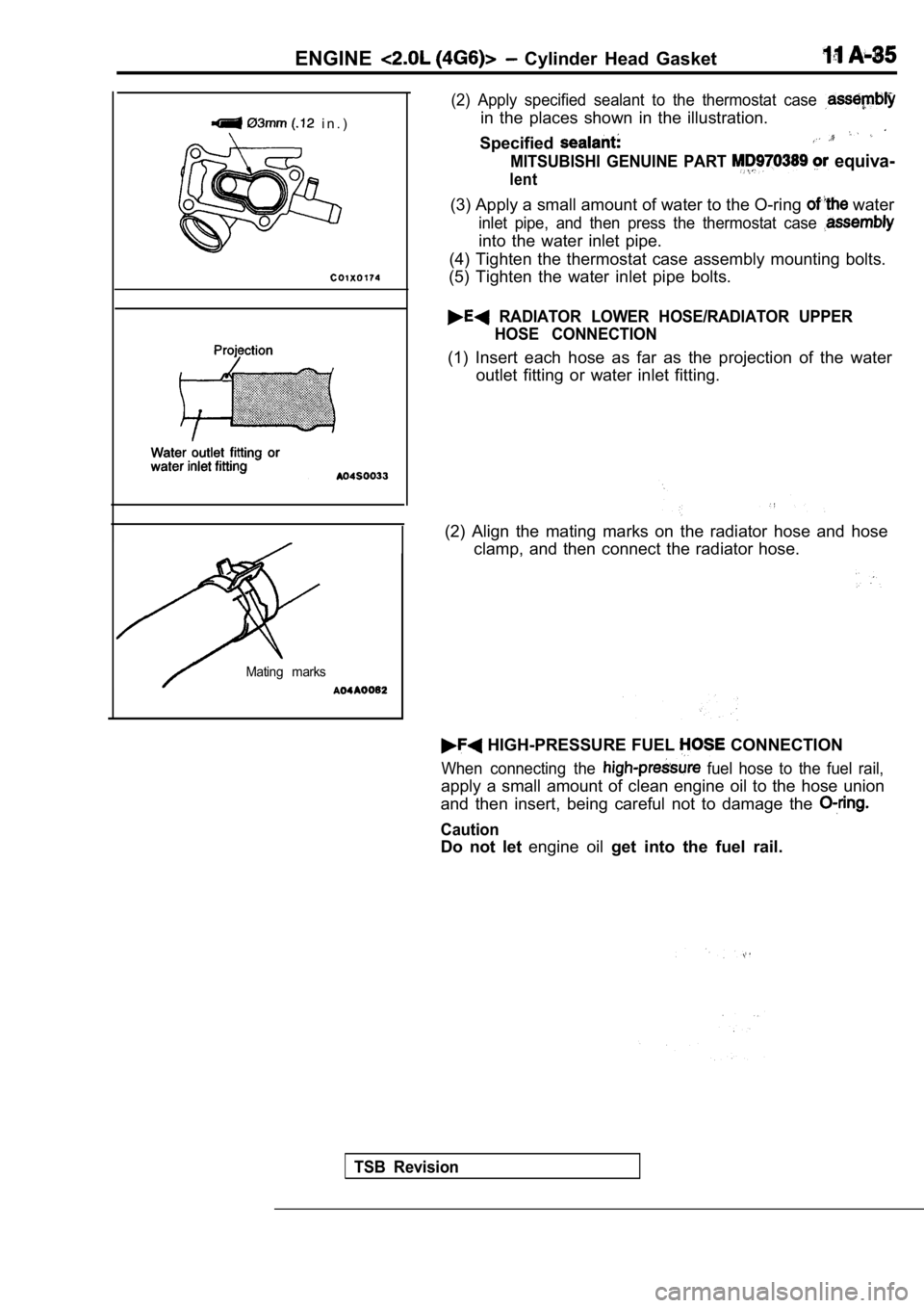
i n . )
Mating marks
(2) Apply specified sealant to the thermostat case
in the places shown in the illustration.
Specified
MITSUBISHI GENUINE PART equiva-
lent
(3) Apply a small amount of water to the O-ring water
inlet pipe, and then press the thermostat case
into the water inlet pipe.
(4) Tighten the thermostat case assembly mounting b olts.
(5) Tighten the water inlet pipe bolts.
RADIATOR LOWER HOSE/RADIATOR UPPER HOSE CONNECTION
(1) Insert each hose as far as the projection of th e water
outlet fitting or water inlet fitting.
(2) Align the mating marks on the radiator hose and hose
clamp, and then connect the radiator hose.
HIGH-PRESSURE FUEL CONNECTION
When connecting the fuel hose to the fuel rail,
apply a small amount of clean engine oil to the hos e union
and then insert, being careful not to damage the
Caution
Do not let engine oil get into the fuel rail.
TSB Revision