key MITSUBISHI SPYDER 1990 Service Repair Manual
[x] Cancel search | Manufacturer: MITSUBISHI, Model Year: 1990, Model line: SPYDER, Model: MITSUBISHI SPYDER 1990Pages: 2103, PDF Size: 68.98 MB
Page 25 of 2103
GENERAL Towing and Hoisting
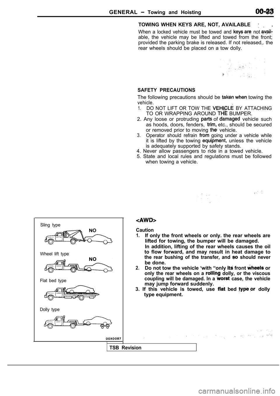
Sling type
Wheel lift type
Flat bed type
Dolly type
TOWING WHEN KEYS ARE, NOT, AVAILABLE .
When a locked vehicle must be towed and not
able, the vehicle may be lifted and towed from the front;
provided the parking brake is released. If not rele ased,. the
rear wheels should be placed on a tow dolly.
SAFETY PRECAUTIONS
The following precautions should be towing the
vehicle.
1.DO NOT LIFT OR TOW THE BY ATTACHING
TO OR WRAPPING AROUND BUMPER.
2. Any loose or protruding
of vehicle such
as hoods, doors, fenders,
etc., should be secured
or removed prior to moving
vehicle.
3.Operator should refrain going under a vehicle while
it is lifted by the towing unless the vehicle
is adequately supported by safety stands.
4. Never allow passengers to ride in a towed vehicl e.
5. State and local rules and regulations must be fo llowed
when towing a vehicle.
Caution
1.If only the front wheels or only. the rear wheels a re
lifted for towing, the bumper will be damaged.
In addition, lifting of the rear wheels causes the oil
to flow forward, and may result in heat damage to
the rear bushing of the transfer, and should never
be done.
2.Do not tow the vehicle ‘with “only front or
only the rear wheels on a dolly, or the viscous
coupling will be damaged. In a
case, the vehicle
may jump forward suddenly.
3. If this vehicle is towed, use
bed dolly
type equipment.
TSB Revision
Page 53 of 2103
GENERAL Maintenance
21 SYSTEM component
damage, to wiring,
harness, etc.)
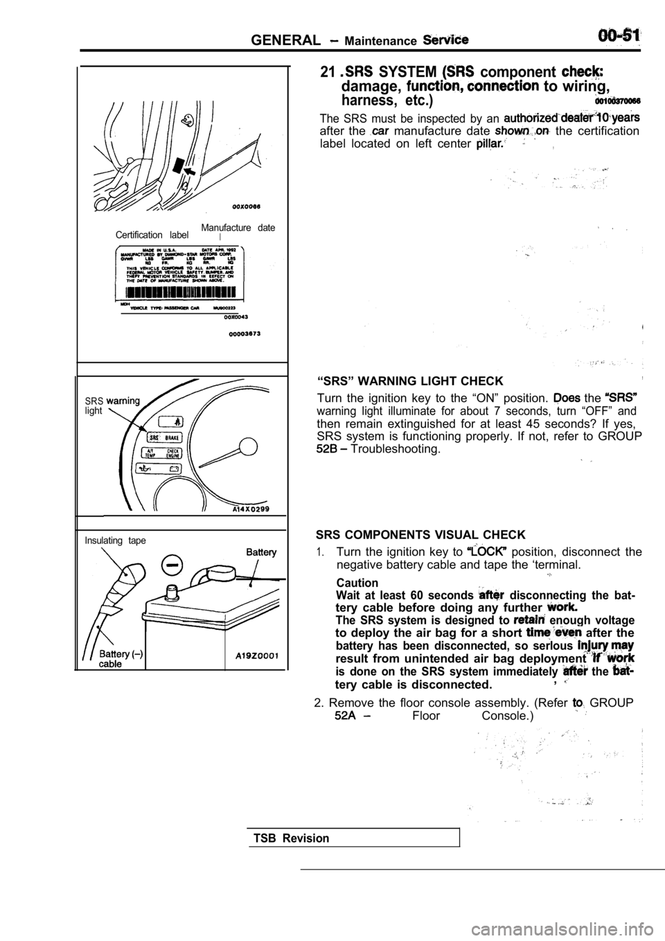
Certification labelManufacture dateI
SRSlight
Insulating tape
The SRS must be inspected by an
after the manufacture date the certification
label located on left center
,
“SRS” WARNING LIGHT CHECK,
Turn the ignition key to the “ON” position. the
warning light illuminate for about 7 seconds, turn “OFF” and
then remain extinguished for at least 45 seconds? I f yes,
SRS system is functioning properly. If not, refer t o GROUP
Troubleshooting.
SRS COMPONENTS VISUAL CHECK
1.Turn the ignition key to position, disconnect the
negative battery cable and tape the ‘terminal.
Caution
Wait at least 60 seconds
disconnecting the bat-
tery cable before doing any further
The SRS system is designed to enough voltage
to deploy the air bag for a short after the
battery has been disconnected, so serlous
result from unintended air bag deployment
is done on the SRS system immediately the
tery cable is disconnected. ,
2. Remove the floor console assembly. (Refer GROUP
Floor Console.)
TSB Revision
Page 69 of 2103
ENGINE On-vehicle
A/C COMPRESSOR DRIVE BELT TENSION ADJUSTMENT
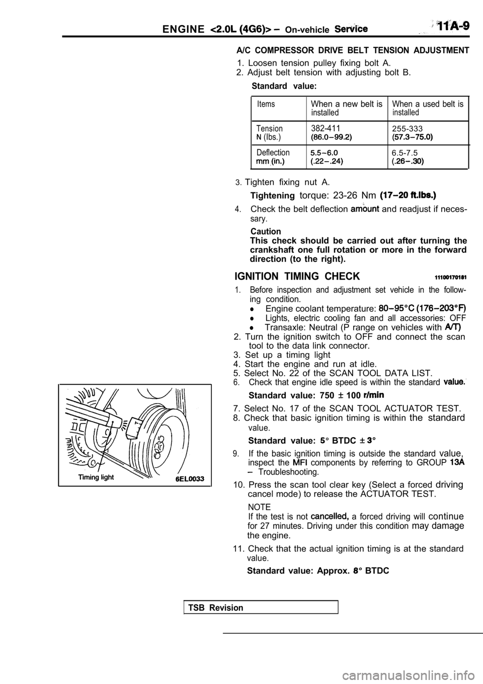
1. Loosen tension pulley fixing bolt A.
2. Adjust belt tension with adjusting bolt B.
Standard value:
Items
Tension
(Ibs.)
Deflection
When a new belt isWhen a used belt is
installedinstalled
382-411255-333
6.5-7.5
3. Tighten fixing nut A.
Tightening torque: 23-26 Nm
4.Check the belt deflection and readjust if neces-
sary.
Caution
This check should be carried out after turning the
crankshaft one full rotation or more in the forward
direction (to the right).
IGNITION TIMING CHECK
1.Before inspection and adjustment set vehicle in the follow-
ing condition.
lEngine coolant temperature:
lLights, electric cooling fan and all accessories: OFF
lTransaxle: Neutral (P range on vehicles with
2. Turn the ignition switch to OFF and connect the scan
tool to the data link connector.
3. Set up a timing light
4. Start the engine and run at idle.
5. Select No. 22 of the SCAN TOOL DATA LIST.
6.Check that engine idle speed is within the standard
Standard value: 750 100
7. Select No. 17 of the SCAN TOOL ACTUATOR TEST.
8. Check that basic ignition timing is within the standard
value.
Standard value: BTDC
9.If the basic ignition timing is outside the standar d value,
inspect the components by referring to GROUP
Troubleshooting.
10. Press the scan tool clear key (Select a forced driving
cancel mode) to release the ACTUATOR TEST.
NOTE
If the test is not
a forced driving will continue
for 27 minutes. Driving under this condition may damage
the engine.
11. Check that the actual ignition timing is at the standard
value.
Standard value: Approx. BTDC
TSB Revision
Page 278 of 2103
ENGINE O n - v e h i c l e
Press the scan tool clear key (select aforced driving
cancel mode) to release the ACTUATOR TEST
NOTE
If the test is not a forced driving will continue
for 27 minutes. Driving under this condition may damage
the engine.
Check that the actual ignition timing is at the st andard
value.
Standard value: Approx. BTDC
NOTE
Ignition timing is variable within about even under
normal operating.
2. And it is automatically further advanced by abou t
from BTDC at higher altitudes.
CURB IDLE SPEED CHECK
Before inspection and adjustment, set vehicles in the
following condition.
lEngine coolant temperature:
lLights, electric cooling fan and all accessories: OFF
lTransaxle: Neutral (P range on vehicles with A/T)
2. Turn the ignition switch to OFF and connect the scan
tool to the data link connector.
3. Select No. 17 of the SCAN TOOL ACTUATOR TEST
4. Check the basic ignition timing.
Standard value: BTDC
5. Run the engine at idle for 2 minutes.
6. Select No. 22 of the SCAN TOOL DATA LIST.
7. Check the curb idle speed.
Standard value: 750 100
NOTE
The idle speed is controlled automatically by the i dle air
control system.
8. If the idle speed is outside the standard value, check
the components by referring to GROUP Trou-
bleshooting.
IDLE MIXTURE CHECK
Before inspection, set vehicles in the following co ndition:
lEngine coolant temperature:
lLights, electric cooling fan and all accessories: O FF
lTransaxle: Neutral (P range on vehicles with
2. Turn the ignition switch to OFF and connect the scan
tool to the data link connector.
3. Select No. 17 of the SCAN TOOL ACTUATOR TEST.
4.Check that the basic ignition timing is within the standard
value..
Standard value:
TSB Revision
Page 389 of 2103
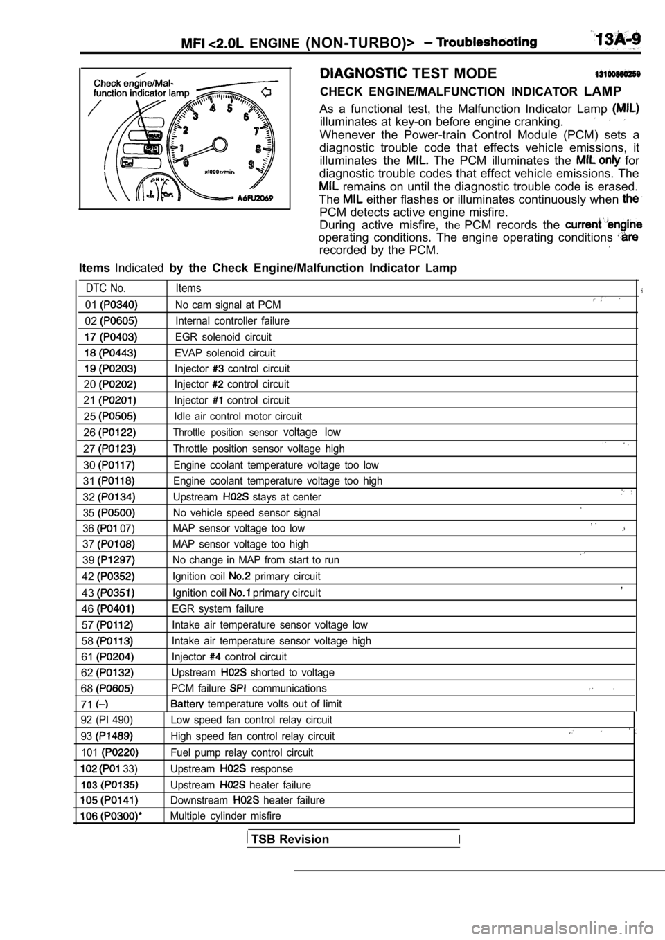
ENGINE (NON-TURBO)>
TEST MODE
CHECK ENGINE/MALFUNCTION INDICATOR LAMP
As a functional test, the Malfunction Indicator Lam p
illuminates at key-on before engine cranking.
Whenever the Power-train Control Module (PCM) sets a
diagnostic trouble code that effects vehicle emissi ons, it
illuminates the
The PCM illuminates the for
diagnostic trouble codes that effect vehicle emissi ons. The
remains on until the diagnostic trouble code is erased.
The
either flashes or illuminates continuously when
PCM detects active engine misfire.
During active misfire, thePCM records the
operating conditions. The engine operating conditio ns
recorded by the PCM.
ItemsIndicated by the Check Engine/Malfunction Indicator Lamp
DTC No. Items
01No cam signal at PCM
02Internal controller failure
EGR solenoid circuit
EVAP solenoid circuit
Injector control circuit
20Injector control circuit
21Injector control circuit
25Idle air control motor circuit
26Throttle position sensor voltage low
27Throttle position sensor voltage high
30Engine coolant temperature voltage too low
31Engine coolant temperature voltage too high
32Upstream stays at center
35
No vehicle speed sensor signal
36
07) MAP sensor voltage too low
37MAP sensor voltage too high
39No change in MAP from start to run
42Ignition coil primary circuit
43Ignition coil primary circuit
46
EGR system failure
57Intake air temperature sensor voltage low
58Intake air temperature sensor voltage high
61Injector control circuit
62Upstream shorted to voltage
68PCM failure communications
71 temperature volts out of limit
, .
,
92 (PI 490)
93
101
33)
103
Low speed fan control relay circuit
High speed fan control relay circuit
Fuel pump relay control circuit
Upstream
response
Upstream
heater failure
Downstream
heater failure
Multiple cylinder misfire
TSB RevisionI
Page 393 of 2103
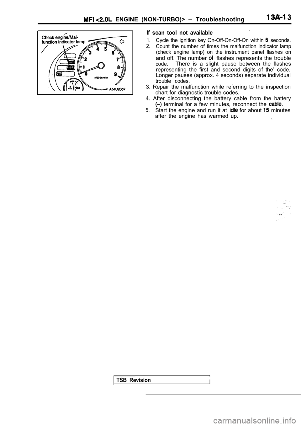
ENGINE (NON-TURBO)> Troubleshooting 3
If scan tool not available
1.Cycle the ignition key On-Off-On-Off-On within seconds.
2.Count the number of times the malfunction indicator lamp
(check engine lamp) on the instrument panel flashes on
and off. The number flashes represents the trouble
code.There is a slight pause between the flashes
representing the first and second digits of the’ co de.
Longer pauses (approx. 4 seconds) separate individu al
,
trouble codes.
3. Repair the malfunction while referring to the in spection
chart for diagnostic trouble codes.
4. After disconnecting the battery cable from the b attery
terminal for a few minutes, reconnect the
5.Start the engine and run it at for about minutes
after the engine has warmed up.
TSB RevisionI
Page 423 of 2103
![MITSUBISHI SPYDER 1990 Service Repair Manual ENGINE Troubleshooting
General scan toolNo Change in MAP From Start to
[Comment]
Background
l The MAP sensor is mounted to intake manifold vacuum .
lThis information provides a MITSUBISHI SPYDER 1990 Service Repair Manual ENGINE Troubleshooting
General scan toolNo Change in MAP From Start to
[Comment]
Background
l The MAP sensor is mounted to intake manifold vacuum .
lThis information provides a](/img/19/57345/w960_57345-422.png)
ENGINE Troubleshooting
General scan toolNo Change in MAP From Start to
[Comment]
Background
l The MAP sensor is mounted to intake manifold vacuum .
lThis information provides an important PCM input fo r determining fuel injector pulse wide.lThe sensor should measure a difference in manifold pressure between key ON and after
the engine is running.
Range of Check
l Vehicle is not moving
l
Engine: The engine idle speed is almost identical t o the target idle speed while the engineis idling.
Set Condition
l Diagnostic trouble code (DTC) memory is not deleted even after the ignition switch is
turned off.
l The difference between the two following MAP values is small.
The value immediately after the ignition switch is turned to ON.
The value while the
is at idle for two seconds.
Ice in sensorl Sensor failedl . failed
Measure at the MAP sensor connector l
Disconnect the connector, and measure at the harnes s side.
l Continuity between and ground.
OK: Continuitv
Check the
Check the harness wire between the PCM and the MAP sensor
connector. if
Check the following connectors: Repair
OK
Check trouble symptom.
N G N G
Check the harness wire between the PCM and the MAP
connector.
OK
.
Replace the MAP sensor.
TSB Revision
Page 439 of 2103
![MITSUBISHI SPYDER 1990 Service Repair Manual ENGINE (NON-TURBO)>
Scan tool 103
Code General scan tool
No.Upstream Failure
21
[Comment]
Background
l The PCM continues to monitor this system after the key is OFF.
l The PCM MITSUBISHI SPYDER 1990 Service Repair Manual ENGINE (NON-TURBO)>
Scan tool 103
Code General scan tool
No.Upstream Failure
21
[Comment]
Background
l The PCM continues to monitor this system after the key is OFF.
l The PCM](/img/19/57345/w960_57345-438.png)
ENGINE (NON-TURBO)>
Scan tool 103
Code General scan tool
No.Upstream Failure
21
[Comment]
Background
l The PCM continues to monitor this system after the key is OFF.
l The PCM waits some periods to allow the heated oxyg en sensors to cool.
l Once the PCM calculates that the heated oxygen sens or is cooled, it energizes the
relay (ASD relay) and tests for the heated oxygen sensor operation.
Range of Check
5 seconds or more after turning the ignition switch to OFF. Battery positive voltage: or morelThe heated oxygen sensor output line voltage rises by 0.49 or more within 144 secondsafter turning the ignition switch to OFF. The initial rise of the output line voltage is less than 1.57 V.Set ConditionHeated oxygen sensor’s circuit does not show the ap propriate decrease of voltage the test.
l Heated oxygen sensor heater open l harness and connectors ,
Measure at the heated oxygen sensor (front) connect or l
Disconnect the connector, and measure at the harnes s side.
SCAN TOOL Actuator test
relay (ASD relay) Check the following connector: everyapprox. 1. Voltage between 4 and ground
[Measure with the relay (ASD relay) on]
OK: Battery positive voltage Check the harness wire between the and
2. Continuity between 3 and ground the heated oxygen sensor connector. if
OK: Continuity
2. NG Check the harness wire between the heated oxygen sensor and
OKthe ground. Repair, if necessary.
NGCheck the followingconnect Repair
OK
Check trouble symptom.
NG
Replace the heated oxygen sensor (front).
TSB Revision
Page 440 of 2103
![MITSUBISHI SPYDER 1990 Service Repair Manual E N G I N E
[Comment]
Background
l The PCM continues to monitor this system after the key is OFF.
l The PCM waits some periods to allow the heated oxyg en sensors to cool. MITSUBISHI SPYDER 1990 Service Repair Manual E N G I N E
[Comment]
Background
l The PCM continues to monitor this system after the key is OFF.
l The PCM waits some periods to allow the heated oxyg en sensors to cool.](/img/19/57345/w960_57345-439.png)
E N G I N E
[Comment]
Background
l The PCM continues to monitor this system after the key is OFF.
l The PCM waits some periods to allow the heated oxyg en sensors to cool.
l Once the PCM calculates that the heated oxygen sens or is cooled, it energizes the
relay relay) and tests for the heated oxygen sensor operation.
Range of Check
l 5 seconds or more after turning the ignition switch to OFF.
l Battery positive voltage: 10
or morelThe heated oxygen sensor output line voltage rises by 0.49 or more within 144 secondsafter turning the ignition switch to OFF. The initial of the output line voltage is less than 1.57 V.Set ConditionHeated oxygen sensor’s circuit does not show the ap propriate decrease of voltage the test.
1. NG
Measure at the heated oxygen sensor (rear) connecto r
lDisconnect the connector, and measure at the harnes s side.
SCAN TOOL Actuator test 10
relay (ASD relay) everyapprox. 1. Voltage between 3 and ground [Measure with the relay
(ASD relay) on]
OK: Battery positive voltage
2. Continuity between 4 and ground
OK: Continuity
OK
2. NG l
Heated oxygen sensor heater
l harness and
. .
Check the harness wire between (ASP the heated oxygen sensor
Check the harness wire between the heated oxygen s ensor and
the ground. Repair, if necessary.
NG Repair
Check trouble symptom.
OK
NG
Replace the heated oxygen sensor (rear).
TSB Revision
Page 501 of 2103
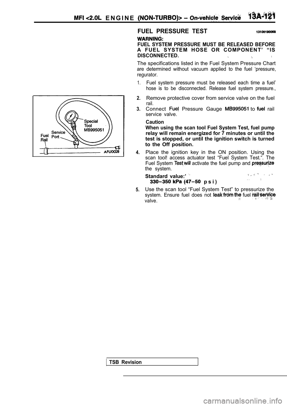
E N G I N E ,
FUEL PRESSURE TEST
FUEL SYSTEM PRESSURE MUST BE RELEASED BEFORE
A F U E L S Y S T E M H O S E O R C O M P O N E N T ’ “ I S
DISCONNECTED.
The specifications listed in the Fuel System Pressure Chart
are determined without vacuum applied to the fuel ‘ pressure,
regurator.
1.
2.
3.
4.
5.
Fuel system pressure must be released each time a f uel’
hose is to be disconnected. Release fuel system pre ssure.,
Remove protective cover from service valve on the fuel
rail.
Connect Pressure Gauge to rail
service valve.
Caution
When using the scan tool Fuel System Test, fuel pum p
relay will remain energized for 7 minutes or until the
test is stopped, or until the ignition switch is tu rned
to the Off position.
Place the ignition key in the ON position. Using th e
scan tool! access actuator test “Fuel System Test.“. The
Fuel System
activate the fuel pump and
the system.
Standard value:’
p s i )
Use the scan tool “Fuel System Test” to pressurize the
system. Ensure fuel does not fuel
valve.
TSB Revision