ad blue MITSUBISHI SPYDER 1990 Service Repair Manual
[x] Cancel search | Manufacturer: MITSUBISHI, Model Year: 1990, Model line: SPYDER, Model: MITSUBISHI SPYDER 1990Pages: 2103, PDF Size: 68.98 MB
Page 158 of 2103
11 E N G I N E O V E R H A U L Piston and
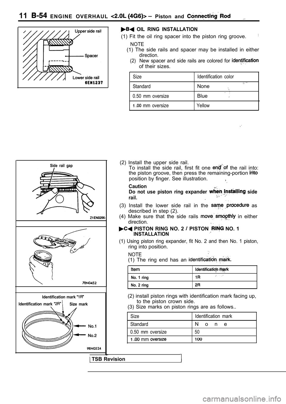
Side rail gap
Identification mark
Identification mark Size mark
OIL RING INSTALLATION
(1) Fit the oil ring spacer into the piston ring groove.
NOTE
(1) The side rails and spacer may be installed in e ither
direction.
(2)
New spacer and side rails are colored for
of their sizes.
Size
Standard
0.50 mm oversize
1 mm oversize Identification color
None
Blue
Yellow
(2) Install the upper side rail.
To install the side rail, first fit one
the rail into:
the piston groove, then press the remaining-portion
position by finger. See illustration. ,
Caution
Do not use piston ring expander side
rail.
(3) Install the lower side rail in the as
described in step (2).
(4) Make sure that the side rails
in either
direction.
PISTON RING NO. 2 PISTON NO. 1
INSTALLATION
(1) Using piston ring expander, fit No. 2 and then No. 1 piston,
ring into position.
NOTE
(1) The ring end has an
No. 1 ring
No. 2 ring
(2) install piston rings with identification mark facing up,
to the piston crown side.
(3) Size marks on piston rings are as follows..
Size
Standard
0.50 mm oversize
1 mm
Identification mark
N o n e
50
TSB Revision
Page 243 of 2103
(Overall)
Intake 111.49-111.99 mm (4.389-4.499 in.) Exhaust
mm in.)
Stem Diameter
Intake 5.934-5.952 mm in.)
Exhaust
mm in.)
Valve Margin
Intake 1.285-1.615 mm in.)
Exhaust
mm in.)
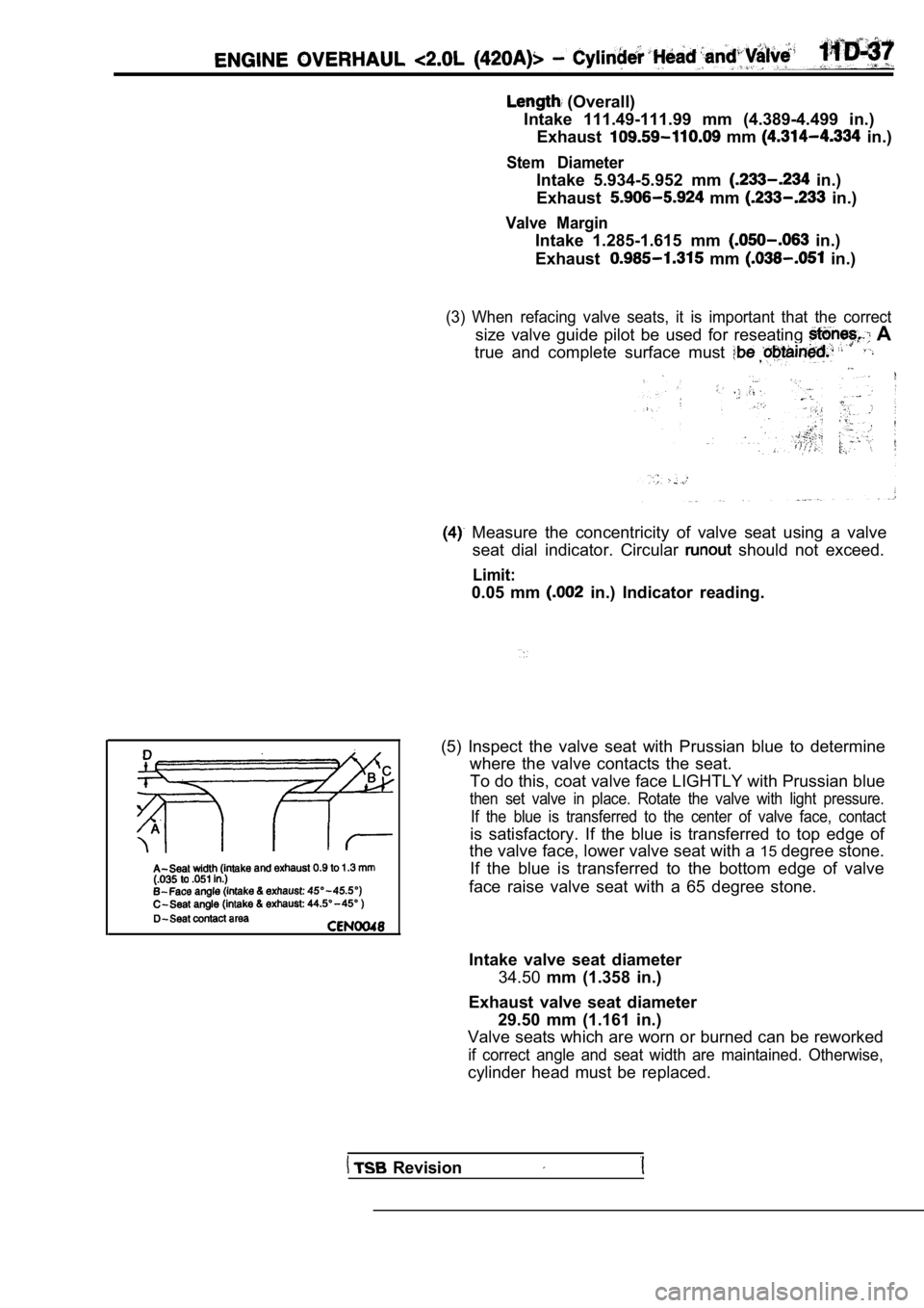
(3) When refacing valve seats, it is important that the correct
size valve guide pilot be used for reseating A
true and complete surface must
Measure the concentricity of valve seat using a va lve
seat dial indicator. Circular
should not exceed.
Limit:
0.05 mm in.) Indicator reading.
(5) Inspect the valve seat with Prussian blue to de termine
where the valve contacts the seat.
To do this, coat valve face LIGHTLY with Prussian b lue
then set valve in place. Rotate the valve with light pressure.
If the blue is transferred to the center of valve f ace, contact
is satisfactory. If the blue is transferred to top edge of
the valve face, lower valve seat with a 15degree stone.
If the blue is transferred to the bottom edge of va lve
face raise valve seat with a 65 degree stone.
Intake valve seat diameter 34.50 mm (1.358 in.)
Exhaust valve seat diameter 29.50 mm (1.161 in.)
Valve seats which are worn or burned can be reworke d
if correct angle and seat width are maintained. Otherwise,
cylinder head must be replaced.
Revision
Page 638 of 2103
Analyzer
STEPPER MOTOR Engine (Turbo)>
Measurement method
1. Disconnect the stepper motor connector, and connect
the special tool (test harness:
in between.
2. Connect the analyzer special patterns pickup to the step-
per motor-side connector terminal (red clip on the special
tool), terminal 3 (blue clip), terminal 4 (black clip) and
terminal 6 (yellow clip) respectively.
Alternate method (Test
not available) .
1. Connect the analyzer special patterns pickup to ECM
terminal 4, connection terminal 5, connection termi nal
17, and’ connection terminal 18 respectively.
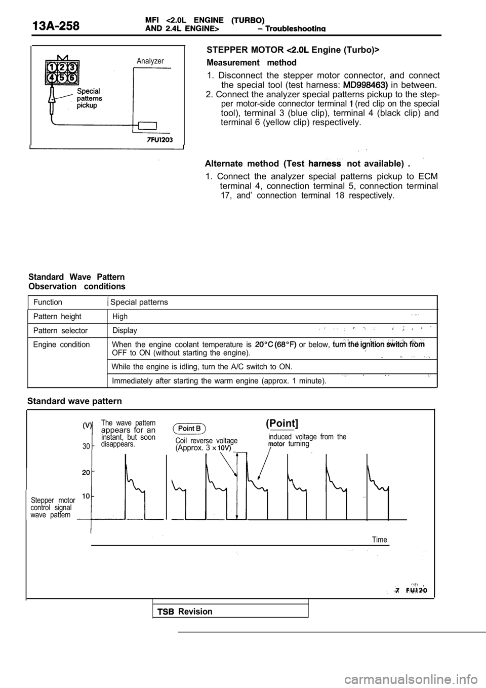
Standard Wave Pattern
Observation conditions
Function Special patterns
Pattern height
Pattern selector
Engine conditionHigh
Display
When the engine coolant temperature is or below,
OFF to ON (without starting the engine)..
While the engine is idling, turn the A/C switch to ON.. .Immediately after starting the warm engine (approx. 1 minute).
Standard wave pattern
The wave patternappears for aninstant, but soon
30disappears.
Stepper motor
10
control signal
wave pattern
Coil reverse voltage(Approx. 3
(Point]
induced voltage from the turning
Time
Revision
Page 663 of 2103
sensor equipmentside connector
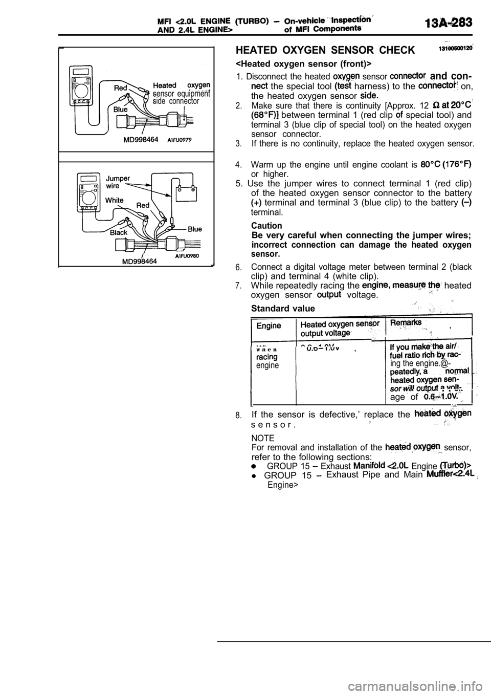
HEATED OXYGEN SENSOR CHECK
1. Disconnect the heated sensor and con-
the special tool harness) to the on,
the heated oxygen sensor
2.Make sure that there is continuity [Approx. 12
between terminal 1 (red clip special tool) and
terminal 3 (blue clip of special tool) on the heate d oxygen
sensor connector.
3.If there is no continuity, replace the heated oxyge n sensor.
4.Warm up the engine until engine coolant is
or higher.
5. Use the jumper wires to connect terminal 1 (red clip)
of the heated oxygen sensor connector to the batter y
terminal and terminal 3 (blue clip) to the battery
terminal.
Caution
Be very careful when connecting the jumper wires;
incorrect connection can damage the heated oxygen
sensor.
6.
7.
8.Connect a digital voltage meter between terminal 2 (black
clip) and terminal 4 (white clip).
While repeatedly racing the
heated
oxygen sensor
voltage.
Standard value
,
w n e n ,
engineing the engine.@-
. .
age of
If the sensor is defective,’ replace the
s e n s o r .
NOTEFor removal and installation of the
sensor,
refer to the following sections:
GROUP 15 Exhaust Engine
l GROUP 15 Exhaust Pipe and Main
Engine>
Page 666 of 2103
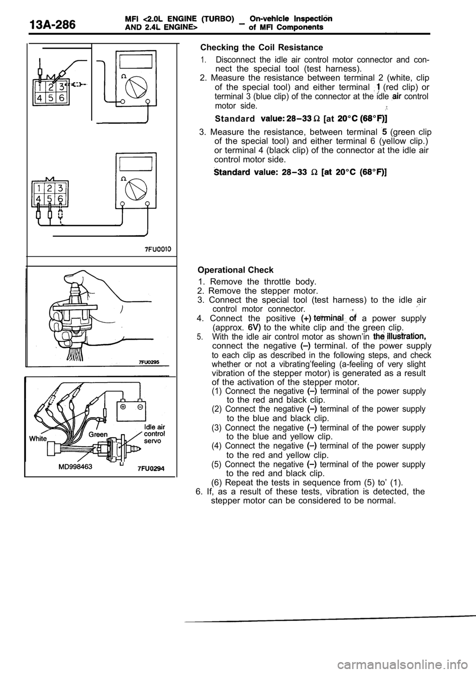
Checking the Coil Resistance
1.Disconnect the idle air control motor connector and con-
nect the special tool (test harness).
2. Measure the resistance between terminal 2 (white , clip
of the special tool) and either terminal
(red clip) or
terminal 3 (blue clip) of the connector at the idle control
motor side.
Standard [at
3. Measure the resistance, between terminal (green clip
of the special tool) and either terminal 6 (yellow clip.)
or terminal 4 (black clip) of the connector at the idle air
control motor side.
Operational Check
1. Remove the throttle body.
2. Remove the stepper motor. 3. Connect the special tool (test harness) to the i dle air
control motor connector.
4. Connect the positive a power supply
(approx.
to the white clip and the green clip.
5.With the idle air control motor as shown’in
connect the negative terminal. of the power supply
to each clip as described in the following steps, a nd check
whether or not a vibrating’feeling (a-feeling of ve ry slight
vibration of the stepper motor) is generated as a r esult
of the activation of the stepper motor.
(1) Connect the negative terminal of the power supply
to the red and black clip.
(2) Connect the negative terminal of the power supply
to the blue and black clip.
(3) Connect the negative terminal of the power supply
to the blue and yellow clip.
(4) Connect the negative terminal of the power supply
to the red and yellow clip.
(5) Connect the negative terminal of the power supply
to the red and black clip.
(6) Repeat the tests in sequence from (5) to’ (1).
6. If, as a result of these tests, vibration is det ected, the
stepper motor can be considered to be normal.
Page 800 of 2103
(Turbo) and Engine>
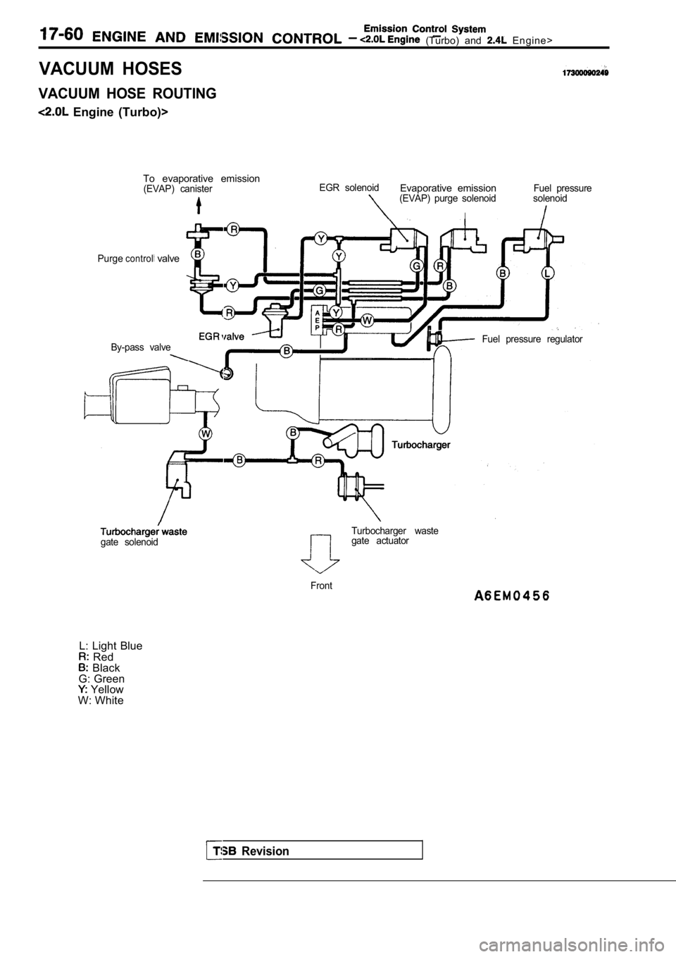
VACUUM HOSES
VACUUM HOSE ROUTING
Engine (Turbo)>To evaporative emission
(EVAP) canisterEGR solenoidEvaporative emissionFuel pressure(EVAP) purge solenoid solenoid
I
Purgecontrol valve
By-pass valveFuel pressure regulator
Revision
Turbocharger waste
gate solenoidgate actuator
Front
L: Light Blue Red Black
G: Green
Yellow
W: White
Page 801 of 2103
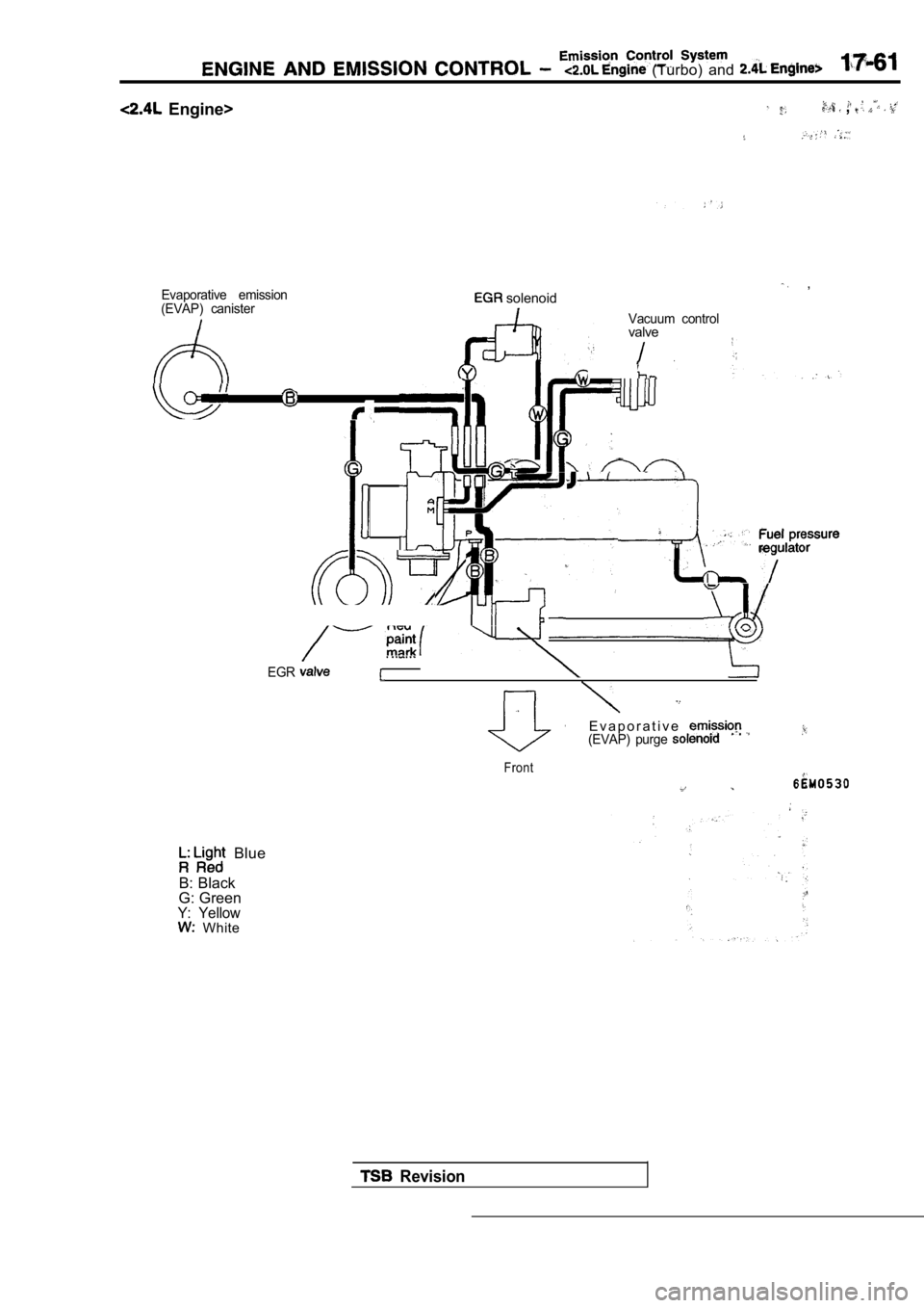
Evaporative emission
(EVAP) canister , solenoid
Vacuum controlvalve
EGR
E v a p o r a t i v e(EVAP) purge
Front
(Turbo) and
Engine> ,
Blue
B: Black
G: Green
Y: Yellow White
Revision
Page 802 of 2103
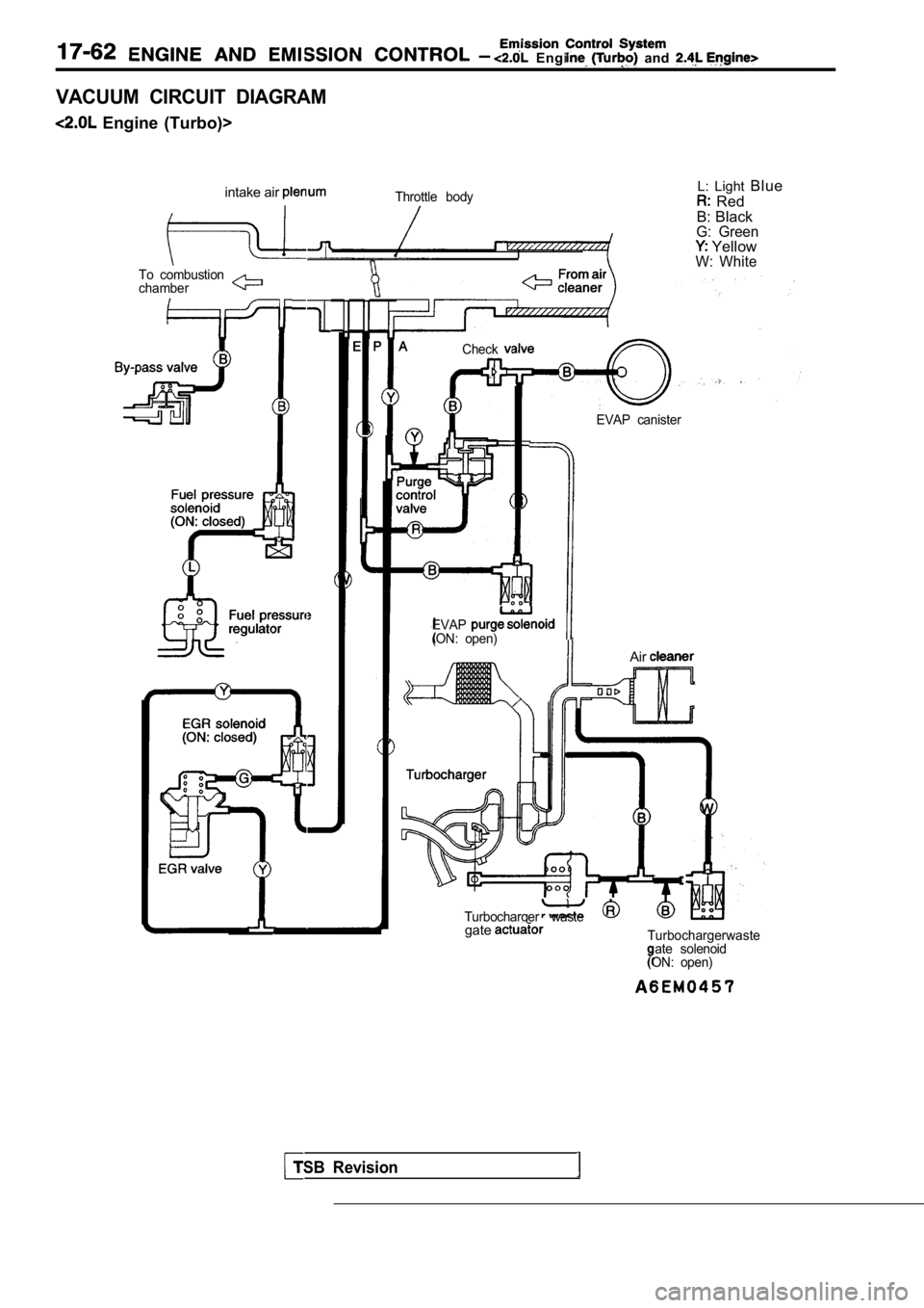
Engine and
VACUUM CIRCUIT DIAGRAM
Engine (Turbo)>intake air
Throttle bodyL: Light Blue
Red
B: Black
G: Green YellowW: WhiteTo combustion
chamber
Check
EVAP(ON: open)
EVAP canister
TSB Revision
Air
Turbocharger wastegateTurbochargerwasteate solenoid
ON: open)
Page 897 of 2103
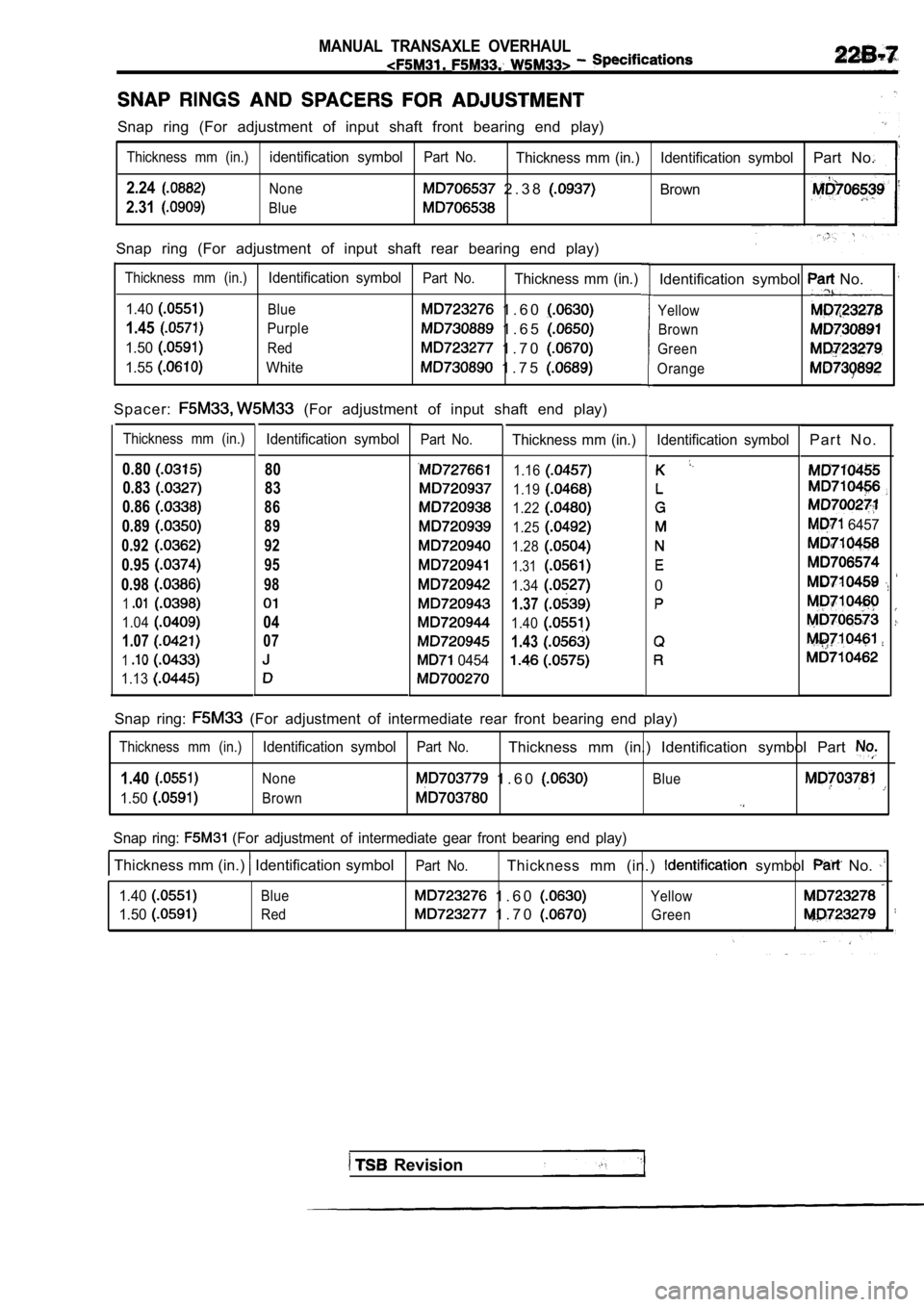
MANUAL TRANSAXLE OVERHAUL
Snap ring (For adjustment of input shaft front bearing end play)
Thickness mm (in.)identification symbolPart No.Thickness mm (in.) Identification symbolPart No.
2.24None 2 . 3 8 Brown
2.31Blue
Snap ring (For adjustment of input shaft rear beari ng end play)
Thickness mm (in.)Identification symbolPart No.Thickness mm (in.)
1.40
Blue 1 . 6 0
1.45Purple 1 . 6 5
1.50Red 1 . 7 0
1.55White 1 . 7 5
S p a c e r : (For adjustment of input shaft end play)
Thickness mm (in.)Identification symbol
0.8080
0.83
83
0.86
86
0.8989
0.92
92
0.9595
0.9898
1
1.0404
1.0707
1
1.13
Part No.
0454
Thickness mm (in.)
1.16
1.19
1.22
1.25
1.28
1.31
1.34
1.37
1.40
1.43
Identification symbol No.
Yellow
Brown
Green
Orange
Identification symbol
0
Snap ring: (For adjustment of intermediate rear front bearing end play)P a r t N o .
6457
Thickness mm (in.)Identification symbolPart No.Thickness mm (in.) Identification symbol Part
1.40None 1 . 6 0 Blue
1.50Brown
Snap ring: (For adjustment of intermediate gear front bearing
end play)
Thickness mm (in.) Identification symbol
1.40
1.50
Blue
RedPart No.
Thickness mm (in.) symbol No.
1 . 6 0 Yellow
1 . 7 0 Green
Revision
Page 900 of 2103
![MITSUBISHI SPYDER 1990 Service Repair Manual MANUAL TRANSAXLE OVERHAUL
Snap ring: [For adjustment of viscous coupling end play (with VCU)]
Thickness mm (in.)Identification symbolPart No. Thickness mm (in.) Identification sym MITSUBISHI SPYDER 1990 Service Repair Manual MANUAL TRANSAXLE OVERHAUL
Snap ring: [For adjustment of viscous coupling end play (with VCU)]
Thickness mm (in.)Identification symbolPart No. Thickness mm (in.) Identification sym](/img/19/57345/w960_57345-899.png)
MANUAL TRANSAXLE OVERHAUL
Snap ring: [For adjustment of viscous coupling end play (with VCU)]
Thickness mm (in.)Identification symbolPart No. Thickness mm (in.) Identification symbolPart No.
1.3
1.4
1.5
1.6
Orange
Red
Blue
None
1.7
1.8
1.9
White
Yellow
Green
Spacer: (For adjustment of center differential pinion back lash front side)
Thickness mm (in.)Identification symbolPart No.Thickness mm (in.)Identification symbolPart No.
2.25-2.32
2.33-2.42
412
410
409
2.59-2.66
2.67-2.74
2.75-2.82
4 3
2
408
407
405
Spacer: (For adjustment of center differential case preloa d)
Thickness mm (in.)Identification symbol
1.13
13
1.1616
1.1919
1.222 2
1.2525
1.2828
1.3131
1.3737
1.4040
1.43
43
1.4646 Part No.
66
8520
8522
8523
Revision
Thickness mm (in.)
Identification symbolPart No.
1.49
49 8524
1.5252 8525
1.5555 8526
1.5858 8527
1.6161 8528
1.6464 8529
1.6787 8530
1.7070 8531
1.73
73 959
1.7676 960
1.7979
Spacer: (For adjustment of center differential pinion back lash, rear side)
Thickness mm (in.)IdentificationPart No.Thickness mm (in.)Identification symbol No.
74 1 78
501 1.0876
8077
7949