battery location MITSUBISHI SPYDER 1990 Service Repair Manual
[x] Cancel search | Manufacturer: MITSUBISHI, Model Year: 1990, Model line: SPYDER, Model: MITSUBISHI SPYDER 1990Pages: 2103, PDF Size: 68.98 MB
Page 22 of 2103

GENERAL before Service
PRECAUTIONS BEFORE SERVICE.
SUPPLEMENTAL RESTRAINT SYSTEM
1. to follow when servicing SRS
(1) Be sure to read GROUP Supplemental Restraint System
For safe operations, please follow the directions a nd heed all
(2) Always use the designated special tools and tes t equipment.
(3) Wait at least 60 seconds after disconnecting the battery cable before” further work;
The SRS system is designed to retain enough voltage to deploy the air bag even after the battery
has been disconnected. Serious injury may result from unintended air bag deployment if work
is done on the SRS system immediately after the bat tery cable is disconnected.
(4) Never attempt to disassemble or repair the SRS components (SRS-ECU air bag module and
clock spring). If faulty, replace it.
(5) Warning labels must be heeded when servicing or handling SRS components. Warning labels
are located in the following locations.
Sun visor
l Glove box
. S R S - E C U
l Steering wheel
l Air bag module
l Clock spring
l Steering gear and linkage clamp
(6) Store components removed from the SRS
a clean and dry place.
The air bag module should be stored on a flat surfa ce and placed so that the pad surface is’
facing upward.
Do not place anything on top of it.
(7) Be sure to deploy the air bag before disposing of the air bag’module or disposing of a vehicle
equipped with an air bag. (Refer to GROUP
Air Bag Module Disposal Procedures.)
(8) Whenever you finish servicing the
check the SRS warning light operation to make sure
that the system functions properly.
2.Observe the following when carrying out operations on places where SRS components are installed,’
.,
including operations not directly related to the SR S air bag.
(1) When removing or installing parts do not allow any impact or shock to the SRS components.
(2) SRS components should not be subjected to heat over so remove the SRS compo-
nents before drying or baking the vehicle after painting.
After re-installing them, check the SRS warning lig ht operation to make sure that the system
functions properly.
SERVICING THE ELECTRICAL SYSTEM
1. Note the following before proceeding with work o n the
electrical system.
Note that the following must never be done:
Unauthorized modifications of any electrical device or
wiring, because such modifications might lead to a vehicle
malfunction, over-capacity or short-circuit that co uld result
in a fire in the vehicle.
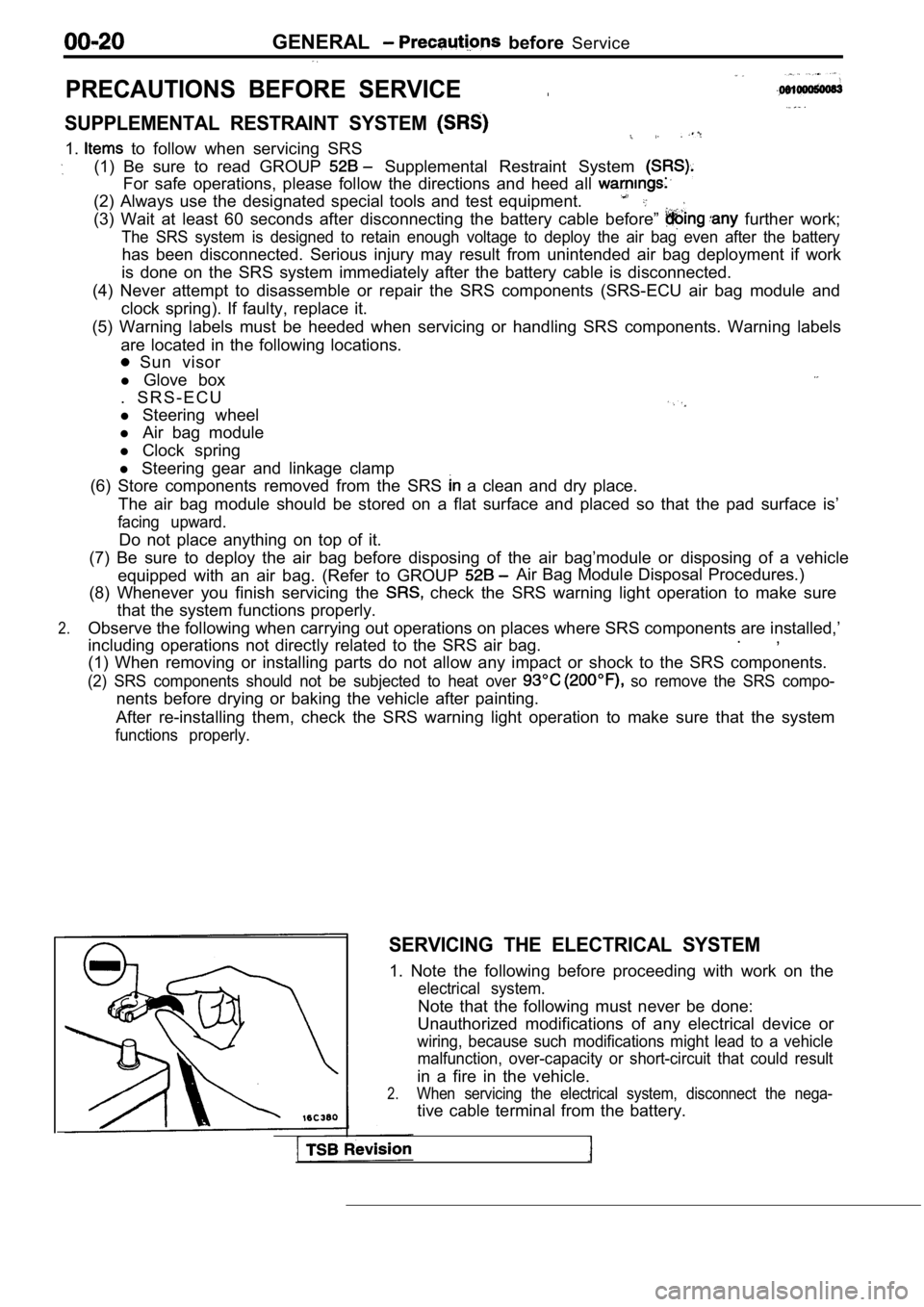
2.When servicing the electrical system, disconnect th e nega-
tive cable terminal from the battery.
Page 2037 of 2103

SRS Air Baa Module Disposal
Body wiring harness
Air bag (red) connector
Connection
Insulation
side>
passenger’s
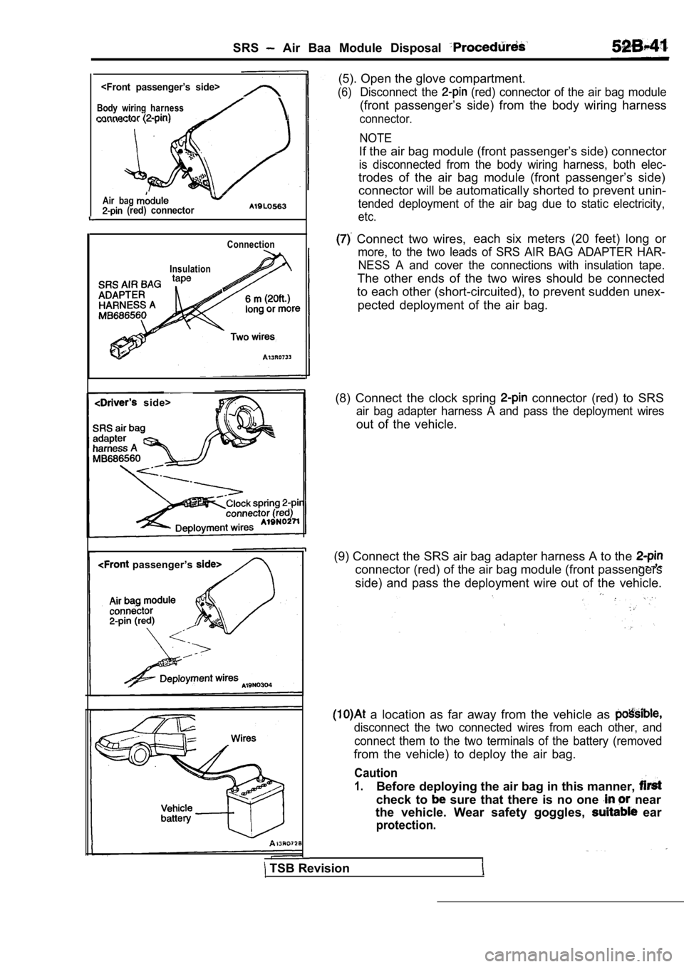
TSB Revision (5). Open the glove compartment.
(6)Disconnect the (red) connector of the air bag module
(front passenger’s side) from the body wiring harne
ss
connector.
NOTE
If the air bag module (front passenger’s side) connector
is disconnected from the body wiring harness, both elec-
trodes of the air bag module (front passenger’s side)
connector will be automatically shorted to prevent unin-
tended deployment of the air bag due to static elec tricity,
etc.
Connect two wires,each six meters (20 feet) long or
more, to the two leads of SRS AIR BAG ADAPTER HAR-
NESS A and cover the connections with insulation ta pe.
The other ends of the two wires should be connected
to each other (short-circuited), to prevent sudden unex-
pected deployment of the air bag.
(8) Connect the clock spring
connector (red) to SRS
air bag adapter harness A and pass the deployment w ires
out of the vehicle.
(9) Connect the SRS air bag adapter harness A to th e
connector (red) of the air bag module (front passengers
side) and pass the deployment wire out of the vehic le.
a location as far away from the vehicle as
disconnect the two connected wires from each other, and
connect them to the two terminals of the battery (r emoved
from the vehicle) to deploy the air bag.
Caution
1.Before deploying the air bag in this manner,
check to sure that there is no one near
the vehicle. Wear safety goggles,
ear
protection.
Page 2039 of 2103

SRS Air Bag Module Disposal Procedures
Wires
Air bag module
Tires without wheels
battery
Air bag module
wire
side>
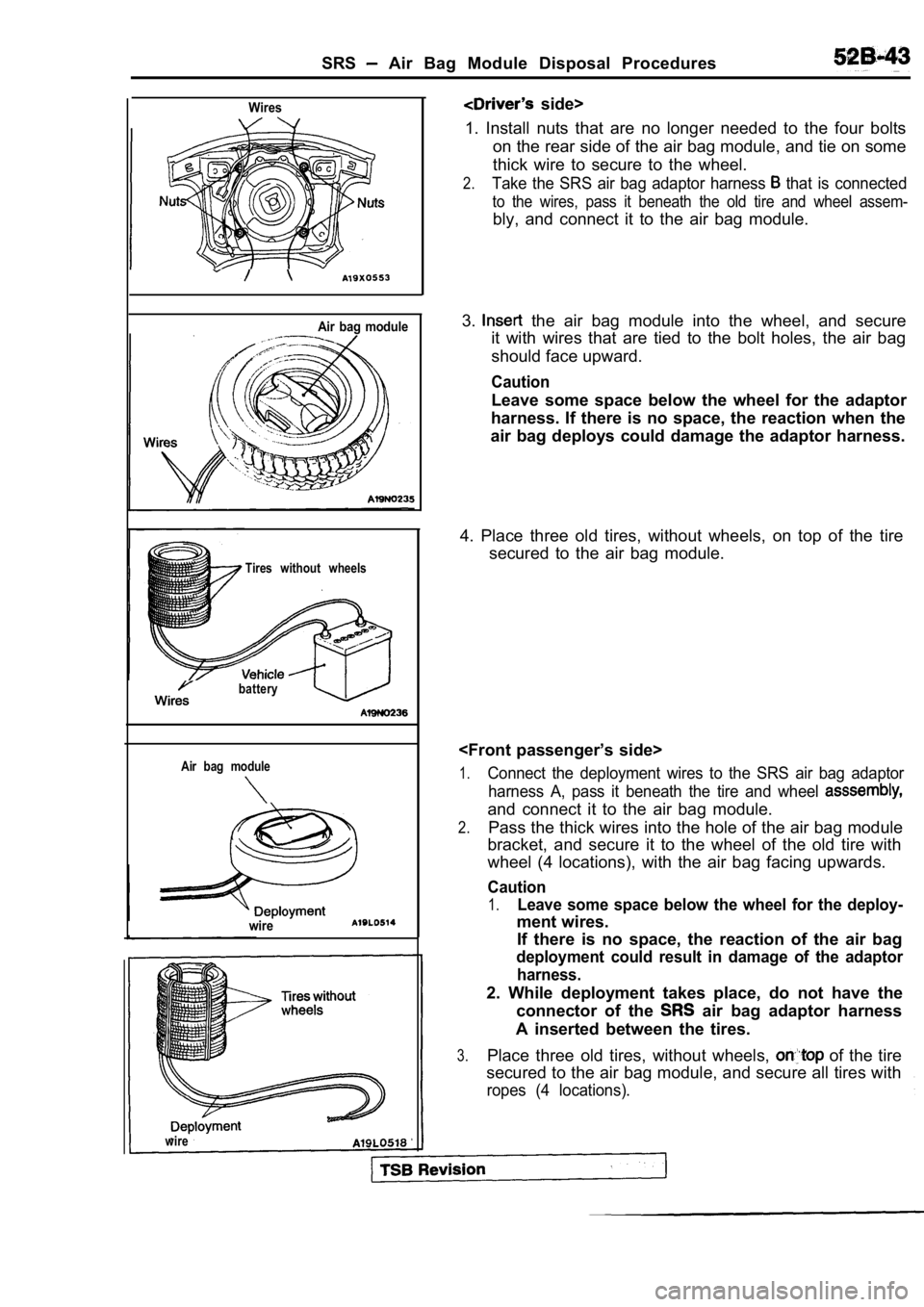
1. Install nuts that are no longer needed to the fo ur bolts
on the rear side of the air bag module, and tie on some
thick wire to secure to the wheel.
2.Take the SRS air bag adaptor harness that is connected
to the wires, pass it beneath the old tire and whee l assem-
bly, and connect it to the air bag module.
3.
the air bag module into the wheel, and secure
it with wires that are tied to the bolt holes, the air bag
should face upward.
Caution
Leave some space below the wheel for the adaptor
harness. If there is no space, the reaction when th e
air bag deploys could damage the adaptor harness.
4. Place three old tires, without wheels, on top of the tire
secured to the air bag module.
1.Connect the deployment wires to the SRS air bag ada ptor
harness A, pass it beneath the tire and wheel
and connect it to the air bag module.
2.Pass the thick wires into the hole of the air bag m odule
bracket, and secure it to the wheel of the old tire with
wheel (4 locations), with the air bag facing upward s.
Caution
1.Leave some space below the wheel for the deploy-
ment wires.
If there is no space, the reaction of the air bag
deployment could result in damage of the adaptor
harness.
2. While deployment takes place, do not have the connector of the
air bag adaptor harness
A inserted between the tires.
3.Place three old tires, without wheels, of the tire
secured to the air bag module, and secure all tires with
ropes (4 locations).
wire
Page 2040 of 2103

SRS Air Baa Module Procedures
Strong
bag module
At alocation as far away from the air bag as
possible, and from a shielded position, if possible , discon-
nect the two connected wires from each other and co nnect
them to the two terminals of- the battery (removed from
the vehicle) to deploy the air bag.
Caution
1. Before deployment, check carefully to be sure that no one is nearby.
2.The inflator will be quite hot immediately followin g’
deployment, so wait at least 30 minutes to allow
it to cool before attempting. to handle it.
Although not poisonous, do not inhale gas from
air bag deployment. See Deployed Air Bag Module
Disposal Procedures for post-deploy-
ment handling instructions.
3. If the air bag module fails to deploy when the
procedures above are followed, do not go near
the module. Contact the MMSA Tech. Line.
5.Dispose of the air bag module after according
to the Deployed Air Bag Module Disposal Procedures (Refer to
DEPLOYED AIR BAG DISPOSAL
After deployment, the air bag module should be
of in the same manner as any other scrap parts, exc ept
the following points should be carefully noted during disposal.
(1) The inflator will be quite hot immediately foll owing
ment, so wait at least 30 minutes to allow it to co ol before
attempting to handle it.
(2) Do not put water or oil on the air bag after de ployment.
(3) There may be, adhered to the deployed air bag module,
material that could irritate the eyes
skin, so wear
gloves and safety goggles when handling a deployed
air bag module. IF DESPITE THESE PRECAUTIONS,
THE MATERIAL DOES, GET INTO
OR ON
THE SKIN, IMMEDIATELY RINSE THE AFFECTED AREA
WITH A LARGE AMOUNT OF CLEAN WATER. IF ANY
IRRITATION DEVELOPS, SEEK ATTENTION.
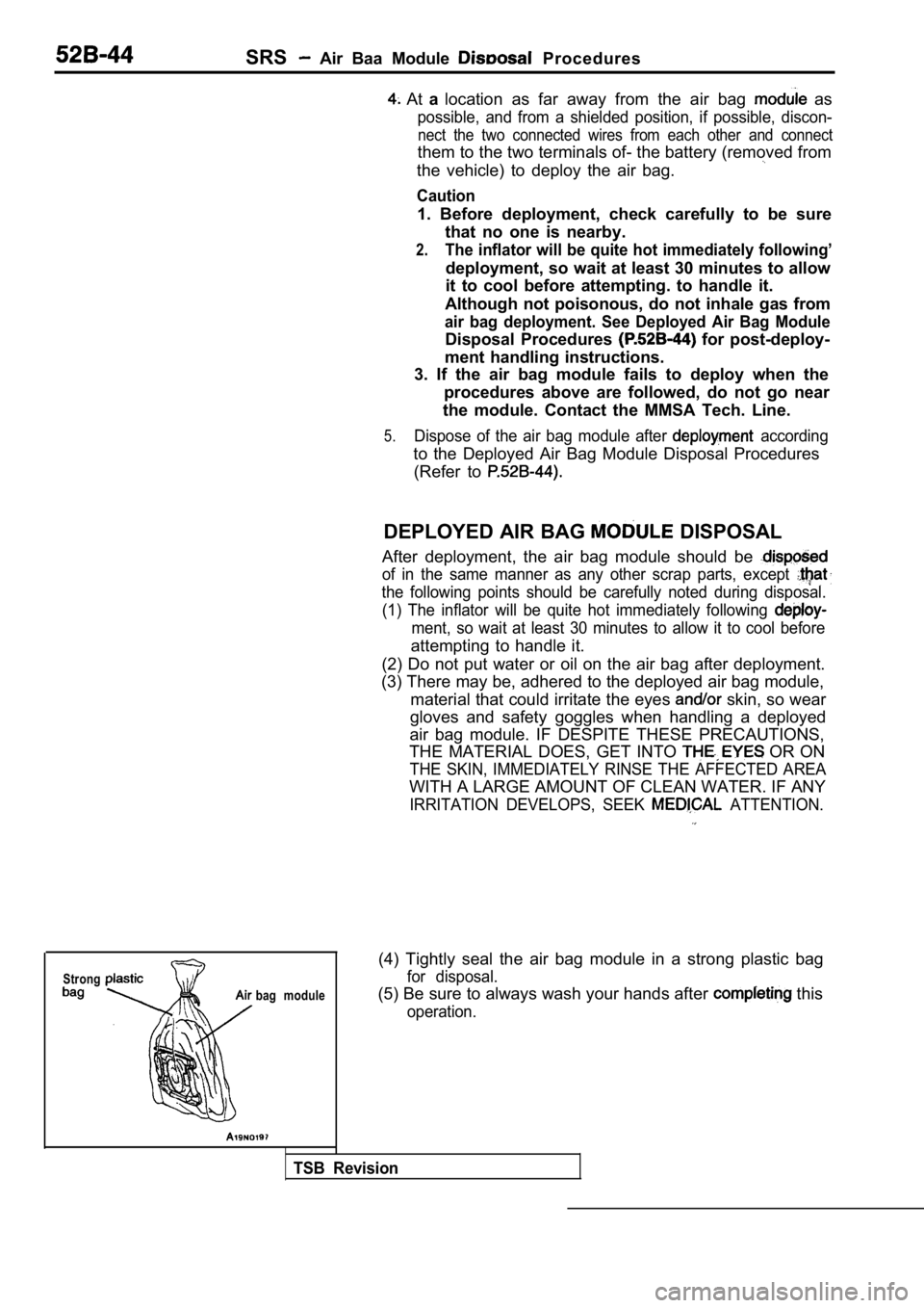
(4) Tightly seal the air bag module in a strong pla stic bag
for disposal.
(5) Be sure to always wash your hands after this
operation.
TSB Revision