brake fluid MITSUBISHI SPYDER 1990 Service Repair Manual
[x] Cancel search | Manufacturer: MITSUBISHI, Model Year: 1990, Model line: SPYDER, Model: MITSUBISHI SPYDER 1990Pages: 2103, PDF Size: 68.98 MB
Page 3 of 2103
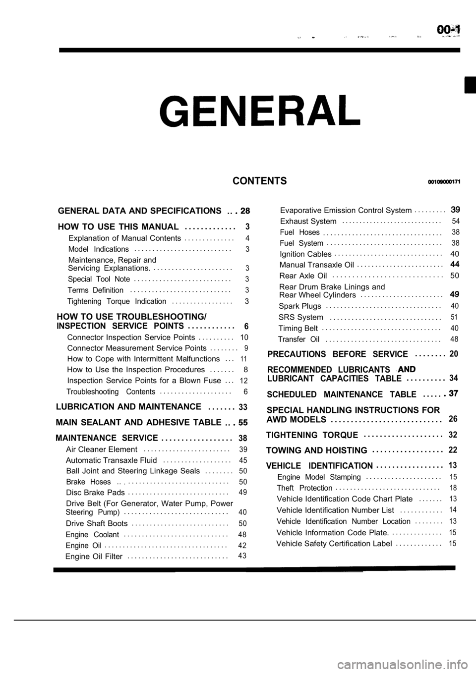
CONTENTS
GENERAL DATA AND SPECIFICATIONS. .
HOW TO USE THIS MANUAL. . . . . . . . . . . . .3
Explanation of Manual Contents. . . . . . . . . . . . . .4
Model Indications
. . . . . . . . . . . . . . . . . . . . . . . . . . .3
Maintenance, Repair and
Servicing Explanations. . . . . . . . . . . . . . . . . . . . . . .
3
Special Tool Note. . . . . . . . . . . . . . . . . . . . . . . . . . .3
Terms Definition. . . . . . . . . . . . . . . . . . . . . . . . . . . .3
Tightening Torque Indication. . . . . . . . . . . . . . . . .3
HOW TO USE TROUBLESHOOTING/
INSPECTION SERVICE POINTS. . . . . . . . . . . .6
Connector Inspection Service Points
. . . . . . . . . .10
Connector Measurement Service Points . . . . . . . .9
How to Cope with Intermittent Malfunctions . . .11
How to Use the Inspection Procedures
. . . . . . .
8
Inspection Service Points for a Blown Fuse . . .
12
Troubleshooting Contents. . . . . . . . . . . . . . . . . . . .6
LUBRICATION AND MAINTENANCE . . . . . . .33
MAIN SEALANT AND ADHESIVE TABLE
. .
MAINTENANCE SERVICE. . . . . . . . . . . . . . . . . .38
Air Cleaner Element. . . . . . . . . . . . . . . . . . . . . . . .39
Automatic Transaxle Fluid
. . . . . . . . . . . . . . . . . . .45
Ball Joint and Steering Linkage Seals
. . . . . . . .50
Brake Hoses.... . . . . . . . . . . . . . . . . . . . . . . . . . . .50
Disc Brake Pads. . . . . . . . . . . . . . . . . . . . . . . . . . . .49
Drive Belt (For Generator, Water Pump, Power
Steering Pump). . . . . . . . . . . . . . . . . . . . . . . . . . . . .40
Drive Shaft Boots
. . . . . . . . . . . . . . . . . . . . . . . . . . .50
Engine Coolant. . . . . . . . . . . . . . . . . . . . . . . . . . . . .48
Engine Oil. . . . . . . . . . . . . . . . . . . . . . . . . . . . . . . . . .42
Engine Oil Filter. . . . . . . . . . . . . . . . . . . . . . . . . . . .43
Evaporative Emission Control System . . . . . . . . .
Exhaust System. . . . . . . . . . . . . . . . . . . . . . . . . . . . .54
Fuel Hoses. . . . . . . . . . . . . . . . . . . . . . . . . . . . . . . . .38
Fuel System. . . . . . . . . . . . . . . . . . . . . . . . . . . . . . . .38
Ignition Cables. . . . . . . . . . . . . . . . . . . . . . . . . . . . . .
40
Manual Transaxle Oil . . . . . . . . . . . . . . . . . . . . . . . .
Rear Axle Oil. . . . . . . . . . . . . . . . . . . . . . . . . . . .
50
Rear Drum Brake Linings and
Rear Wheel Cylinders . . . . . . . . . . . . . . . . . . . . . . .
Spark Plugs. . . . . . . . . . . . . . . . . . . . . . . . . . . . . . . .40
SRS System . . . . . . . . . . . . . . . . . . . . . . . . . . . . . . .51
Timing Belt. . . . . . . . . . . . . . . . . . . . . . . . . . . . . . . . .40
Transfer Oil. . . . . . . . . . . . . . . . . . . . . . . . . . . . . . . .48
PRECAUTIONS BEFORE SERVICE. . . . . . . .20
RECOMMENDED LUBRICANTS
LUBRICANT CAPACITIES TABLE. . . . . . . . . .34
SCHEDULED MAINTENANCE TABLE. . . . .
SPECIAL HANDLING INSTRUCTIONS FOR
AWD MODELS . . . . . . . . . . . . . . . . . . . . . . . . . . . .
26
TIGHTENING TORQUE. . . . . . . . . . . . . . . . . . . .32
TOWING AND HOISTING . . . . . . . . . . . . . . . . . .22
VEHICLE IDENTIFICATION. . . . . . . . . . . . . . . . .13
Engine Model Stamping. . . . . . . . . . . . . . . . . . . . .15
Theft Protection. . . . . . . . . . . . . . . . . . . . . . . . . . . . .18
Vehicle Identification Code Chart Plate
. . . . . . .13
Vehicle Identification Number List. . . . . . . . . . . .14
Vehicle Identification Number Location. . . . . . . .13
Vehicle Information Code Plate.. . . . . . . . . . . . . .15
Vehicle Safety Certification Label
. . . . . . . . . . . . .15
Page 36 of 2103
Lubrication and
GENERAL Lubricants and Lubricant Capacities Table
Use of fuels containing alcohol is not recommended
unless the nature of the blend can be determined
as being satisfactory.
Gasohol
A mixture of 10% ethanol (grain alcohol)
and 90% unleaded gasoline may be used in your
car.
If problems are experienced as a result
of using gasohol, it is recommended that the car
be operated on gasoline.
Methanol Do not use gasolines containing
methanol (wood alcohol). Use of this type of alcohol
can result in vehicle performance deterioration and
damage critical parts in the fuel system compo-
nents. Fuel system damage and performance prob-
lems, resulting from the use of gasolines containin g
methanol, may not be covered by the new car war-
ranty.
Gasolines containing
Ether)
Unleaded gasoline containing 15% or
may be used in car. Fuel containing MTBE
over 15% vol. may cause reduced engine perfor-
mance and produce vapor lock or hard starting.
MATERIALS
TO FUEL
Indiscriminate use of fuel system -cleaning’
should be avoided. Many of these materials in-
tended for gum and varnish removal
highly active solvents or similar ingredients that
can be harmful to gasket and diaphragm materials
used in fuel system component
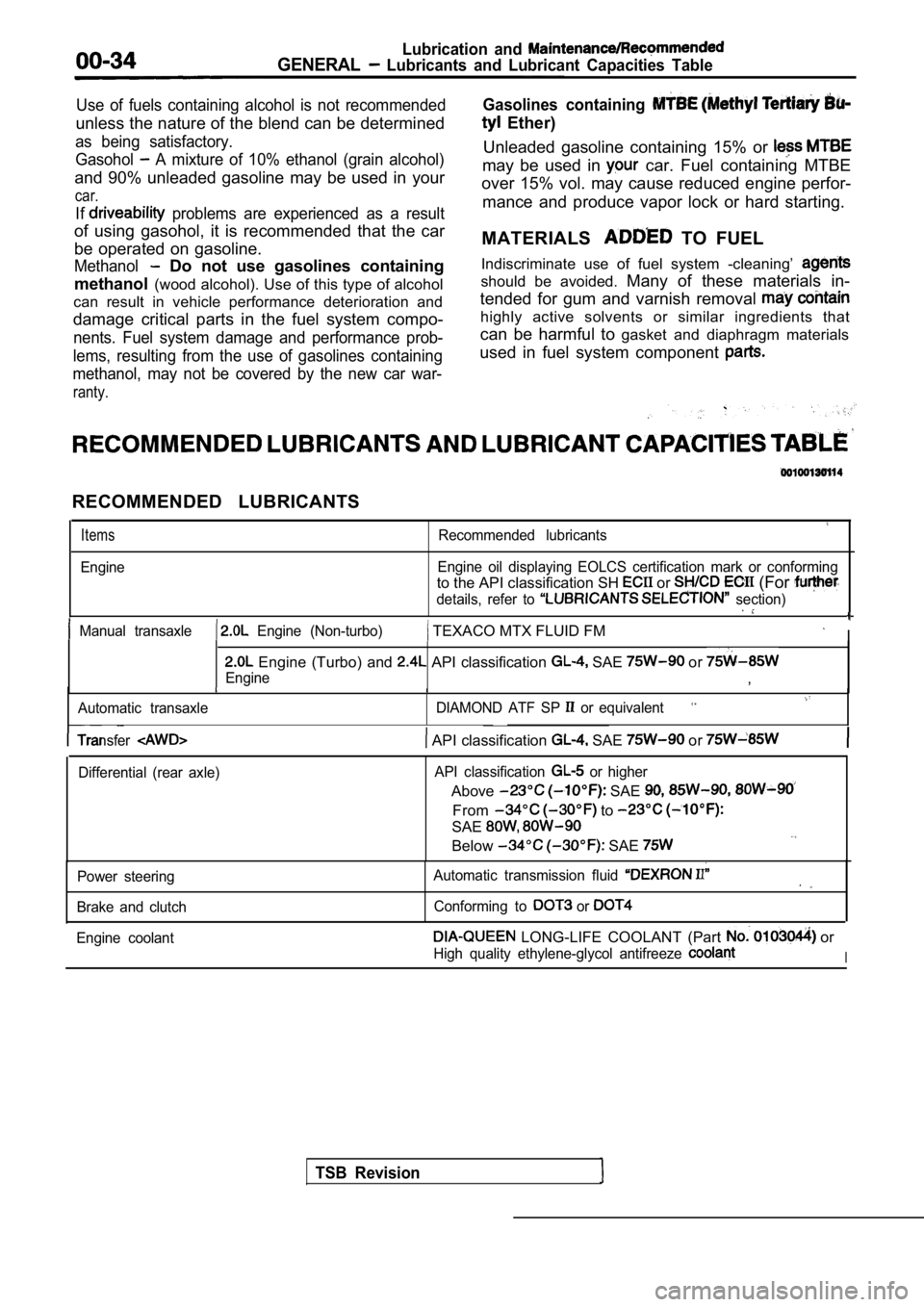
RECOMMENDED LUBRICANTS
Items
Engine
Recommended lubricants
Engine oil displaying EOLCS certification mark or c onforming
to the API classification SH or (For
details, refer to section)
Manual transaxle Engine (Non-turbo) TEXACO MTX FLUID FM I
Engine (Turbo) and API classification SAE or
Engine,
Automatic transaxle DIAMOND ATF SP or equivalent
TSB Revision
Transfer API classification SAE or
Differential (rear axle)API classification or higher
Above SAE
From to
SAE
Below SAE
Power steering
Brake and clutch Automatic transmission fluid
Conforming to or
Engine coolant LONG-LIFE COOLANT (Part or
High quality ethylene-glycol antifreeze I
Page 47 of 2103
GENERAL Maintenance, Service
5. Tighten filler plug to specified torque.
Specified torque:
Engine (Non-turbo)>30 Nm (22
Engine (Turbo) and Engine>
32 Nm (24
12. AUTOMATIC TRANSAXLE FLUID
(Check ‘fluid level)
Engine (Non-turbo)>
1. Position the vehicle on a level surface.
2. Start engine and allow to idle in PARK for at le ast 60
seconds. The warmer the transaxle fluid, the more
accurate the reading.
3.While sitting in driver seat, apply brakes and plac e gear
selector in each position. Return gear selector to PARK.
4. Raise hood and remove transaxle fluid level indi cator
(dipstick) and wipe clean with a suitable shop towe l.
5.
dipstick and verify it is seated in fill tube.
Caution
Do not overfill automatic transaxle, leakage or dam age
can result.
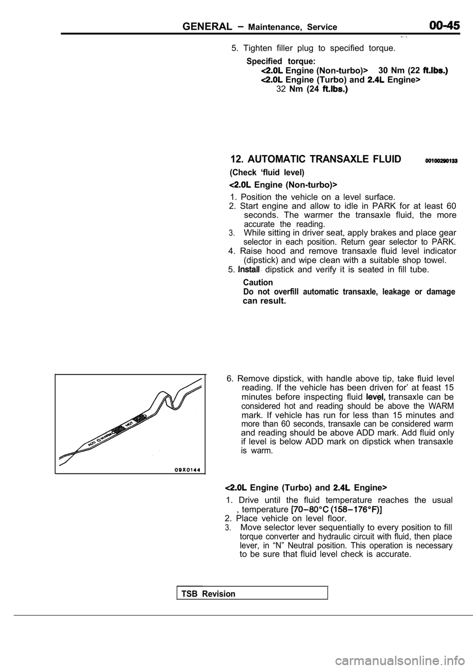
6. Remove dipstick, with handle above tip, take flu id level
reading. If the vehicle has been driven for’ at fea st 15
minutes before inspecting fluid
transaxle can be
considered hot and reading should be above the WARM
mark. If vehicle has run for less than 15 minutes a nd
more than 60 seconds, transaxle can be considered w arm
and reading should be above ADD mark. Add fluid onl y
if level is below ADD mark on dipstick when transax le
is warm.
Engine (Turbo) and Engine>
1. Drive until the fluid temperature reaches the us ual
, temperature
2. Place vehicle on level floor.
3.Move selector lever sequentially to every position to fill
torque converter and hydraulic circuit with fluid, then place
lever, in “N” Neutral position. This operation is n ecessary
to be sure that fluid level check is accurate.
TSB Revision
Page 49 of 2103
GENERALMaintenance Service
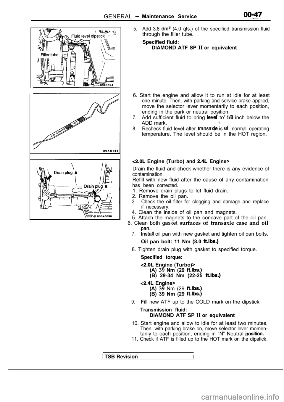
5.Add 3.8 (4.0 qts.) of the specified transmission fluid
through the filler tube.
Specified fluid:DIAMOND ATF SP IIor equivalent
6. Start the engine and allow it to run at idle for at least
one minute. Then, with parking and service brake ap plied,
move the selector lever momentarily to each positio n,
ending in the park or neutral position.
7.Add sufficient fluid to bring to’ inch below the
ADD mark.
8.Recheck fluid level after is normal operating
temperature. The level should be in the HOT region.
Engine (Turbo) and Engine>
Drain the fluid and check whether there is any evid ence of
contamination.
Refill with new fluid after the cause of any contam ination
has been corrected.
1. Remove drain plugs to let fluid drain.
2. Remove the oil pan.
3.Check the oil filter for clogging and damage and re place
if necessary.
4. Clean the inside of oil pan and magnets.
5. Attach the magnets to the concave part of the oi l pan.
6. Clean both gasket surfaces of transaxle case and oil
7. oil pan with new gasket and tighten oil pan bolts.
Oil pan bolt: 11 Nm (8.0
8. Tighten drain plug with gasket to specified torq ue.
Specified torque:
Engine (Turbo)>
(A) 39Nm (29
(B) 29-34 Nm (22-25
Engine>
(A) 39Nm (29
(B) 39 Nm (29
9.Fill new ATF up to the COLD mark on the dipstick.
Transmission fluid:
DIAMOND ATF SP IIor equivalent
10. Start engine and allow to idle for at least two minutes.
Then, with parking brake on, move selector lever mo men-
tarily to each position, ending in “N” Neutral
11. Check if ATF is filled up to the HOT mark on the dipstick.
TSB RevisionI
Page 51 of 2103
GENERAL Maintenance
a
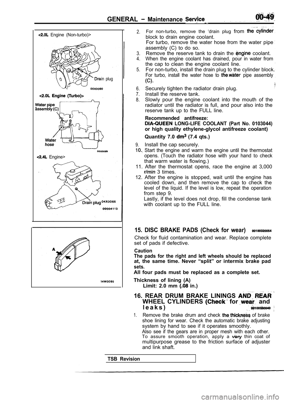
Engine (Non-turbo)>
in plug
Engine>
2.For non-turbo, remove the ‘drain plug from
block to drain engine coolant.
For turbo, remove the water hose from the water pip e
assembly (C) to do so.
3.
4.
5.Remove the reserve tank to drain the coolant.
When the engine coolant has drained, pour in water from
the cap to clean the engine coolant line.
For non-turbo, install the drain plug to the cylind er block.
For turbo, install the water hose to pipe assembly
6.
7.
8.
Securely tighten the radiator drain plug.
Install the reserve tank.
9.
Slowly pour the engine coolant into the mouth of th e
radiator until the radiator is full, and pour also into the
reserve tank up to the FULL line.
Recommended antifreeze:
LONG-LIFE COOLANT (Part No. 0103044)
or high quality ethylene-glycol antifreeze coolant)
Quantity 7.0
(7.4 qts.)
Install the cap securely.
Start the engine and warm the engine until the the rmostat
opens. (Touch the radiator hose with your hand to c heck
that warm water is flowing.)
11. After the thermostat opens, race the engine at 3,000
3 times.
12. After the engine is stopped, wait until the eng ine has
cooled down, and then remove the cap to check the
level of the liquid. If the level is low, repeat th e operation
from step 9.
Lastly, if the level does not drop, fill the conden se tank
with coolant up to the FULL line.
15. DISC BRAKE PADS (Check for wear)
Check for fluid contamination and wear. Replace com plete
set of pads if defective.
Caution
The pads for the right and left wheels should be re placed
at, the same time. Never “split” or intermix brake pad
sets.
All four pads must be replaced as a complete set.
Thickness of lining (A) Limit: 2.0 mm
in.)
16. REAR DRUM BRAKE LININGS
WHEEL CYLINDERS for and
l e a k s )
1.Remove the brake drum and check of brake
shoe lining for wear. Check the automatic brake adj usting
system by hand to see if it operates smoothly.
Also see if the gears are in proper mesh with each other.
To assure smooth operation, apply a thin coat of
multipurpose grease to the friction surface of adju ster
and link shaft.
TSB Revision
Page 52 of 2103
GENERAL Maintenance Service
2.Check the wheel cylinder boots for evidence, a’ brake
fluid leak. Visually check the
boots for tears or
cracks. (A slight amount of fluid on the boot may not
be a leak, but may be preservative assembly.)
Caution
The shoes for the right and left be,
replaced at the same time.
Never split or intermix brake
sets.
All four shoes must be replaced as a set.
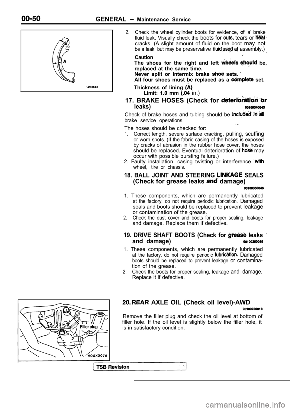
Thickness of lining
Limit: 1.0 mm in.)
17. BRAKE HOSES (Check for
leaks)
Check of brake hoses and tubing should be
brake service operations.
The hoses should be checked for:
1.Correct length, severe surface cracking, pulling, scuffing
or worn spots. (If the fabric casing of the hoses i s exposed
by cracks of abrasion in the rubber hose cover, the hoses
should be replaced. Eventual deterioration of may
occur with possible bursting failure.)
2. Faulty installation, casing twisting or interfer ence
wheel,’ tire or chassis.
18. BALL JOINT AND STEERING SEALS
(Check for grease leaks damage)
1. These components, which are permanently lubricat ed
at the factory, do not require periodic lubrication. Damaged
seals and boots should be replaced to prevent leakage
or contamination of the grease.
2.Check the dust cover and boots for proper sealing, leakage
and damage. Replace them if defective.
19. DRIVE SHAFT BOOTS (Check for leaks
and damage)
1. These components, which are permanently lubricat ed
at the factory, do not require periodic Damaged
boots should be replaced to prevent leakage or contamina-
tion of the grease.
2.Check the boots for proper sealing, leakage and damage.
Replace it if defective.
AXLE OIL (Check oil level)-AWD
Remove the filler plug and check the oil level at bottom of
filler hole. If the oil level is slightly below the filler hole, it
is in satisfactory condition.
Page 833 of 2103
CLUTCH Service Specifications/Lubricants
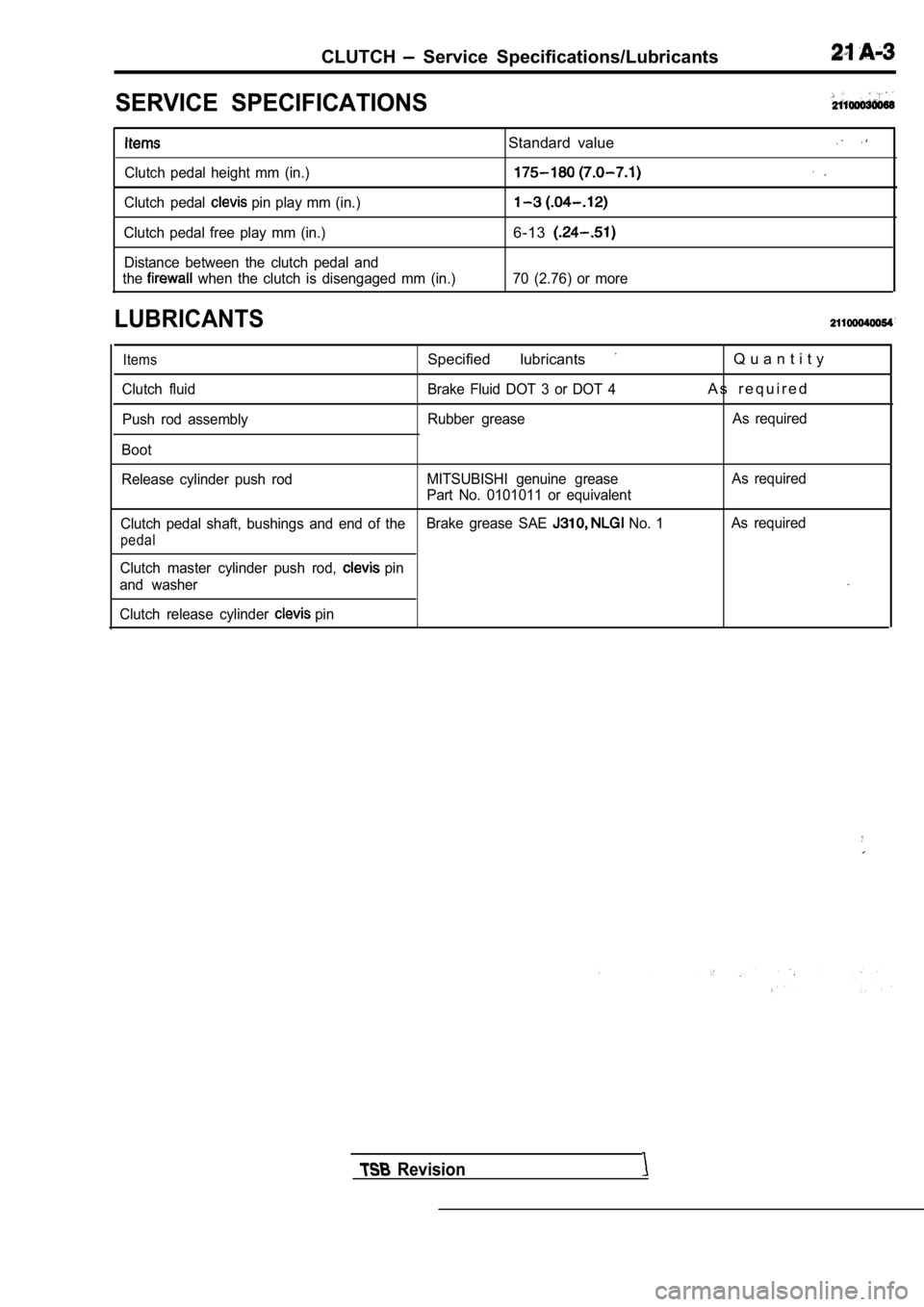
SERVICE SPECIFICATIONS
Clutch pedal height mm (in.)
Clutch pedal
pin play mm (in.)
Clutch pedal free play mm (in.) Distance between the clutch pedal and
the
when the clutch is disengaged mm (in.)
LUBRICANTS
Standard value
6-13
70 (2.76) or more
Items
Clutch fluid
Push rod assembly
Boot
Specified lubricants
Brake Fluid DOT 3 or DOT 4
Rubber grease
Q u a n t i t y
A s r e q u i r e d
As required
Release cylinder push rod MITSUBISHI genuine grease
Part No. 0101011 or equivalentAs required
Clutch pedal shaft, bushings and end of the Brake grease SAE
No. 1As required
pedal
Clutch master cylinder push rod, pin
and washer
Clutch release cylinder
pin
Revision
Page 837 of 2103
CLUTCH On-vehicle Service
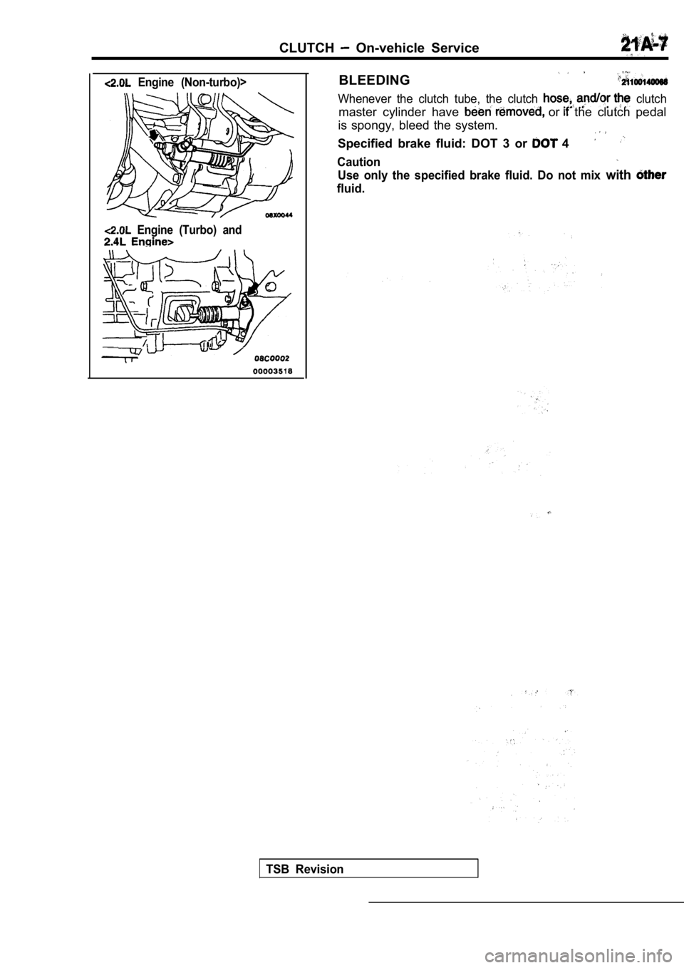
Engine (Non-turbo)>
Engine (Turbo) and
BLEEDING
Whenever the clutch tube, the clutch clutch
master cylinder have or the clutch pedal
is spongy, bleed the system.
Specified brake fluid: DOT 3 or 4
Caution
Use only the specified brake fluid. Do not mix with
fluid.
TSB Revision
Page 843 of 2103
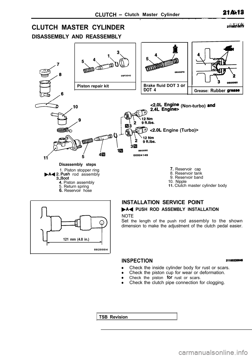
CLUTCHClutch Master Cylinder. . .
CLUTCH MASTER CYLINDER
DISASSEMBLY AND REASSEMBLY
Piston repair kitBrake fluid DOT 3 or
DOT 4Grease:Rubber
(Non-turbo)
Engine (Turbo)>
Disassembly steps
1. Piston stopper ring rod assembly
Piston assembly
5. Return spring
6.Reservoir hose
121 mm (4.8 in.)
7.Reservoir cap8. Reservoir tank
9. Reservoir band
10. Nipple11. Clutch master cylinder body
INSTALLATION SERVICE POINT
PUSH ROD ASSEMBLY INSTALLATION
NOTE
Set the length of the push rod assembly to the shown
dimension to make the adjustment of the clutch peda l easier.
0 8 2 0 0 0 4
INSPECTION
lCheck the inside cylinder body for rust or scars.
lCheck the piston cup for wear or deformation.
lCheck the piston rust or scars.
lCheck the clutch pipe connection for clogging.
TSB Revision
Page 847 of 2103
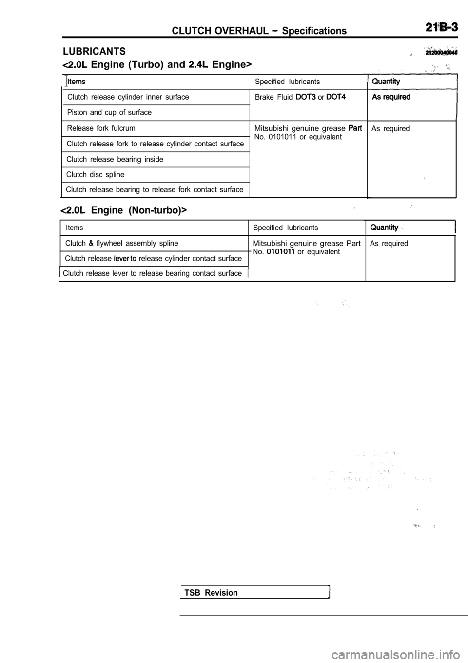
CLUTCH OVERHAUL Specifications
LUBRICANTS
Engine (Turbo) and Engine>
ISpecified lubricants
Clutch release cylinder inner surface
Piston and cup of surface
Release fork fulcrum Brake Fluid or
Mitsubishi genuine grease
No. 0101011 or equivalent
Clutch release fork to release cylinder contact sur face
Clutch release bearing inside
Clutch disc spline
Clutch release bearing to release fork contact surf ace
Engine (Non-turbo)>
Items
Clutch flywheel assembly splineSpecified lubricantsMitsubishi genuine grease Part
No. or equivalent
Clutch release release cylinder contact surface
Clutch release lever to release bearing contact su rface
As required
As required
TSB Revision