brake rotor MITSUBISHI SPYDER 1990 Service Repair Manual
[x] Cancel search | Manufacturer: MITSUBISHI, Model Year: 1990, Model line: SPYDER, Model: MITSUBISHI SPYDER 1990Pages: 2103, PDF Size: 68.98 MB
Page 1555 of 2103
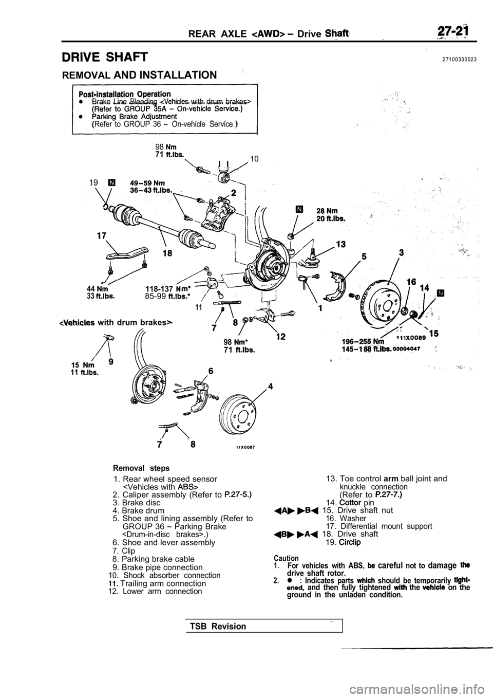
REAR AXLE Drive
2 7 1 0 0 3 3 0 0 2 3
REMOVAL AND INSTALLATION
Brake Line Bleeding with drum brakes>
(Refer to GROUP 36
On-vehicle Service.)
9871
I I10
,19
44118-1373385-99
11
with drum brakes>
11
9871. .,
Removal steps
1. Rear wheel speed sensor
4. Brake drum
5. Shoe and lining assembly (Refer to
GROUP 36
Parking Brake
7. Clip8. Parking brake cable
9. Brake pipe connection
10. Shock absorber connection Trailing arm connection12. Lower arm connection
13. Toe control armball joint andknuckle connection(Refer to 14. pin 15. Drive shaft nut16. Washer
17. Differential mount support
18. Drive shaft
19.
Caution1.For vehicles with ABS, careful not to damagedrive shaft rotor.2.l : Indicates parts should be temporarily and then fully tightened the on the
ground in the unladen condition.
TSB Revision
Page 1639 of 2103
B R A K E
S Y S T E M
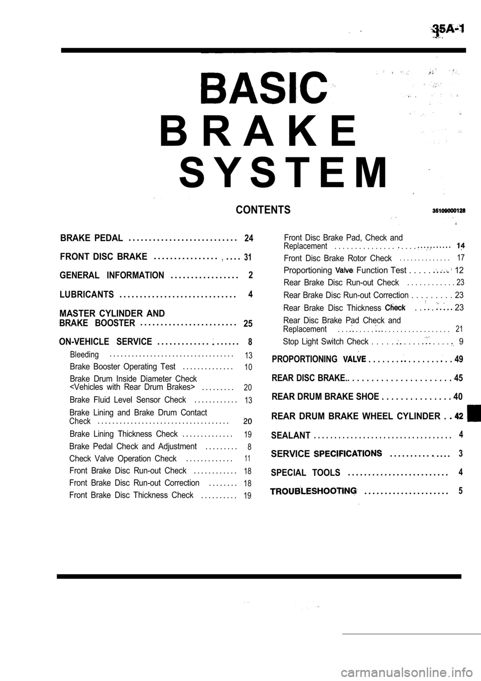
CONTENTS
BRAKE PEDAL. . . . . . . . . . . . . . . . . . . . . . . . . . .24
FRONT DISC BRAKE. . . . . . . . . . . . . . . .,. . . .31
GENERAL INFORMATION. . . . . . . . . . . . . . . . .2
LUBRICANTS. . . . . . . . . . . . . . . . . . . . . . . . . . . . .4
MASTER CYLINDER AND
BRAKE BOOSTER. . . . . . . . . . . . . . . . . . . . . . . .25
ON-VEHICLE SERVICE
. . . . . . . . . . . . .. . . . . .8
Bleeding. . . . . . . . . . . . . . . . . . . . . . . . . . . . . . . . . .13
Brake Booster Operating Test. . . . . . . . . . . . . .10
Brake Drum Inside Diameter Check
. . . . . . . . .20
Brake Fluid Level Sensor Check. . . . . . . . . . . .13
Brake Lining and Brake Drum Contact
Check. . . . . . . . . . . . . . . . . . . . . . . . . . . . . . . . . . . .
Brake Lining Thickness Check. . . . . . . . . . . . . .19
Brake Pedal Check and Adjustment. . . . . . . . .8
Check Valve Operation Check. . . . . . . . . . . . .11
Front Brake Disc Run-out Check. . . . . . . . . . . .18
Front Brake Disc Run-out Correction. . . . . . . .18
Front Brake Disc Thickness Check. . . . . . . . . .19
Front Disc Brake Pad, Check and
Replacement. . . . . . . . . . . . . . . . . . .
Front Disc Brake Rotor Check. . . . . . . . . . . . . .17
Proportioning Function Test . . . . . 12
Rear Brake Disc Run-out Check. . . . . . . . . . . . 23
Rear Brake Disc Run-out Correction . . . . . . . . . 23
Rear Brake Disc Thickness
. . . 23
Rear Disc Brake Pad Check and
Replacement. . . . . . . . . . . . . . . . . . . . . . . . . 21
Stop Light Switch Check . . . . . . . . . . . . . 9
PROPORTIONING . . . . . . . . . . . . . . . . 49
REAR DISC BRAKE.. . . . . . . . . . . . . . . . . . . . . . 45
REAR DRUM BRAKE SHOE . . . . . . . . . . . . . . . 40
REAR DRUM BRAKE WHEEL CYLINDER .
SEALANT. . . . . . . . . . . . . . . . . . . . . . . . . . . . . . . . . .4
SERVICE. . . . . . . . . .. . . .3
SPECIAL TOOLS. . . . . . . . . . . . . . . . . . . . . . . . .4
. . . . . . . . . . . . . . . . . . . . .5
Page 1643 of 2103
BASIC BRAKE SYSTEM Troubleshooting
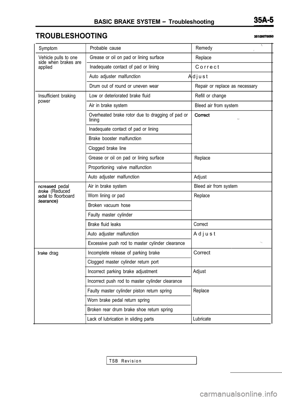
TROUBLESHOOTING
SymptomProbable cause
Remedy
Vehicle pulls to oneGrease or oil on pad or lining surface
Replace
side when brakes are
applied Inadequate contact of pad or lining
C o r r e c t
Auto adjuster malfunctionA d j u s t
Drum out of round or uneven wear Repair or replace a
s necessary
Insufficient braking Low or deteriorated brake fluid Refill or change
power Air in brake system Bleed air from system
Overheated brake rotor due to dragging of pad or
lining
Inadequate contact of pad or lining
Brake booster malfunction
Clogged brake line
pedal
(Reduced
to floorboard
drag
Grease or oil on pad or lining surface
Proportioning valve malfunction
Auto adjuster malfunction
Air in brake system
Worn lining or pad
Broken vacuum hose
Faulty master cylinder
Brake fluid leaks
Auto adjuster malfunction Excessive push rod to master cylinder clearance
Incomplete release of parking brake
Clogged master cylinder return port
Incorrect parking brake adjustment
Incorrect push rod to master cylinder clearance
Faulty master cylinder piston return spring
Worn brake pedal return spring
Broken rear drum brake shoe return spring Replace
Adjust Bleed air from system
Replace
Correct
A d j u s t
Correct
Adjust Replace
Lack of lubrication in sliding parts Lubricate
T S B R e v i s i o n
Page 1655 of 2103
B R A K E S Y S T E M 7 .
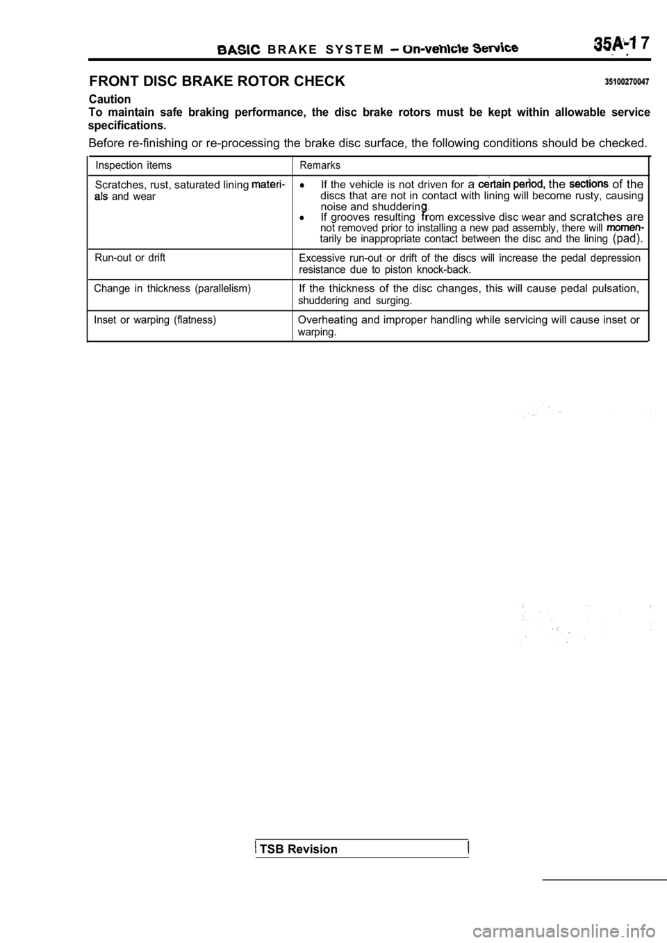
FRONT DISC BRAKE ROTOR CHECK
35100270047
Caution
To maintain safe braking performance, the disc brak e rotors must be kept within allowable service
specifications.
Before re-finishing or re-processing the brake disc surface, the following conditions should be checke d.
Inspection itemsRemarks
Scratches, rust, saturated lining lIf the vehicle is not driven for a the of the
and weardiscs that are not in contact with lining will beco me rusty, causing
noise and shudderin.lIf grooves resultingrom excessive disc wear and scratches arenot removed prior to installing a new pad assembly, there will tarily be inappropriate contact between the disc and the lining (pad).
Run-out or drift
Excessive run-out or drift of the discs will increa se the pedal depression
resistance due to piston knock-back.
Change in thickness (parallelism)
If the thickness of the disc changes, this will cau se pedal pulsation,
shuddering and surging.
Inset or warping (flatness)
Overheating and improper handling while servicing w ill cause inset or
warping.
TSB Revision
Page 1656 of 2103
BASIC BRAKE SYSTEM On-vehicle Service
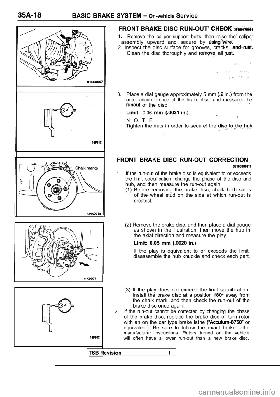
FRONT DISC RUN-OUT’
Remove the caliper support bolts, then raise the’ c aliper
assembly upward and secure by
2. Inspect the disc surface for grooves, cracks,
Clean the disc thoroughly and all
,
3.Place a dial gauge approximately 5 mm in.) from the
outer circumference of the brake disc, and measure- the.
of the disc
Limit:0.06mm in.)
N O T E
Tighten the nuts in order to secure! the
FRONT BRAKE DISC RUN-OUT CORRECTION
1.If the run-out of the brake disc is equivalent to o r exceeds
the limit specification, change the phase of the di sc and
hub, and then measure the run-out again.
(1) Before removing the brake disc, chalk both side s
of the wheel stud on the side at which run-out is
greatest.
(2) Remove the brake disc, and then place a dial ga uge
as shown in the illustration; then move the hub in
the axial direction and measure the play.
Limit: 0.05 mm
in.)
If the play is equivalent to or exceeds the limit,
disassemble the hub knuckle and check each part.
2.
(3) If the play does not exceed the limit specifica tion,
install the brake disc at a position
away from
the chalk mark, and then check the run-out of the
brake disc once again.
If the run-out cannot be corrected by changing the phase
of the brake disc, replace the brake disc or turn rotor
with an on the car type brake lathe
or
equivalent). Be sure to follow the exact brake lath e
manufacturer instructions. Rotors turned on the veh icle
will often have a lower run-out than a new brake di sc.
TSB RevisionI
Page 1657 of 2103
BASIC On-vehicle Service
BRAKE DISC THICKNESS CHECK
35100160122
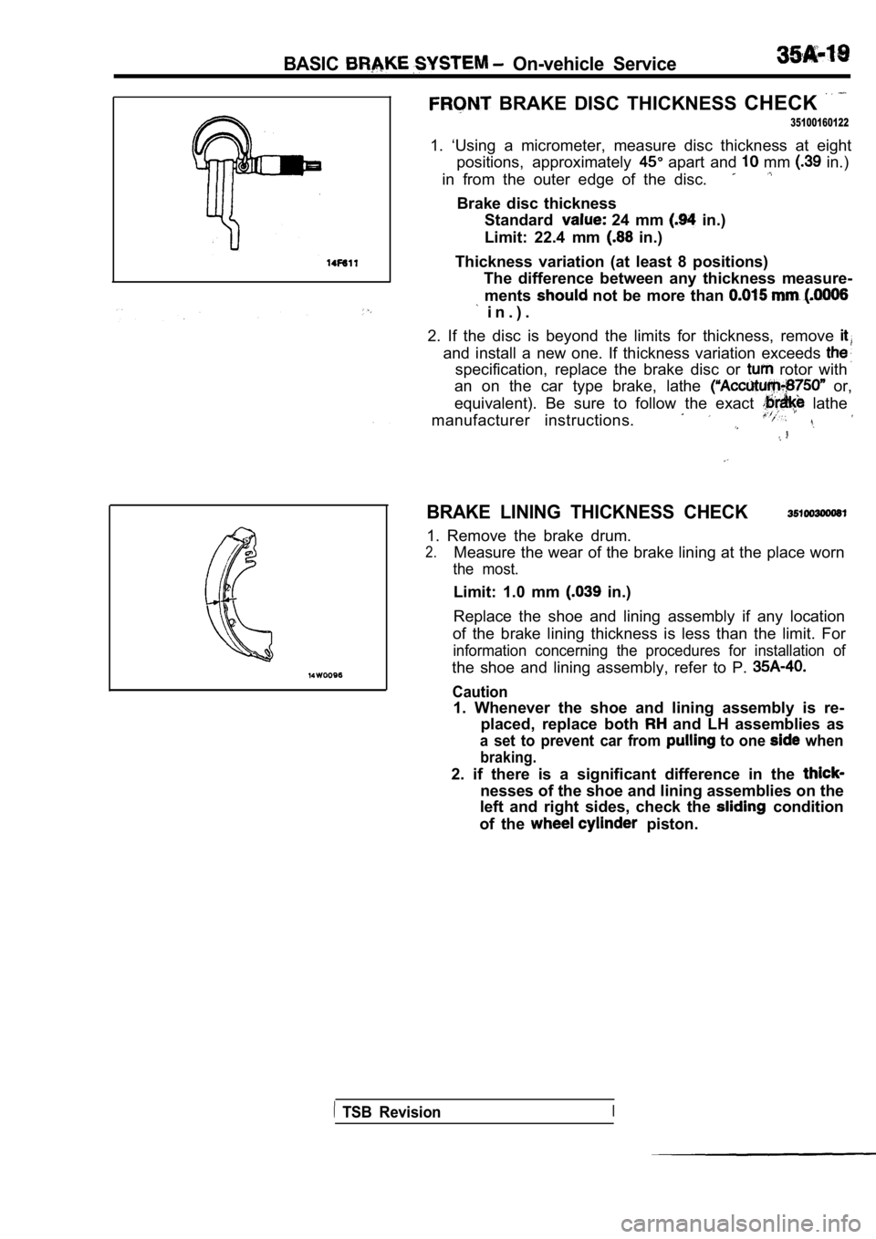
1. ‘Using a micrometer, measure disc thickness at e ight
positions, approximately
apart and mm in.)
in from the outer edge of the disc.
Brake disc thickness Standard
24 mm in.)
Limit: 22.4 mm
in.)
Thickness variation (at least 8 positions) The difference between any thickness measure-
ments
not be more than
i n . ) .
2. If the disc is beyond the limits for thickness, remove
and install a new one. If thickness variation excee ds
specification, replace the brake disc or rotor with
an on the car type brake, lathe
or,
equivalent). Be sure to follow the exact
lathe
manufacturer instructions.
BRAKE LINING THICKNESS CHECK
1. Remove the brake drum.
2.Measure the wear of the brake lining at the place w orn
the most.
Limit: 1.0 mm in.)
Replace the shoe and lining assembly if any locatio n
of the brake lining thickness is less than the limi t. For
information concerning the procedures for installat ion of
the shoe and lining assembly, refer to P.
Caution
1. Whenever the shoe and lining assembly is re-
placed, replace both
and LH assemblies as
a set to prevent car from to one when
braking.
2. if there is a significant difference in the
nesses of the shoe and lining assemblies on the
left and right sides, check the
condition
of the
piston.
TSB RevisionI
Page 1661 of 2103
BASIC BRAKE SYSTEM On-vehicle Service
REAR BRAKE DISC THICKNESS CHECK
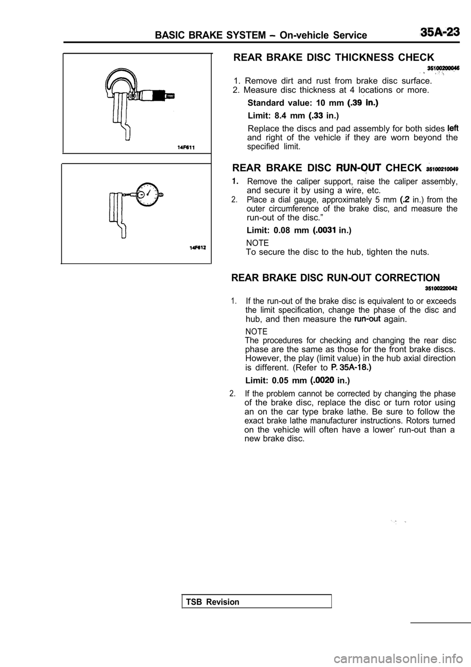
1. Remove dirt and rust from brake disc surface.
2. Measure disc thickness at 4 locations or more.
Standard value: 10 mm
Limit: 8.4 mm in.)
Replace the discs and pad assembly for both sides
and right of the vehicle if they are worn beyond th e
specified limit.
REAR BRAKE DISC CHECK
Remove the caliper support, raise the caliper assem bly,
and secure it by using a wire, etc.
2.Place a dial gauge, approximately 5 mm in.) from the
outer circumference of the brake disc, and measure the
run-out of the disc.”
Limit: 0.08 mm
in.)
NOTE
To secure the disc to the hub, tighten the nuts.
REAR BRAKE DISC RUN-OUT CORRECTION
1.If the run-out of the brake disc is equivalent to o r exceeds
the limit specification, change the phase of the di sc and
hub, and then measure the again.
NOTE
The procedures for checking and changing the rear d isc
phase are the same as those for the front brake discs.
However, the play (limit value) in the hub axial di rection
is different. (Refer to
Limit: 0.05 mm in.)
2.If the problem cannot be corrected by changing the phase
of the brake disc, replace the disc or turn rotor using
an on the car type brake lathe. Be sure to follow t he
exact brake lathe manufacturer instructions. Rotors turned
on the vehicle will often have a lower’ run-out tha n a
new brake disc.
TSB Revision
Page 1689 of 2103
CONTENTS
ABS-ECU. . . . . . . . . . . . . . . . . . . . . . . . . . . . . . . . .41 VALVE. . . . . . . . . . . . . . . . .
GENERAL INFORMATION. . . . . . . . . . . . . . . . .2SERVICE SPECIFICATIONS.. . . . . . . . . . . . . .3
HYDRAULIC UNIT . . . . . . . . . . . . . . . . . . . . . . . . .36SPECIAL TOOLS . . . . . . . . . . . . . . . . . . . . . . . . . .3
MASTER CYLINDER ANDTROUBLESHOOTING.. . . . . . . . . .. . . . . . . . .4
BRAKE BOOSTER. . . . . . . . . . . . . . . . . . . . . . . . .32..
W H E E L S P E E D .. . . .... . . . . . . . . . . . .38
ON-VEHICLE SERVICE24.... . . . . . . . . . . . . . . . . . . .
ABS Operation Check . . . . . . . . . . . . . . . . . . . . . . .
24
Bleeding
. . . . .. . . . . . . . . . . . . . . . . . . . . . . . . . . .24
Refer to GROUP for the following items.
BRAKE PEDAL
FRONT DISC BRAKE
LUBRICANTS
REAR DISC BRAKE
REAR DRUM BRAKE SHOE
REAR DRUM BRAKE WHEEL CYLINDER
ON-VEHICLE SERVICE
Brake Booster Operating Test
Brake Drum inside Diameter Check
Brake Fluid Level Sensor Check
Brake Lining and Brake Drum Contact Check
Brake Lining Thickness Check
Brake Pedal Check and Adjustment
Check Valve Operation Check
Front Brake Disc Run-out Check
Front Brake Disc Run-out Correction
Front Brake Disc Thickness Check
Front Disc Brake Pad Check and Replacement
Front Disc Brake Rotor Check
Proportioning Valve Function Test
Rear Brake Disc Run-out
Rear Brake Disc Run-out
Rear Brake Disc Thickness
Rear Disc Brake Pad and Replacement
S t o p L i g h t S w i t c h
Page 1726 of 2103
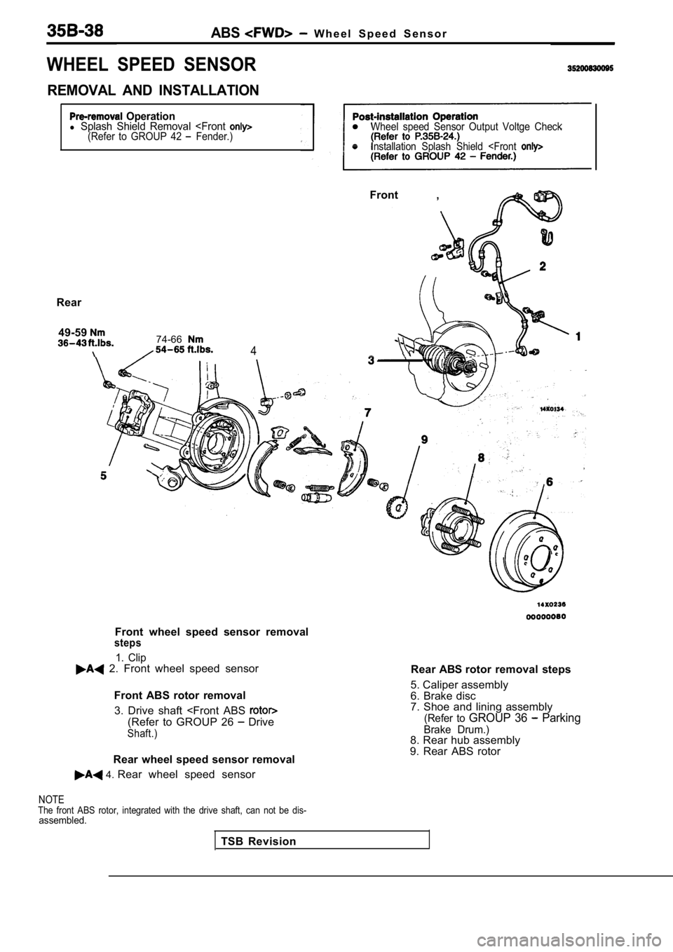
ABS W h e e l S p e e d S e n s o r
WHEEL SPEED SENSOR
REMOVAL AND INSTALLATION
Operationl Splash Shield Removal
Rear 49-59
74-66
4
Front wheel speed sensor removalsteps
1. Clip 2. Front wheel speed sensor Front ABS rotor removal3. Drive shaft
Shaft.)
Rear wheel speed sensor removal
4. Rear wheel speed sensor
Rear ABS rotor removal steps
5. Caliper assembly
6. Brake disc
7. Shoe and lining assembly
(Refer to GROUP 36 Parking
Brake Drum.)8. Rear hub assembly
9. Rear ABS rotor
NOTEThe front ABS rotor, integrated with the drive shaf t, can not be dis-assembled.
TSB Revision
Page 2093 of 2103
ALPHABETICAL
A
ABS OPERATIONCheck. . . . . . . . . . . . . . . . . . . . . . . . . . . . . . . . . . .
. . . . . . . . . . . . . . . . . . . . . . . . . . . . . . . . . . .
ABS-ECU. . . . . . . . . . . . . . . . . . . . . . . . . . . . . . . . . . . . . . . . .
. . . . . . . . . . . . . . . . . . . . . . . . . . . . . . . . . . . . . . . . .
ACCELERATOR CABLE. . . . . . . . . . . . . . . . . . . . . . . . . . . . . . . .Adjustment. . . . . . . . . . . . . . . . . . . . . . . . . . . . . . . . . . . . . . . . .
Check. . . . . . . . . . . . . . . . . . . . . . . . . . . . . . . . . . . . . . . . . . . . .ACCELERATOR PEDAL. . . . . . . . . . . . . . . . . . . . . . . . . . . . . . . .
ADAPTER, Transfer Case . . . . . . . . . . . . . . . . . .
AERO PARTS. . . . . . . . . . . . . . . . . . . . . . . . . . . . . . . . . . . . . . . .
AIR BAG CONTROL UNIT (SRS-ECU), SRS. . . . . . . . . . .AIR BAG MODULES. . . . . . . . . . . . . . . . . . . . . . . . . . . . . . . . .
Deployed Disposal Procedures. . . . . . . . . . . . . . . . . . . . .
Disposal Procedures. . . . . . . . . . . . . . . . . . . . . . . . . . . . .
Disposal. . . . . . . . . . . . . . . . . . . . . . . . . . . . .
AIR CLEANER ELEMENT, Maintenance. . . . . . . . . . . . . . . . . .AIR CONDITIONING SWITCH
ENGINE (NON-TURBO)>. . . . . . . . . . . . . . ENGINE (TURBO) AND .AIR COOLER, charge. . . . . . . . . . . . . . . . . . . . . . . . . . . . . . . . . . .
AIR FILTER. . . . . . . . . . . . . . . . . . . . . . . . . . . . . . . . . . . . . . . . . .
ALIGNMENT
Front Wheel, Check and Adjustment. . . . . . . . . . . . . . . . .
Wheel, Rear, Check and Adjustment. . . . . . . . . . . . . . . . . . .AMPLIFIER. . . . . . . . . . . . . . . . . . . . . . . . . . . . . . . . . . . . . . . . . .
GEAR AND TRANSFER DRIVE GEAR SET
. . . . . . . . . . . . . . . . . . . . . . . . . . . . . . . .
. . . . . . . . . . . . . . . . . . . . . . . . . . . . . . . . . . . . . . . .
ANTENNA.
ARM Compression, Lower
. . . . . . . . . . . . . . . . . . . . . . . . . . . . . . .Lateral, Lower. . . . . . . . . . . . . . . . . . . . . . . . . . . . . . . . . . .
Lower. . . . . . . . . . . . . . . . . . . . . . . . . . . . . . . . . . . . . . . . . . . . .
Toe Control. . . . . . . . . . . . . . . . . . . . . . . . . . . . . . . . . . . . . . . .
Trailing. . . . . . . . . . . . . . . . . . . . . . . . . . . . . . . . . . . . . . . . . . . .
Upper
Suspension>. . . . . . . . . . . . . . . . . . . . . . . . . . .ARMS, Rocker . . . . . . . . . . . . . . . . . . . . . . . . . . .11AUTO-CRUISE CONTROL. . . . . . . . . . . . . . . . . . . . . . . . . . . . .
AUTO-CRUISE CONTROL CABLE, Check andAdjustment. . . . . . . . . . . . . . . . . . . . . . . . . . . . . . . . . . . . . . . . . . .
AUTO-CRUISE CONTROL COMPONENT, Check. . . . . . . . .AUTO-CRUISE CONTROL SYSTEM, Operation Check. . . .AUTOMATIC TRANSAXLE FLUID, Maintenance. . . . . . . . . .AUTOMATIC TRANSAXLE CONTROL COMPONENTCheck
ENGINE (NON-TURBO)>.. . . . . . . . . . . .Layout ENGINE (NON-TURBO)>. . . . . . . . . . . .AUTOMATIC TRANSAXLE KEY INTERLOCK AND SHIFT LOCKMECHANISMS
ENGINE (NON-TURBO)>. . . . . . . . . . . . . . . . . . .
ENGINE (TURBO) AND ENGINE>.. . . . . . .AXLE
Rear, Total Backlash Check. . . . . . . . . . . . . . . . . . . . . . . . . .
AXLE OIL
Rear, Maintenance
. . . . . . . . . . . . . . . . . . . . . . . . . . . . . . . . .
BACK-UP LIGHT. . . . . . . . . . . . . . . . . . . . . . . . . . . . . . . . . . . . .BALL JOINT, Tie Rod End, Breakaway Torque Check. . . . .BALL JOINT SEALS, Maintenance. . . . . . . . . . . . . . . . . . . . . .
BARStabilizer Suspension>. . . . . . . . . . . . . . . . . . . . .
Suspension>. . . . . . . . . . . . . . . . . . . . . . . .
BASIC IDLE SPEED, Adjustment ENGINE (TURBO)
AND ENGINE>. . . . . . . . . . . . . . . . . . . . . . . . . . . . . . . .
BATTERY
Charging
. . . . . . . . . . . . . . . . . . . . . . . . . . . . . . . . . . . . . . . . . .
Check. . . . . . . . . . . . . . . . . . . . . . . . . . . . . . . . . . . . . . . . . . ..Testing Procedure. . . . . . . . . . . . . . . . . . . . . . . . . . . . .. . .
BELT
Compressor, Adjustment. . . . . . . . . . . . . . . . . . . . . . . . .
(For Generator), Maintenance. . . . . . . . . . . .. . . . . (For Power steering pump), Maintenance. . . . . . . . . (For Water pump), Maintenance. . . . . . . . .. .. . .Timing. . . . . . . . . . . . . . . . . . . .
. . . . . . . . . . . . . . . . . . . . . . . . . . .
Timing. . . . . . . . . . . . . . . . . . . . . . . . . . . . .
. . . . . . . . . . . . . . . . . . . . . ... . . . . . . . .
. . . .Timing, Maintenance. . . . . . . . . . . . . . . . . . . . . . . . . . . . . . . .
BLEEDING
ABS. . . . . . . . . . . . . . . . . . . . . . . . . . . . . . . . . . . . . . . . . . . .
Basic Brakes. . . . . . . . . . . . . . . . . . . . . . . . . . . . . . . . . . . .
Clutch. . . . . . . . . . . . . . . . . . . . . . . . . . . . . . . . . . .. . . . . . .. . . . . . . . . . . . . . . . . . . . . . . . . . . . . . . . . . . . . . . . . .
BLOWER. . . . . . . . . . . . . . . . . . . . . . . . . . . . . . . . . . . . . . . . . . . .
BOLTHub, Replacement . . . . . . . . . . . . . . . . . . .. . . . .
. . . . . . . . . . . . . . . . . . . . . .
. . . . . . . . . . . . . . . . . . . . . . 2 7 4 1
BOOSTER
Brake. . . . . . . . . . . . . . . . . . . . . . . . . . . . . . . . . . . .
. . . . . . . . . . . . . . . . . . . . . . . . . . . . .
Brake, Operating Test. . . . . . . . . . . . . . . . . . . . . . . . . . . . . O-IBOOTS, Shaft, Maintenance. . . . . . . . . . . . . . . . . . . . . . .
BRACKET. . . . . . . . . . . . . . . . . . . . . . . . . . . . . .
BRAKE
. . . . . . . . . . . . . . . . . . . . . . . . . . . . . . . . . . . . . .
Disc, Rear. . . . . . . . . . . . . . . . . . . . . . . . . . . . . . . . . . . . . . .
Low-reverse. . . . . . . . . .. . . . . . . .. . . . . . . . . . . . . . . . . . . . . . . . . . . .
BRAKE BOOSTER
. . . . . . . . . . . . . . . . . . . . . . . . . . . . . . . . . . . . . . . . . .
Test. . . . . . . . . . . . . . . . . . . . . . . . . . . . . . . . . . . .
BRAKE DISC
Front, Run-out Check. . . . . . . . . . . . . . . . . . . . . . . . . .. Run-out Correction. . . . . . . . . . . . . . . . . . . . . . . . . .
Front, Thickness Check. . . . . . . . . . . . . . . . . . . . . . . . . . .
Rear, Run-out Check.. . . . . . . . . . . . . . . . . . . . . . . . . . . . .
Rear, Run-out Correction. . . . . . . . . . . . . . . . . . . . . . . . . .
Rear, Thickness Check. . . . . . . . . . . . . . . . . . . . . . . . . . . .
BRAKE DRUM
Inside Diameter Check with Rear Drum . . . . . . . . . . . . . . . . . . . . . . . . . . . . . . . . . . . . . . . . . . . . . . . . .
BRAKE FLUID LEVEL SENSOR, Check. . . . . . . . . . . . . . . .
BRAKE HOSES, Maintenance. . . . . . . . . . . . . . . . . . . . . . . . . .
BRAKE LINING
Thickness. . . . . . . . . . . . . . . . . . . . . . . . . . . . . . . . . .
BRAKE PAD
Disc, Front, Check and Replacement
. . . . . . . . . . . . . . . .Disc, Rear, Check and Replacement. . . . . . . . . . . . . . . .
BRAKE PEDAL. . . . . . . . . . . . . . . . . . . . . . . . . . . . . . . . . . . . .
Check and Adjustment. . . . . . . . . . . . . . . . . . . .. . . . . . .BRAKE ROTOR, Disc, Front, Check. . . . . . . . . . . . . . . . .BREAKAWAY TORQUE, Rod End Ball Joint, . . .BUMPERFront. . . . . . . . . . . . . . . . . . . . . . . . . . . . . . . . . . . . . . . . . . . . . . .Rear. . . . . . . . . . . . . . . . . . . . . . . . . . . . . . . . . . . . . . . ......