check engine light MITSUBISHI SPYDER 1990 Service Repair Manual
[x] Cancel search | Manufacturer: MITSUBISHI, Model Year: 1990, Model line: SPYDER, Model: MITSUBISHI SPYDER 1990Pages: 2103, PDF Size: 68.98 MB
Page 23 of 2103
GENERAL Precautions before Service . .
Caution
1.Before connecting or disconnecting the negative
be sure to turn off the ignition and
the lighting switch.
(if this is not done, the possibility semi-
conductor parts being damaged.)
2.After completion of the work steps [when the bat-
tery’s negative terminal is connected], warm
up the engine and allow it for approximately
five minutes under the conditions be-
low, in order to stabilize the engine condi-
tions, and then check to be sure that idling’ is
satisfactory.
Engine temperature:
Lights, electric fans, accessories: OFF
Transaxle: Neutral position
(A/T models: “N” or “P”)
Steering
neutral (center) position
mm (in.)
Scan tool
ROM pack
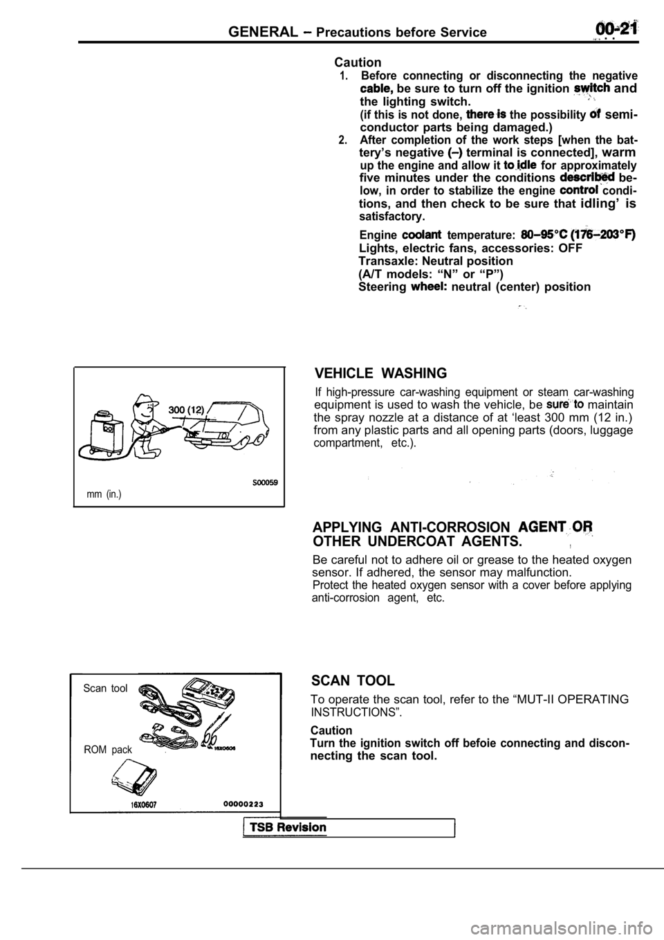
VEHICLE WASHING
If high-pressure car-washing equipment or steam car -washing
equipment is used to wash the vehicle, be maintain
the spray nozzle at a distance of at ‘least 300 mm (12 in.)
from any plastic parts and all opening parts (doors , luggage
compartment, etc.).
APPLYING ANTI-CORROSION
OTHER UNDERCOAT AGENTS.,
Be careful not to adhere oil or grease to the heate d oxygen
sensor. If adhered, the sensor may malfunction.
Protect the heated oxygen sensor with a cover befor e applying
anti-corrosion agent, etc.
SCAN TOOL
To operate the scan tool, refer to the “MUT-II OPER ATING
INSTRUCTIONS”.
Caution
Turn the ignition switch off befoie connecting and discon-
necting the scan tool.
Page 69 of 2103
ENGINE On-vehicle
A/C COMPRESSOR DRIVE BELT TENSION ADJUSTMENT
1. Loosen tension pulley fixing bolt A.
2. Adjust belt tension with adjusting bolt B.
Standard value:
Items
Tension
(Ibs.)
Deflection
When a new belt isWhen a used belt is
installedinstalled
382-411255-333
6.5-7.5
3. Tighten fixing nut A.
Tightening torque: 23-26 Nm
4.Check the belt deflection and readjust if neces-
sary.
Caution
This check should be carried out after turning the
crankshaft one full rotation or more in the forward
direction (to the right).
IGNITION TIMING CHECK
1.Before inspection and adjustment set vehicle in the follow-
ing condition.
lEngine coolant temperature:
lLights, electric cooling fan and all accessories: OFF
lTransaxle: Neutral (P range on vehicles with
2. Turn the ignition switch to OFF and connect the scan
tool to the data link connector.
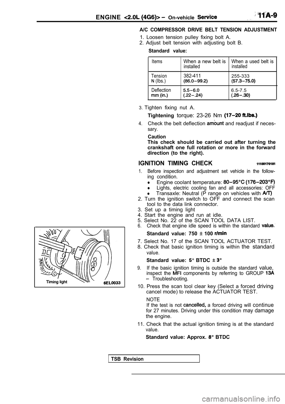
3. Set up a timing light
4. Start the engine and run at idle.
5. Select No. 22 of the SCAN TOOL DATA LIST.
6.Check that engine idle speed is within the standard
Standard value: 750 100
7. Select No. 17 of the SCAN TOOL ACTUATOR TEST.
8. Check that basic ignition timing is within the standard
value.
Standard value: BTDC
9.If the basic ignition timing is outside the standar d value,
inspect the components by referring to GROUP
Troubleshooting.
10. Press the scan tool clear key (Select a forced driving
cancel mode) to release the ACTUATOR TEST.
NOTE
If the test is not
a forced driving will continue
for 27 minutes. Driving under this condition may damage
the engine.
11. Check that the actual ignition timing is at the standard
value.
Standard value: Approx. BTDC
TSB Revision
Page 70 of 2103
ENGINE On-vehicle Service
NOTE
1.Ignition timing is variable within about even under
operating.
2. And it is automatically further advanced by abou t
from BTDC at higher altitudes.
CURB IDLE SPEED CHECK
1. Before inspection and adjustment, set vehicles in the
following condition.
lEngine coolant temperature:
lLights, electric cooling fan and all accessories: OFF
lTransaxle: Neutral (P range on vehicles with
2. Turn the ignition switch to OFF and connect the scan
tool to the data link connector.
3. Select No. 17 of the SCAN TOOL ACTUATOR TEST.
4. Check the basic ignition timing.
Standard
BTDC
5. Run the engine at idle for 2 minutes.
6. Select No. 22 of the SCAN TOOL DATA LIST.
7. Check the curb idle speed.
Standard value: 750
100
NOTE
The idle speed is controlled automatically by the i dle air
control system.
8. If the idle speed is outside the standard value, inspect
the components by referring to GROUP Trou-
bleshooting.
IDLE MIXTURE CHECK .
1.Before inspection, set in following
lEngine coolant temperature:
lLights, electric cooling fan all
lTransaxle: Neutral (P range on
2. Turn the ignition switch to OFF and, connect the scan
tool to the data link ,
3. Select No. 17 of the SCAN TOOL
4.Check that the basic ignition
value.
Standard value: BTDC
5. Run the engine 2,500 for 2 minutes.
6. Set the CO, HC tester.
7. Check the CO contents and the HC contents, at id le.
Standard value: CO contents: 0.5% or less
HC contents: 100 rpm or less
Revision
Page 71 of 2103
ENGINE On-vehicle
8. If the standard value is exceeded, check the following
items:
l Diagnostic output
l Closed-loop control (When the closed-loop control
is carried out normally, the output signal of the h eated
oxygen sensor repeats between and
,000 at idle.)
l Fuel pressure
I n j e c t o r
lIgnition coil, spark plug cable, spark plug
lEGR system and the EGR valve leak
l Evaporative emission control system
Compression pressure
NOTE
Replace the catalyst whenever the
HC contents do not remain inside the standard value .
(even though the result of the inspection is
all items.).
C O M P R E S S I O N
CHECK
1.Before inspection, check that the engine-oil, start er
battery are normal. Also, set the to the
condition:
lEngine coolant temperature:
lLights, electric cooling fan and all accessories: O FF
lTransaxle: Neutral (P range on vehicles with
2. Disconnect the spark plug cables.
3. Remove all of the spark plugs.
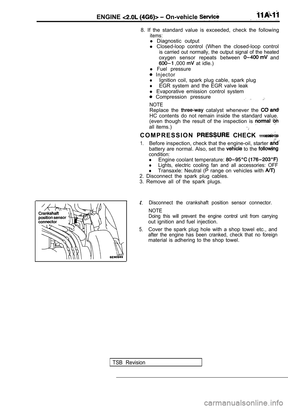
4.
5.
Disconnect the crankshaft position sensor connector .
NOTE
Doing this will prevent the engine control unit fro m carrying
out ignition and fuel injection.
Cover the spark plug hole with a shop towel etc., a nd
after the engine has been cranked, check that no fo reign
material is adhering to the shop towel.
TSB Revision
Page 73 of 2103
ENGINE On-vehicle Service
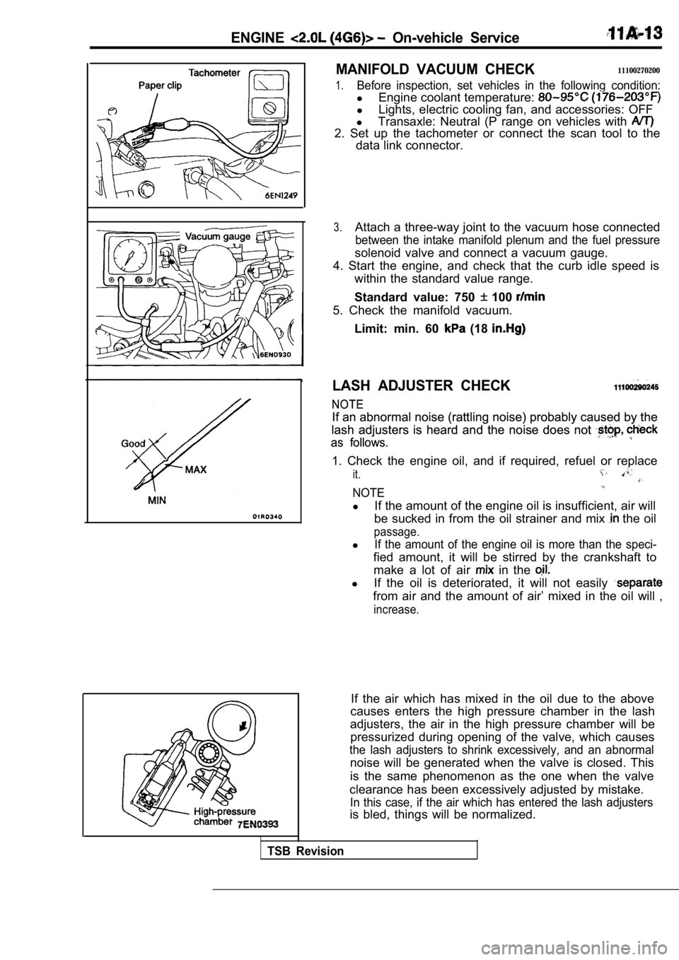
MANIFOLD VACUUM CHECK11100270200
1.Before inspection, set vehicles in the following condition:
lEngine coolant temperature:
lLights, electric cooling fan, and accessories: OFF
l Transaxle: Neutral (P range on vehicles with
2. Set up the tachometer or connect the scan tool t o the
data link connector.
3.Attach a three-way joint to the vacuum hose connect ed
between the intake manifold plenum and the fuel pressure
solenoid valve and connect a vacuum gauge.
4. Start the engine, and check that the curb idle s peed is
within the standard value range.
Standard value: 750
100
5. Check the manifold vacuum.
Limit: min. 60
(18
LASH ADJUSTER CHECK
NOTE
NOTE
If an abnormal noise (rattling noise) probably caus ed by the
If an abnormal noise (rattling noise) probably caus ed by the
lash adjusters is heard and the noise does not
lash adjusters is heard and the noise does not
as follows.
as follows.
1. Check the engine oil, and if required, refuel or replace
it.
NOTE
lIf the amount of the engine oil is insufficient, ai r will
be sucked in from the oil strainer and mix
the oil
passage.
lIf the amount of the engine oil is more than the sp eci-
fied amount, it will be stirred by the crankshaft to
make a lot of air
in the
l If the oil is deteriorated, it will not easily
from air and the amount of air’ mixed in the oil wi ll ,
increase.
If the air which has mixed in the oil due to the ab ove
causes enters the high pressure chamber in the lash
adjusters, the air in the high pressure chamber wil l be
pressurized during opening of the valve, which caus es
the lash adjusters to shrink excessively, and an abnormal
noise will be generated when the valve is closed. T his
is the same phenomenon as the one when the valve
clearance has been excessively adjusted by mistake.
In this case, if the air which has entered the lash adjusters
is bled, things will be normalized.
TSB Revision
Page 136 of 2103
ENGINE OVERHAUL Rocker, Arms
Camshaft sprocket side
sidecamshaft
Dowel pin
n0
Cap number
Symbol identifying
intake or exhaust
0
Camshaft sprocket side1197 810 12
2 6
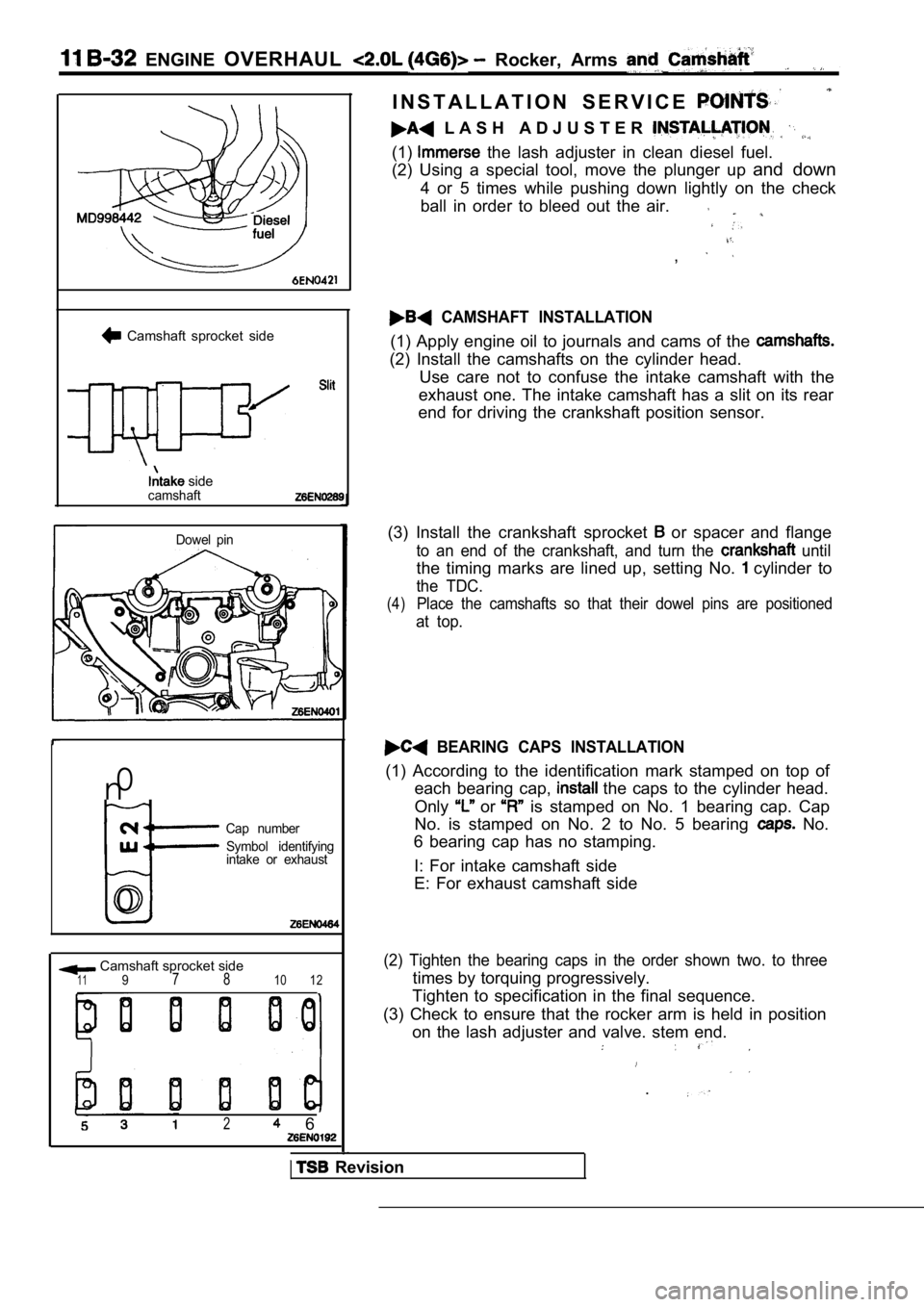
I N S T A L L A T I O N S E R V I C E
L A S H A D J U S T E R
(1) the lash adjuster in clean diesel fuel.
(2) Using a special tool, move the plunger up and down
4 or 5 times while pushing down lightly on the chec k
ball in order to bleed out the air.
,
CAMSHAFT INSTALLATION
(1) Apply engine oil to journals and cams of the
(2) Install the camshafts on the cylinder head. Use care not to confuse the intake camshaft with th e
exhaust one. The intake camshaft has a slit on its rear
end for driving the crankshaft position sensor.
(3) Install the crankshaft sprocket
or spacer and flange
to an end of the crankshaft, and turn the until
the timing marks are lined up, setting No. cylinder to
the TDC.
(4)Place the camshafts so that their dowel pins are po sitioned
at top.
BEARING CAPS INSTALLATION
(1) According to the identification mark stamped on top of
each bearing cap,
the caps to the cylinder head.
Only
or is stamped on No. 1 bearing cap. Cap
No. is stamped on No. 2 to No. 5 bearing
No.
6 bearing cap has no stamping.
I: For intake camshaft side
E: For exhaust camshaft side
(2) Tighten the bearing caps in the order shown two . to three
times by torquing progressively.
Tighten to specification in the final sequence.
(3) Check to ensure that the rocker arm is held in position
on the lash adjuster and valve. stem end.
.
Revision
Page 138 of 2103
11 ENGINE OVERHAUL Rocker
.
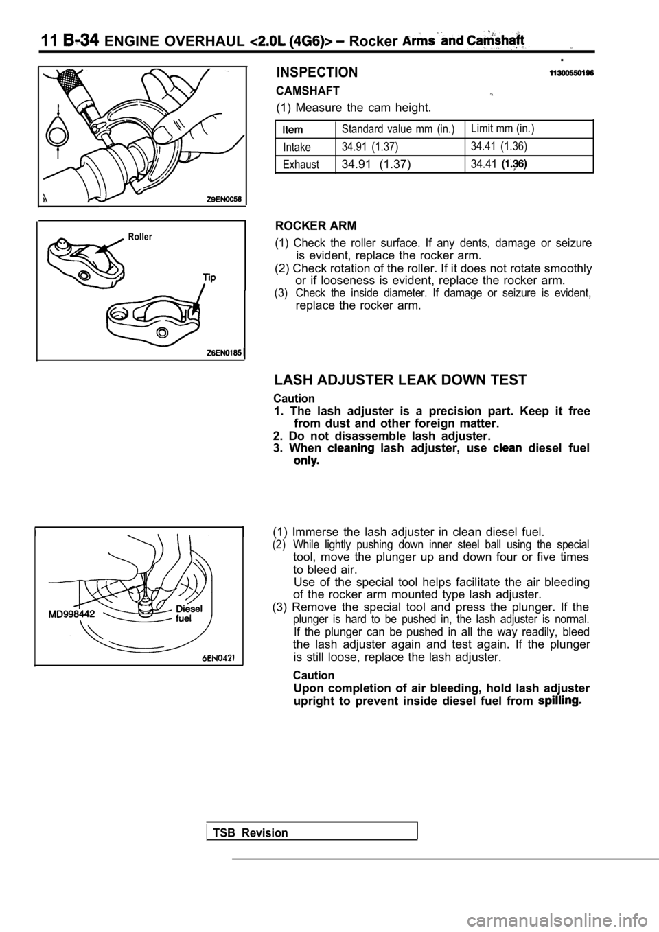
INSPECTION
CAMSHAFT
(1) Measure the cam height.
Roller
Standard value mm (in.)Limit mm (in.)
Intake 34.91 (1.37) 34.41 (1.36)
Exhaust
34.91 (1.37)34.41
ROCKER ARM
(1) Check the roller surface. If any dents, damage or seizure
is evident, replace the rocker arm.
(2) Check rotation of the roller. If it does not ro tate smoothly
or if looseness is evident, replace the rocker arm.
(3) Check the inside diameter. If damage or seizure is evident,
replace the rocker arm.
LASH ADJUSTER LEAK DOWN TEST
Caution
1. The lash adjuster is a precision part. Keep it f ree
from dust and other foreign matter.
2. Do not disassemble lash adjuster.
3. When
lash adjuster, use diesel fuel
(1) Immerse the lash adjuster in clean diesel fuel.
(2)While lightly pushing down inner steel ball using t he special
tool, move the plunger up and down four or five tim es
to bleed air. Use of the special tool helps facilitate the air bl eeding
of the rocker arm mounted type lash adjuster.
(3) Remove the special tool and press the plunger. If the
plunger is hard to be pushed in, the lash adjuster is normal.
If the plunger can be pushed in all the way readily, bleed
the lash adjuster again and test again. If the plun ger
is still loose, replace the lash adjuster.
Caution
Upon completion of air bleeding, hold lash adjuster
upright to prevent inside diesel fuel from
TSB Revision
Page 161 of 2103
ENGINE OVERHAUL
11300850104
(1) Replace piston ii or seizure is evident
its surfaces (especially surface). Replace the
piston if it is cracked.
PISTON PIN
(1) the piston pin the pin hole a
You should feel a slight resistance. the
pin if it can be easily inserted or there ‘is .
(2) The piston and piston pin must be replaced
bly.
PISTON RING
(1) Check ‘the ring for
and replace if defects are evident: piston
has been replaced with a
one, the piston
also be replaced with new ones.
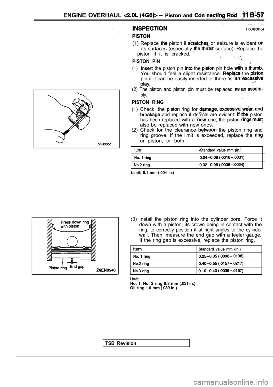
(2) Check for the clearance
the piston ring and
ring groove. If the limit is exceeded, replace the
or piston, or both.
Item
No. 1 ring
ring
Limit: 0.1 mm
in.)
-Standard value mm (in.)
(3) Install the piston ring into the cylinder bore. Force it
down with a piston, its crown being in contact with the
ring, to correctly position it at right angles to the cylinder
wall. Then, measure the end gap with a feeler gauge .
If the ring gap is excessive, replace the piston ri ng.
Standard value mm (in.)
No. 1 ring
ring
ring
Limit:No. 1, No. 2 ring 0.8 mm in.)
Oil ring 1.0 mm in.)
TSB Revision
Page 180 of 2103
ENGINE On-vehicle Service
POWER STEERING OIL PUMP AND A/C
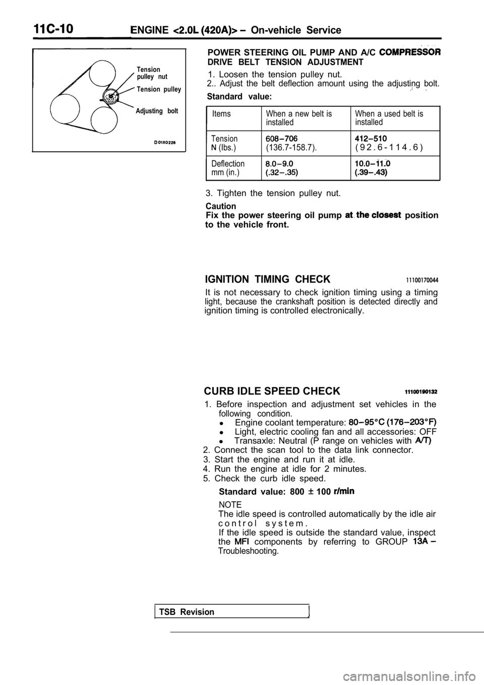
DRIVE BELT TENSION ADJUSTMENTTensionpulley nut1. Loosen the tension pulley nut.
Tension pulley2.. Adjust the belt deflection amount using the adj usting bolt.
Standard value:
Adjusting boltItems
Tension
(Ibs.)
Deflection
mm (in.) When a new belt is When a used belt is
installed
installed(136.7-158.7).( 9 2 . 6 - 1 1 4 . 6 )
3. Tighten the tension pulley nut.
Caution
Fix the power steering oil pump position
to the vehicle front.
IGNITION TIMING CHECK11100170044
It is not necessary to check ignition timing using a timing
light, because the crankshaft position is detected directly and
ignition timing is controlled electronically.
CURB IDLE SPEED CHECK
1. Before inspection and adjustment set vehicles in the
following condition.
lEngine coolant temperature:
lLight, electric cooling fan and all accessories: OF F
l Transaxle: Neutral (P range on vehicles with
2. Connect the scan tool to the data link connector .
3. Start the engine and run it at idle.
4. Run the engine at idle for 2 minutes.
5. Check the curb idle speed.
Standard value: 800
100
NOTE
The idle speed is controlled automatically by the i dle air
c o n t r o l s y s t e m . If the idle speed is outside the standard value, in spect
the
components by referring to GROUP
Troubleshooting.
TSB Revision
Page 181 of 2103
ENGINE On-vehicle Service
IDLE MIXTURE CHECK
11100210081
1.Before inspection, set vehicles in the following co ndition:
lEngine coolant temperature:
l Lights, electric cooling fan and all accessories: O FF
lTransaxle: Neutral (P range on vehicles with
2.After turning the ignition switch to OFF, connect t he scan
tool to the data link connector.
3.Start the engine and run it at 2,500 for 2 minutes.
4. Set the CO, HC tester.
5. Check the CO contents and the HC contents at idl e.
Standard value:
CO contents: 0.5% or less
HC contents: 100 ppm or less
6. If the idle speed is outside the standard value, check
the following items: l Diagnostic output
l Closed-loop control (When the closed-loop control
is carried out normally, the output signal of the h eated
oxygen sensor repeats between and
,000 at idle.)
l Fuel pressure
I n j e c t o r
lIgnition coil, spark plug cable, spark plug
lEGR system and the EGR valve leak
l Evaporative emission control system
Compression pressure
NOTE
Replace the three-way catalyst whenever the CO and
HC contents do not remain inside the standard value .
(even though the result of the inspection is normal on
all items.)
COMPRESSION PRESSURE CHECK
1.Before inspection, check that the engine oil, start er and
battery are normal. Also, set the vehicle to the fo llowing
condition:
lEngine coolant temperature:
lLights, electric cooling fan and all accessories: O FF
lTransaxle: Neutral (P range on vehicle with
2. Disconnect the spark plug cables.
3. Remove all spark plugs.
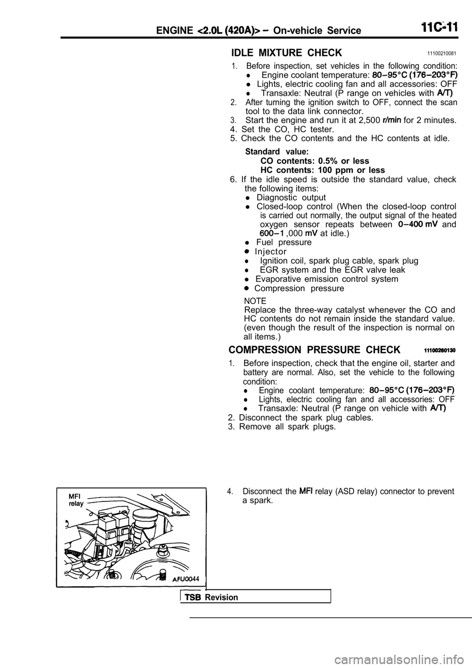
4.Disconnect the relay (ASD relay) connector to prevent
a spark.
4 4
Revision