display MITSUBISHI SPYDER 1990 Service Repair Manual
[x] Cancel search | Manufacturer: MITSUBISHI, Model Year: 1990, Model line: SPYDER, Model: MITSUBISHI SPYDER 1990Pages: 2103, PDF Size: 68.98 MB
Page 8 of 2103
G E N E R A L How to Use Troubleshooting/Inspection Service Points
Troubleshooting of electronic control systems for which the scan tool the basic outline
described below. Furthermore, even in systems for w hich the scan tool cannot be used, part of these
systems still follow this outline.
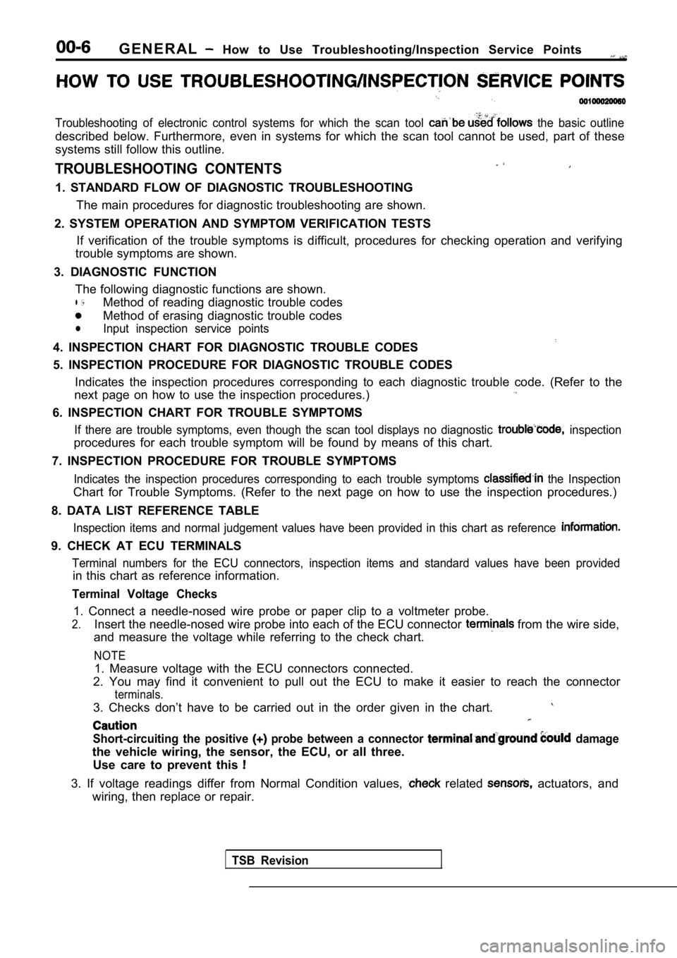
TROUBLESHOOTING CONTENTS
1. STANDARD FLOW OF DIAGNOSTIC TROUBLESHOOTING
The main procedures for diagnostic troubleshooting are shown.
2. SYSTEM OPERATION AND SYMPTOM VERIFICATION TESTS If verification of the trouble symptoms is difficul t, procedures for checking operation and verifying
trouble symptoms are shown.
3. DIAGNOSTIC FUNCTION The following diagnostic functions are shown.
l ,Method of reading diagnostic trouble codes
Method of erasing diagnostic trouble codes
lInput inspection service points
4. INSPECTION CHART FOR DIAGNOSTIC TROUBLE CODES
5. INSPECTION PROCEDURE FOR DIAGNOSTIC TROUBLE CODE S
Indicates the inspection procedures corresponding t o each diagnostic trouble code. (Refer to the
next page on how to use the inspection procedures.)
6. INSPECTION CHART FOR TROUBLE SYMPTOMS
If there are trouble symptoms, even though the scan tool displays no diagnostic inspection
procedures for each trouble symptom will be found b y means of this chart.
7. INSPECTION PROCEDURE FOR TROUBLE SYMPTOMS
Indicates the inspection procedures corresponding t o each trouble symptoms the Inspection
Chart for Trouble Symptoms. (Refer to the next page on how to use the inspection procedures.)
8. DATA LIST REFERENCE TABLE
Inspection items and normal judgement values have b een provided in this chart as reference
9. CHECK AT ECU TERMINALS
Terminal numbers for the ECU connectors, inspection items and standard values have been provided
in this chart as reference information.
Terminal Voltage Checks
1. Connect a needle-nosed wire probe or paper clip to a voltmeter probe.
2.Insert the needle-nosed wire probe into each of the ECU connector from the wire side,
and measure the voltage while referring to the chec k chart.
NOTE
1. Measure voltage with the ECU connectors connecte d.
2. You may find it convenient to pull out the ECU t o make it easier to reach the connector
terminals.
3. Checks don’t have to be carried out in the order given in the chart.
Short-circuiting the positive probe between a connector damage
the vehicle wiring, the sensor, the ECU, or all thr ee.
Use care to prevent this
3. If voltage readings differ from Normal Condition values, related actuators, and
wiring, then replace or repair.
TSB Revision
Page 35 of 2103
GENERAL Lubrication arid Maintenance,
00100120067
Maintenance and lubrication service recommenda-
tions have been compiled to provide maximum
protection for the vehicle owner’s investment
against all reasonable types of driving conditions.
Since these conditions vary with the individual ve-
hicle owner’s driving habits, the area in which the
vehicle is operated and the type of to which
the vehicle is subjected, it is necessary to prescr ibe
lubrication and maintenance service on a time fre-
quency as well as mileage interval basis.
Oils, lubricants and greases are classified and
graded according to standards recommended by
the Society of Automotive Engineers (SAE), the
American Petroleum Institute (API) and the National
Lubricating Grease Institute (NLGI).
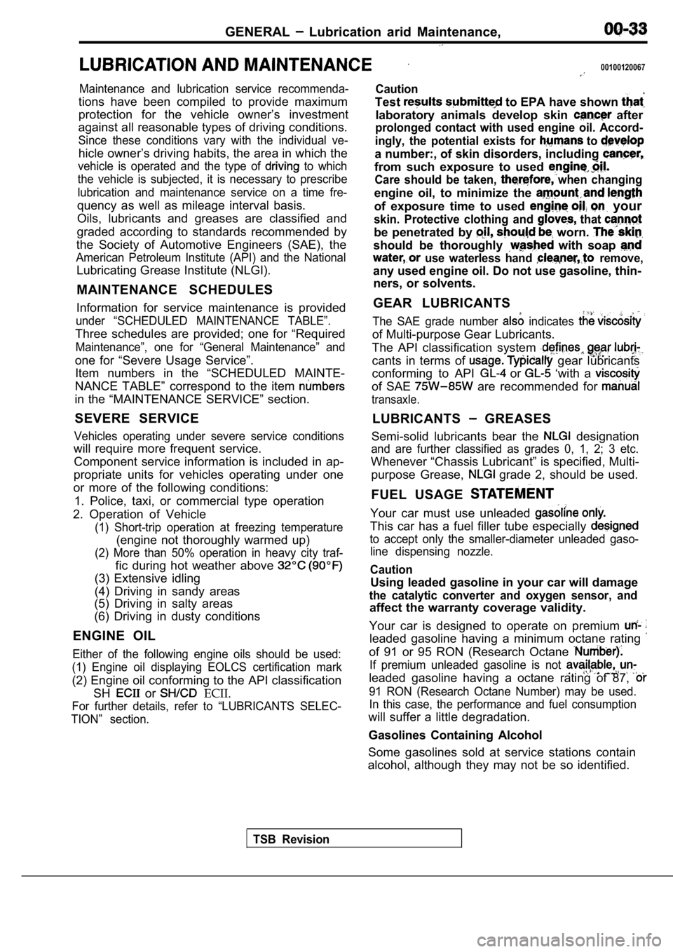
MAINTENANCE SCHEDULES
Information for service maintenance is provided
under “SCHEDULED MAINTENANCE TABLE”.
Three schedules are provided; one for “Required
Maintenance”, one for “General Maintenance” and
one for “Severe Usage Service”. Item numbers in the “SCHEDULED MAINTE-
NANCE TABLE” correspond to the item
in the “MAINTENANCE SERVICE” section.
SEVERE SERVICE
Vehicles operating under severe service conditions
will require more frequent service. Component service information is included in ap-
propriate units for vehicles operating under one
or more of the following conditions:
1. Police, taxi, or commercial type operation
2. Operation of Vehicle
(1) Short-trip operation at freezing temperature
(engine not thoroughly warmed up)
(2) More than 50% operation in heavy city traf-
fic during hot weather above
(3) Extensive idling
(4) Driving in sandy areas
(5) Driving in salty areas
(6) Driving in dusty conditions
ENGINE OIL
Either of the following engine oils should be used:
(1) Engine oil displaying EOLCS certification mark
(2) Engine oil conforming to the API classification SH
or ECII.
For further details, refer to “LUBRICANTS SELEC-
TION” section.
Caution
Test to EPA have shown
laboratory animals develop skin after
prolonged contact with used engine oil. Accord-
ingly, the potential exists for
to
a number:, of skin disorders, including
from such exposure to used
Care should be taken, when changing
engine oil, to minimize the
of exposure time to used your
skin. Protective clothing and that
be penetrated by worn.
should be thoroughly with soap
use waterless hand remove,
any used engine oil. Do not use gasoline, thin- ners, or solvents.
GEAR LUBRICANTS
The SAE grade number indicates
of Multi-purpose Gear Lubricants.
The API classification system
cants in terms of gear lubricants
conforming to API
or ‘with a
of SAE are recommended for
transaxle.
LUBRICANTS GREASES
Semi-solid lubricants bear the
designation
and are further classified as grades 0, 1, 2; 3 etc .
Whenever “Chassis Lubricant” is specified, Multi-
purpose Grease,
grade 2, should be used.
FUEL USAGE
Your car must use unleaded
This car has a fuel filler tube especially
to accept only the smaller-diameter unleaded gaso- line dispensing nozzle.
Caution
Using leaded gasoline in your car will damage
the catalytic converter and oxygen sensor, and
affect the warranty coverage validity.
Your car is designed to operate on premium
leaded gasoline having a minimum octane rating
of 91 or 95 RON (Research Octane
If premium unleaded gasoline is not
leaded gasoline having a octane rating of 87,
91 RON (Research Octane Number) may be used. In this case, the performance and fuel consumption
will suffer a little degradation.
Gasolines Containing Alcohol
Some gasolines sold at service stations contain
alcohol, although they may not be so identified.
TSB Revision
Page 36 of 2103
Lubrication and
GENERAL Lubricants and Lubricant Capacities Table
Use of fuels containing alcohol is not recommended
unless the nature of the blend can be determined
as being satisfactory.
Gasohol
A mixture of 10% ethanol (grain alcohol)
and 90% unleaded gasoline may be used in your
car.
If problems are experienced as a result
of using gasohol, it is recommended that the car
be operated on gasoline.
Methanol Do not use gasolines containing
methanol (wood alcohol). Use of this type of alcohol
can result in vehicle performance deterioration and
damage critical parts in the fuel system compo-
nents. Fuel system damage and performance prob-
lems, resulting from the use of gasolines containin g
methanol, may not be covered by the new car war-
ranty.
Gasolines containing
Ether)
Unleaded gasoline containing 15% or
may be used in car. Fuel containing MTBE
over 15% vol. may cause reduced engine perfor-
mance and produce vapor lock or hard starting.
MATERIALS
TO FUEL
Indiscriminate use of fuel system -cleaning’
should be avoided. Many of these materials in-
tended for gum and varnish removal
highly active solvents or similar ingredients that
can be harmful to gasket and diaphragm materials
used in fuel system component
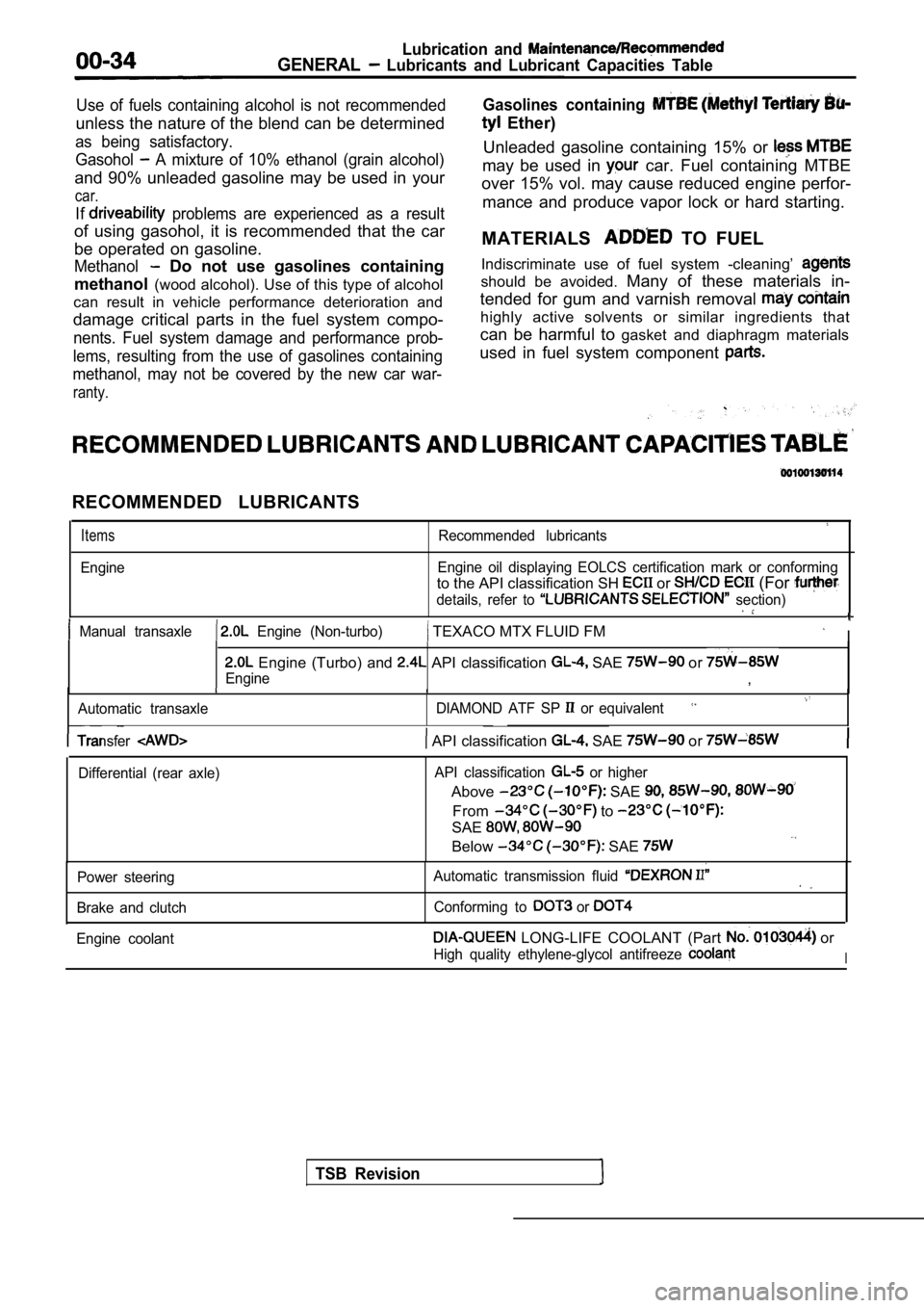
RECOMMENDED LUBRICANTS
Items
Engine
Recommended lubricants
Engine oil displaying EOLCS certification mark or c onforming
to the API classification SH or (For
details, refer to section)
Manual transaxle Engine (Non-turbo) TEXACO MTX FLUID FM I
Engine (Turbo) and API classification SAE or
Engine,
Automatic transaxle DIAMOND ATF SP or equivalent
TSB Revision
Transfer API classification SAE or
Differential (rear axle)API classification or higher
Above SAE
From to
SAE
Below SAE
Power steering
Brake and clutch Automatic transmission fluid
Conforming to or
Engine coolant LONG-LIFE COOLANT (Part or
High quality ethylene-glycol antifreeze I
Page 37 of 2103
GENERAL Recommended Lubricants and Lubricant Table
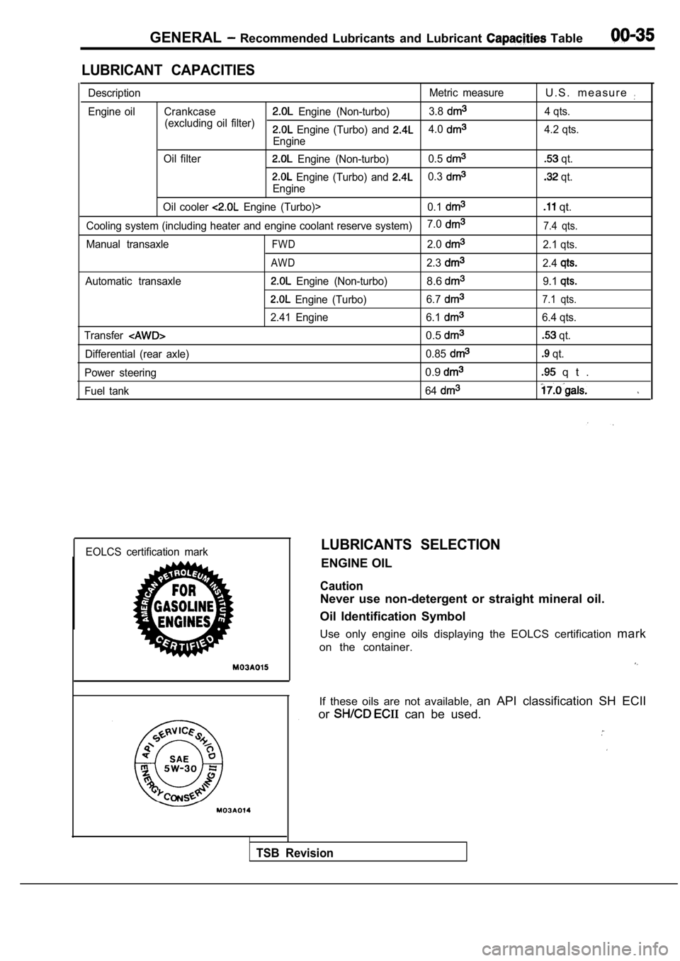
LUBRICANT CAPACITIES
DescriptionMetric measureU . S . m e a s u r e
Engine oil Crankcase Engine (Non-turbo)3.8
(excluding oil filter) 4 qts. Engine (Turbo) and 4.0
Engine4.2 qts.
Oil filter
Engine (Non-turbo) 0.5 qt.
Engine (Turbo) and 0.3
Engine
qt.
Oil cooler
Engine (Turbo)> 0.1 qt.
Cooling system (including heater and engine coolant reserve system)7.07.4 qts.
Manual transaxleFWD2.02.1 qts.
AWD2.32.4
Automatic transaxle Engine (Non-turbo)8.69.1
Engine (Turbo)
6.77.1 qts.
2.41 Engine 6.16.4 qts.
Transfer
0.5 qt.
Differential (rear axle) 0.85
qt.
Power steering
0.9 q t .
Fuel tank 64
EOLCS certification markLUBRICANTS SELECTION
ENGINE OIL
Caution
Never use non-detergent or straight mineral oil.
Oil Identification Symbol
Use only engine oils displaying the EOLCS certifica tion mark
on the container.
If these oils are not available, an API classification SH ECII
or
can be used.
TSB Revision
Page 374 of 2103
ENGINE LUBRICATION General Information/Lubricants
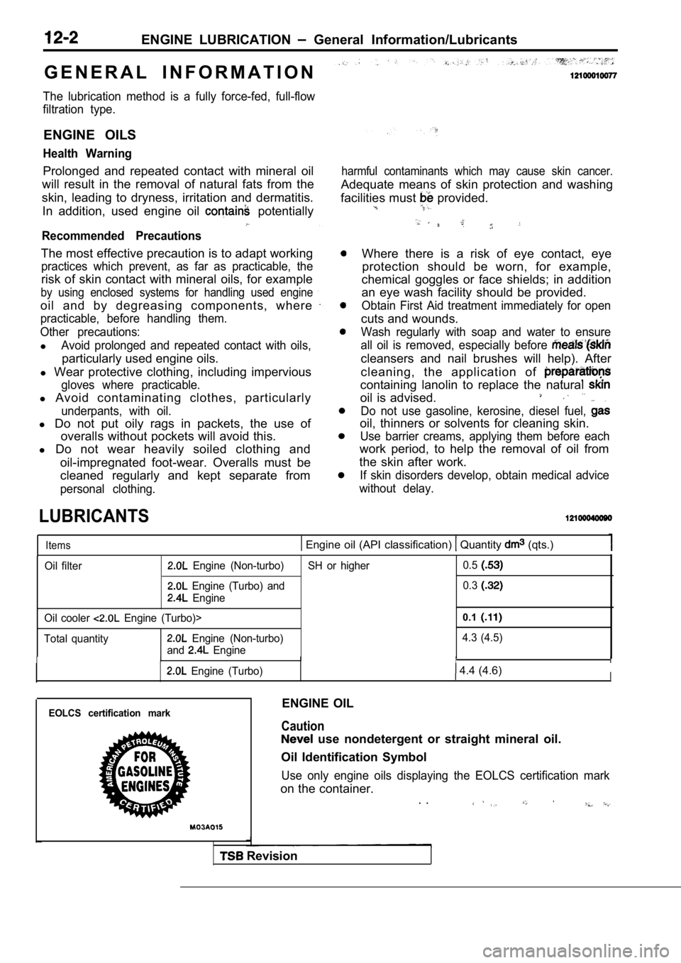
G E N E R A L I N F O R M A T I O N
The lubrication method is a fully force-fed, full-f low
filtration type.
ENGINE OILS
Health Warning
Prolonged and repeated contact with mineral oil
will result in the removal of natural fats from the
skin, leading to dryness, irritation and dermatitis .
In addition, used engine oil
potentially
Recommended Precautions
The most effective precaution is to adapt working
practices which prevent, as far as practicable, the
risk of skin contact with mineral oils, for example
by using enclosed systems for handling used engine
oil and by degreasing components, where
practicable, before handling them.
Other precautions:
lAvoid prolonged and repeated contact with oils,
particularly used engine oils.
l Wear protective clothing, including impervious
gloves where practicable.
l Avoid contaminating clothes, particularly
underpants, with oil.
l Do not put oily rags in packets, the use of
overalls without pockets will avoid this.
l Do not wear heavily soiled clothing and
oil-impregnated foot-wear. Overalls must be
cleaned regularly and kept separate from
personal clothing.
LUBRICANTS
harmful contaminants which may cause skin cancer.
Adequate means of skin protection and washing
facilities must
provided.
Where there is a risk of eye contact, eye protection should be worn, for example,
chemical goggles or face shields; in addition
an eye wash facility should be provided.
Obtain First Aid treatment immediately for open
cuts and wounds.
Wash regularly with soap and water to ensure
all oil is removed, especially before
cleansers and nail brushes will help). After
cleaning, the application of
containing lanolin to replace the natural
oil is advised.. .
Do not use gasoline, kerosine, diesel fuel,
oil, thinners or solvents for cleaning skin.
Use barrier creams, applying them before each
work period, to help the removal of oil from
the skin after work.
If skin disorders develop, obtain medical advice
without delay.
Items Engine oil (API classification) Quantity (qts.)
Oil filter Engine (Non-turbo)
Engine (Turbo) and
Engine
Oil cooler
Engine (Turbo)>
Total quantity
Engine (Non-turbo)
and
Engine SH or higher
0.5
0.3
0.1
4.3 (4.5)
IIIII
Engine (Turbo) 4.4 (4.6)I
EOLCS certification markENGINE OIL
Caution
use nondetergent or straight mineral oil.
Oil Identification Symbol
Use only engine oils displaying the EOLCS certifica tion mark
on the container.
. .
Revision
Page 391 of 2103
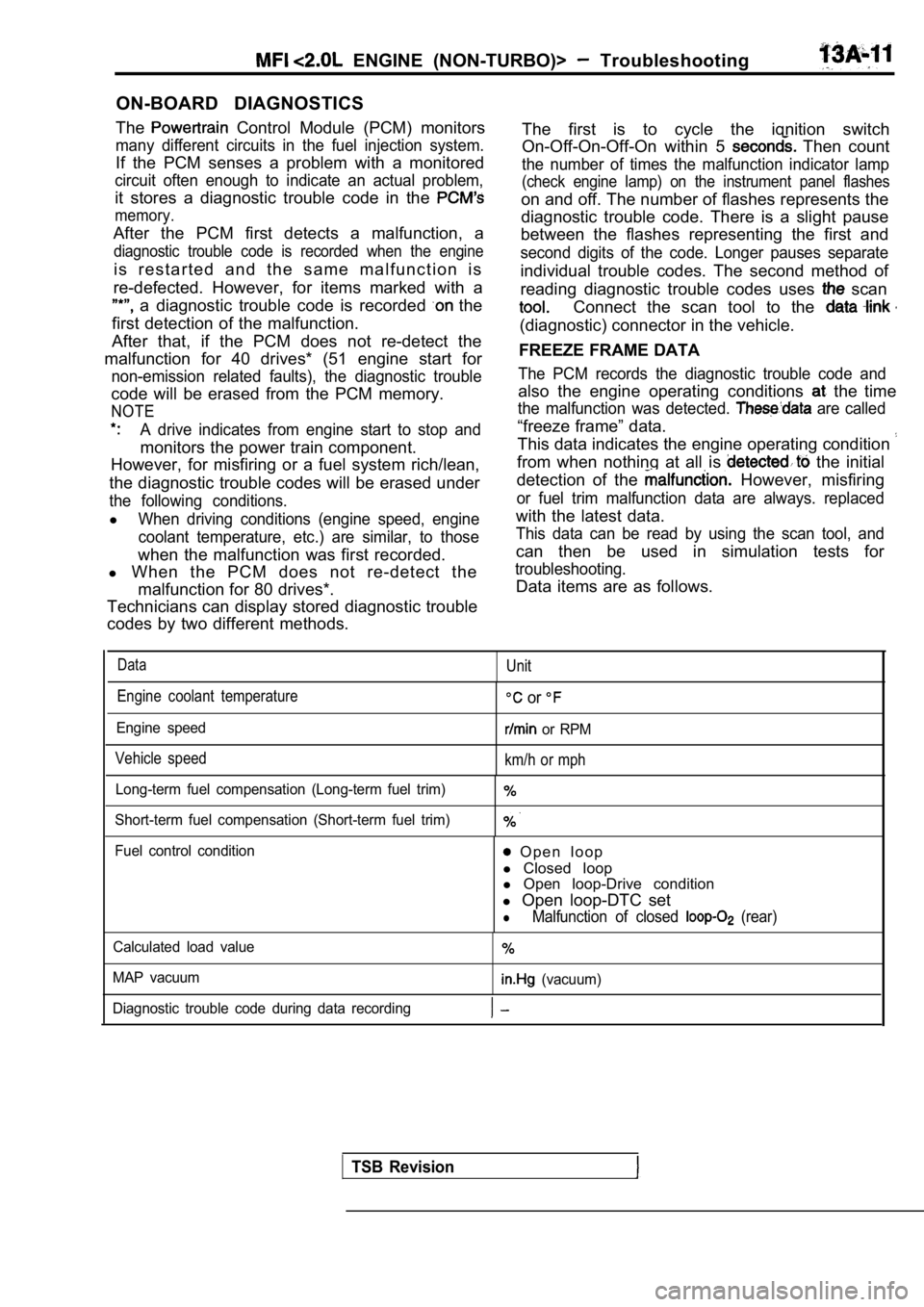
ON-BOARD DIAGNOSTICS
The
Control Module (PCM) monitors
many different circuits in the fuel injection syste m.
If the PCM senses a problem with a monitored
circuit often enough to indicate an actual problem,
it stores a diagnostic trouble code in the
memory.
After the PCM first detects a malfunction, a
diagnostic trouble code is recorded when the engine
i s r e s t a r t e d a n d t h e s a m e m a l f u n c t i o n i s
re-defected. However, for items marked with a
a diagnostic trouble code is recorded the
first detection of the malfunction.
After that, if the PCM does not re-detect the
malfunction for 40 drives* (51 engine start for
non-emission related faults), the diagnostic troubl e
code will be erased from the PCM memory.
NOTE
A drive indicates from engine start to stop and
monitors the power train component.
However, for misfiring or a fuel system rich/lean,
the diagnostic trouble codes will be erased under
the following conditions.
lWhen driving conditions (engine speed, engine
coolant temperature, etc.) are similar, to those
when the malfunction was first recorded.
l When the PCM does not re-detect the
malfunction for 80 drives*.
Technicians can display stored diagnostic trouble
codes by two different methods.
ENGINE (NON-TURBO)> Troubleshooting
The first is to cycle the ignition switch
On-Off-On-Off-On within 5
Then count
the number of times the malfunction indicator lamp
(check engine lamp) on the instrument panel flashes
on and off. The number of flashes represents the
diagnostic trouble code. There is a slight pause
between the flashes representing the first and
second digits of the code. Longer pauses separate
individual trouble codes. The second method of
reading diagnostic trouble codes uses
scan
Connect the scan tool to the
(diagnostic) connector in the vehicle.
FREEZE FRAME DATA
The PCM records the diagnostic trouble code and
also the engine operating conditions the time
the malfunction was detected. are called
“freeze frame” data.
This data indicates the engine operating condition
from when nothing at all is the initial
detection of the
However, misfiring
or fuel trim malfunction data are always. replaced
with the latest data.
This data can be read by using the scan tool, and
can then be used in simulation tests for
troubleshooting.
Data items are as follows.
DataUnit
Engine coolant temperature
Engine speed
Vehicle speed
or
or RPM
km/h or mph
Long-term fuel compensation (Long-term fuel trim)
Short-term fuel compensation (Short-term fuel trim)
Fuel control condition O p e n l o o p
l Closed loop
l Open loop-Drive condition
l Open loop-DTC set
lMalfunction of closed (rear)
Calculated load value
MAP vacuum
(vacuum)
Diagnostic trouble code during data recording
TSB Revision
Page 421 of 2103
ENGINE (NON-TURBO)>
SCAN SENSOR READ TEST list)
65 Vehicle speed sensor
l Is vehicle speed displayed during driving?
No
Check the following
OK
Check trouble symptom.
OK
harness wire module connector.
OK
Yes R e p l a c e t h e P C M .
N G Repair
NG Repair
Check the automatic transaxle control system.
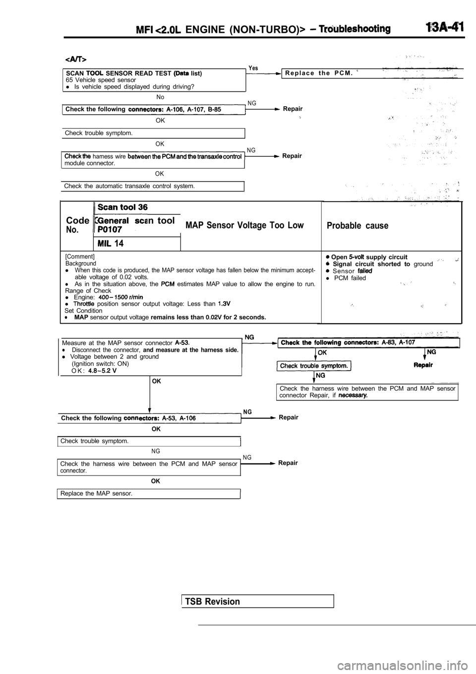
Code General scan tool
No.MAP Sensor Voltage Too Low
14
[Comment]Background
lWhen this code is produced, the MAP sensor voltage has fallen below the minimum accept-able voltage of 0.02 volts.lAs in the situation above, the estimates MAP value to allow the engine to run.
Range of Check
l Engine:
l position sensor output voltage: Less than Set ConditionlMAP sensor output voltage remains less than for 2 seconds.
Probable cause
Open supply circuit Signal circuit shorted to ground Sensor l PCM failed
Measure at the MAP sensor connector lDisconnect the connector, and measure at the harness side.l Voltage between 2 and ground
(Ignition switch: ON)
O K :
OKCheck the harness wire between the PCM and MAP sens or
connector Repair, if
NGCheck the following Repair
OK
Check trouble symptom.
N G NG
Check the harness wire between the PCM and MAP sens or Repairconnector.
OK
Replace the MAP sensor.
TSB Revision
Page 481 of 2103
ENGINE (NON-TURBO)>
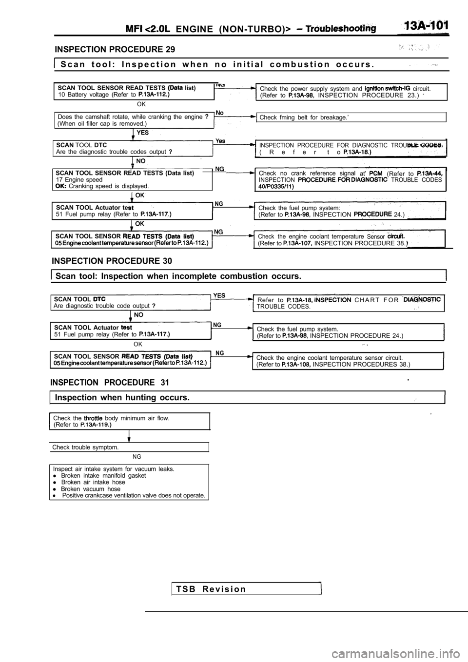
INSPECTION PROCEDURE 29
S c a n t o o l : I n s p e c t i o n w h e n n o i n i t i a l c o m b u s t i o n oc c u r s .
SCAN TOOL SENSOR READ TESTS
list)
10 Battery voltage (Refer to
OK
Check the power supply system and circuit.
(Refer to INSPECTION PROCEDURE 23.)
Does the camshaft rotate, while cranking the engine (When oil filler cap is removed.) Check fming belt for breakage.’
SCAN TOOLDTC
INSPECTION PROCEDURE FOR DIAGNOSTIC TROUBLE CODES.Are the diagnostic trouble codes output( R e f e r t o
SCAN TOOL SENSOR READ TESTS (Data list) Check no crank reference signal
at’(Refer to 17 Engine speedINSPECTION TROUBLE CODES Cranking speed is displayed.
SCAN TOOL Actuator teNGCheck the fuel pump system:51 Fuel pump relay (Refer to (Refer to INSPECTION 24.)
SCAN TOOL SENSOR
Check theengine coolant temperatureSensor(Refer to INSPECTION PROCEDURE 38.)
INSPECTION PROCEDURE 30
Scan tool: Inspection when incomplete combustion o ccurs.
SCAN TOOL
Refer to C H A R T F O R Are diagnostic trouble code outputTROUBLE CODES.
SCAN TOOL Actuator NG
51 Fuel pump relay (Refer to Check the fuel pump system. (Refer to INSPECTION PROCEDURE 24.)
OK ,
SCAN TOOL SENSOR NGCheck the engine coolant temperature sensor circuit .
(Refer to INSPECTION PROCEDURES 38.)
INSPECTION PROCEDURE 31.
Inspection when hunting occurs.
,
Check the body minimum air flow.
(Refer to
Check trouble symptom.
NG
Inspect air intake system for vacuum leaks.
l Broken intake manifold gasket
l Broken air intake hose
l Broken vacuum hose
lPositive crankcase ventilation valve does not opera te.
T S B R e v i s i o n
Page 497 of 2103
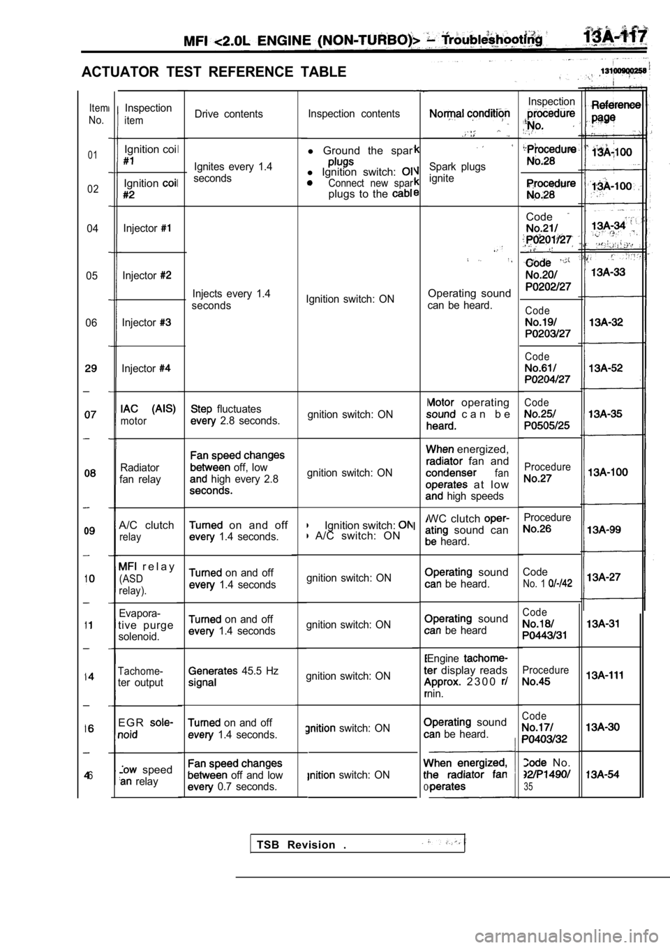
ACTUATOR TEST REFERENCE TABLE
Drive contentsInspection contents
l
Ground the spar
l Ignition switch: Connect new sparplugs to the
Spark plugs
ignite
Ignition switch: ONOperating sound
can be heard.
gnition switch: ON
operating
c a n b e
gnition switch: ON
energized,
fan and
fan
a t l o w
high speeds
Ignition switch: A/C switch: ON WC clutch sound can
heard.
gnition switch: ON
sound
be heard.
gnition switch: ON
sound
be heard
gnition switch: ON Engine
display reads
2 3 0 0
nin.
switch: ON
switch: ON
I
I
0
sound
be heard.
Item
No.
01
02
04
05
06
6
Inspection
Code
,
Code
Code
Code
Procedure
Procedure
Code
No. 1
Code
Procedure
Code
No.
35
Inspection
item
Ignition coi
Ignition
Injector
Injector
Injector
Injector
motor
Radiator
fan relay
A/C clutch
relay
r e l a y
(ASD
relay).
Evapora-
tive purge
solenoid.
Tachome-
ter output
E G R
speed
relay Ignites every 1.4
seconds
I
I
Injects every 1.4
seconds
fluctuates
2.8 seconds.
off, low
high every 2.8
on and off
1.4 seconds.
on and off
1.4 seconds
on and off
1.4 seconds
45.5 Hz
on and off
1.4 seconds.
off and low
0.7 seconds.
TSB Revision .
Page 499 of 2103
ENGINE (NON-TURBO)>
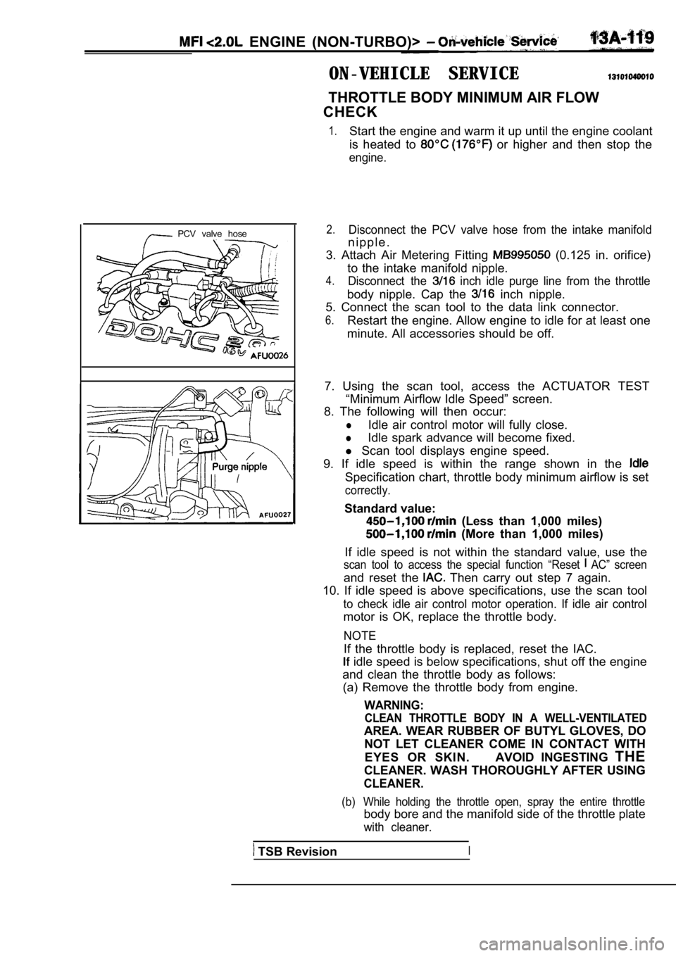
ON-VEHICLE SERVICE
THROTTLE BODY MINIMUM AIR FLOW
CHECK
1.Start the engine and warm it up until the engine co olant
is heated to
or higher and then stop the
engine.
PCV valve hose2.Disconnect the PCV valve hose from the intake manif old
n i p p l e .
3. Attach Air Metering Fitting
(0.125 in. orifice)
to the intake manifold nipple.
4.Disconnect the inch idle purge line from the throttle
body nipple. Cap the inch nipple.
5. Connect the scan tool to the data link connector .
6.Restart the engine. Allow engine to idle for at least one
minute. All accessories should be off.
7. Using the scan tool, access the ACTUATOR TEST “Minimum Airflow Idle Speed” screen.
8. The following will then occur:
lIdle air control motor will fully close.
lIdle spark advance will become fixed.
l Scan tool displays engine speed.
9. If idle speed is within the range shown in the
Specification chart, throttle body minimum airflow is set
correctly.
Standard value:
(Less than 1,000 miles)
(More than 1,000 miles)
If idle speed is not within the standard value, use the
scan tool to access the special function “Reset AC” screen
and reset the Then carry out step 7 again.
10. If idle speed is above specifications, use the scan tool
to check idle air control motor operation. If idle air control
motor is OK, replace the throttle body.
NOTE
If the throttle body is replaced, reset the IAC.
idle speed is below specifications, shut off the e ngine
and clean the throttle body as follows: (a) Remove the throttle body from engine.
WARNING:
CLEAN THROTTLE BODY IN A WELL-VENTILATED
AREA. WEAR RUBBER OF BUTYL GLOVES, DO
NOT LET CLEANER COME IN CONTACT WITH
EYES OR SKIN. AVOID INGESTING THE
CLEANER. WASH THOROUGHLY AFTER USING
CLEANER.
(b) While holding the throttle open, spray the entir e throttle
body bore and the manifold side of the throttle plate
with cleaner.
TSB RevisionI