fuel type MITSUBISHI SPYDER 1990 Service Repair Manual
[x] Cancel search | Manufacturer: MITSUBISHI, Model Year: 1990, Model line: SPYDER, Model: MITSUBISHI SPYDER 1990Pages: 2103, PDF Size: 68.98 MB
Page 5 of 2103
GENERAL How to Use This
HOW TO USE THIS MANUAL
MAINTENANCE, REPAIR AND
SERVICING EXPLANATIONS
This manual provides explanations, etc. concerning procedures for the inspection, maintenance, repair
and servicing of the subject model. Unless other-
wise specified, each service procedure covers all
models. Procedures covering specific models are
identified by the model codes, or similar designati on
(engine type, transaxle type, etc.). A description
of these designations is covered in this manual
under “VEHICLE IDENTIFICATION”.
ON-VEHICLE SERVICE
“On-vehicle Service” are procedures for performing
inspections and adjustments of particularly impor-
tant locations with regard to the construction and
for maintenance and servicing, but other inspec-
tions (for looseness, play, cracking, damage, etc.
must also be performed.
SERVICE PROCEDURES
The service steps are arranged in numerical order
and attention must to be paid in performing vehicle
service are described in detail in SERVICE POINTS.
TERMS DEFINITION
STANDARD VALUE
Indicates the value used as the standard for judgin g
the quality of a part or assembly on inspection
or the value to which the part or assembly is cor-
rected and adjusted. It is given by tolerance.
LIMIT
Indicates a maximum or minimum value, the part
or assembly should be kept within, in order to be functional. This value is established outside the
standard value range.
REFERENCE VALUE
Indicates the adjustment value prior to starting th e
work (presented in order to facilitate assembly and
adjustment procedures, and so they can be com-
pleted in a shorter time).
CAUTION
Indicates the presentation of information particula rly
vital to the worker during the performance of maint e-
nance and servicing procedures in order to avoid
the possibility of injury to the worker, or damage
to component parts, or a reduction of component
or vehicle function or performance, etc..
TIGHTENING TORQUE INDICATION
The tightening torque shown in this manual is a
basic value with a tolerance of
10% except the
following cases when the upper. and
of tightening torque are given. (1) The tolerance of the ‘basic value
10%.
(2) Special bolts or, the ‘like are
(3) Special tightening methods are used.
SPECIAL TOOL NOTE
When the MMC special tool is described, please
refer to the special tool
is located at the beginning of each group, for a
cross reference from the tool, number
to the special tool number that available in your
market..
MODEL INDICATIONS
The following abbreviations are used in this manual for classification of model types.
M/T
Indicates the manual transaxle, or models equipped with the manual transaxle.
A/T
Indicates the automatic transaxle, or models equip ped with the automatic transaxle.
MFI: Indicates the
fuel injection, or engines equipped with the fuel injection.
Turbo: Indicates the engine with turbocharger, or m odels equipped
such an
Non-turbo: Indicates the engine without turbocharger, or models equipped with, such anengine.
FWD: Indicates the front wheel drive vehicles.
AWD: Indicates the all wheel drive vehicles.
ABS: Indicates the anti-lock braking system or mode ls equipped with the
braking
Page 27 of 2103
G E N E R A L T o w i n g a n d
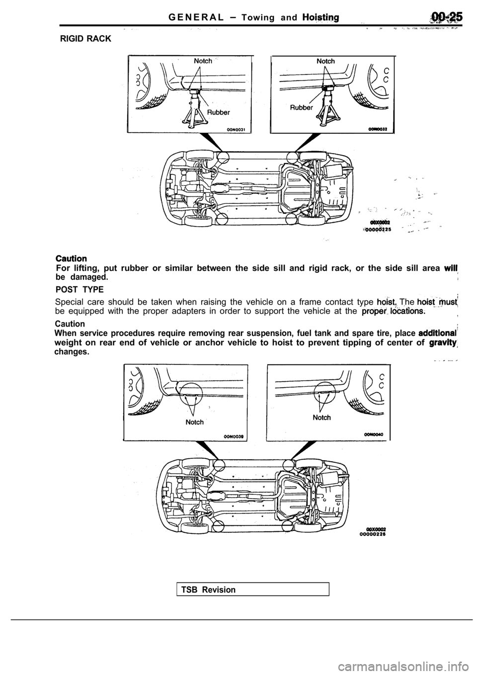
RIGID RACK
For lifting, put rubber or similar between the side sill and rigid rack, or the side sill area
be damaged.
POST TYPE
Special care should be taken when raising the vehicle on a frame contact type The
be equipped with the proper adapters in order to support the vehicle at the
Caution
When service procedures require removing rear suspe nsion, fuel tank and spare tire, place
weight on rear end of vehicle or anchor vehicle to hoist to prevent tipping of center of
changes.
TSB Revision
Page 35 of 2103
GENERAL Lubrication arid Maintenance,
00100120067
Maintenance and lubrication service recommenda-
tions have been compiled to provide maximum
protection for the vehicle owner’s investment
against all reasonable types of driving conditions.
Since these conditions vary with the individual ve-
hicle owner’s driving habits, the area in which the
vehicle is operated and the type of to which
the vehicle is subjected, it is necessary to prescr ibe
lubrication and maintenance service on a time fre-
quency as well as mileage interval basis.
Oils, lubricants and greases are classified and
graded according to standards recommended by
the Society of Automotive Engineers (SAE), the
American Petroleum Institute (API) and the National
Lubricating Grease Institute (NLGI).
MAINTENANCE SCHEDULES
Information for service maintenance is provided
under “SCHEDULED MAINTENANCE TABLE”.
Three schedules are provided; one for “Required
Maintenance”, one for “General Maintenance” and
one for “Severe Usage Service”. Item numbers in the “SCHEDULED MAINTE-
NANCE TABLE” correspond to the item
in the “MAINTENANCE SERVICE” section.
SEVERE SERVICE
Vehicles operating under severe service conditions
will require more frequent service. Component service information is included in ap-
propriate units for vehicles operating under one
or more of the following conditions:
1. Police, taxi, or commercial type operation
2. Operation of Vehicle
(1) Short-trip operation at freezing temperature
(engine not thoroughly warmed up)
(2) More than 50% operation in heavy city traf-
fic during hot weather above
(3) Extensive idling
(4) Driving in sandy areas
(5) Driving in salty areas
(6) Driving in dusty conditions
ENGINE OIL
Either of the following engine oils should be used:
(1) Engine oil displaying EOLCS certification mark
(2) Engine oil conforming to the API classification SH
or ECII.
For further details, refer to “LUBRICANTS SELEC-
TION” section.
Caution
Test to EPA have shown
laboratory animals develop skin after
prolonged contact with used engine oil. Accord-
ingly, the potential exists for
to
a number:, of skin disorders, including
from such exposure to used
Care should be taken, when changing
engine oil, to minimize the
of exposure time to used your
skin. Protective clothing and that
be penetrated by worn.
should be thoroughly with soap
use waterless hand remove,
any used engine oil. Do not use gasoline, thin- ners, or solvents.
GEAR LUBRICANTS
The SAE grade number indicates
of Multi-purpose Gear Lubricants.
The API classification system
cants in terms of gear lubricants
conforming to API
or ‘with a
of SAE are recommended for
transaxle.
LUBRICANTS GREASES
Semi-solid lubricants bear the
designation
and are further classified as grades 0, 1, 2; 3 etc .
Whenever “Chassis Lubricant” is specified, Multi-
purpose Grease,
grade 2, should be used.
FUEL USAGE
Your car must use unleaded
This car has a fuel filler tube especially
to accept only the smaller-diameter unleaded gaso- line dispensing nozzle.
Caution
Using leaded gasoline in your car will damage
the catalytic converter and oxygen sensor, and
affect the warranty coverage validity.
Your car is designed to operate on premium
leaded gasoline having a minimum octane rating
of 91 or 95 RON (Research Octane
If premium unleaded gasoline is not
leaded gasoline having a octane rating of 87,
91 RON (Research Octane Number) may be used. In this case, the performance and fuel consumption
will suffer a little degradation.
Gasolines Containing Alcohol
Some gasolines sold at service stations contain
alcohol, although they may not be so identified.
TSB Revision
Page 36 of 2103
Lubrication and
GENERAL Lubricants and Lubricant Capacities Table
Use of fuels containing alcohol is not recommended
unless the nature of the blend can be determined
as being satisfactory.
Gasohol
A mixture of 10% ethanol (grain alcohol)
and 90% unleaded gasoline may be used in your
car.
If problems are experienced as a result
of using gasohol, it is recommended that the car
be operated on gasoline.
Methanol Do not use gasolines containing
methanol (wood alcohol). Use of this type of alcohol
can result in vehicle performance deterioration and
damage critical parts in the fuel system compo-
nents. Fuel system damage and performance prob-
lems, resulting from the use of gasolines containin g
methanol, may not be covered by the new car war-
ranty.
Gasolines containing
Ether)
Unleaded gasoline containing 15% or
may be used in car. Fuel containing MTBE
over 15% vol. may cause reduced engine perfor-
mance and produce vapor lock or hard starting.
MATERIALS
TO FUEL
Indiscriminate use of fuel system -cleaning’
should be avoided. Many of these materials in-
tended for gum and varnish removal
highly active solvents or similar ingredients that
can be harmful to gasket and diaphragm materials
used in fuel system component
RECOMMENDED LUBRICANTS
Items
Engine
Recommended lubricants
Engine oil displaying EOLCS certification mark or c onforming
to the API classification SH or (For
details, refer to section)
Manual transaxle Engine (Non-turbo) TEXACO MTX FLUID FM I
Engine (Turbo) and API classification SAE or
Engine,
Automatic transaxle DIAMOND ATF SP or equivalent
TSB Revision
Transfer API classification SAE or
Differential (rear axle)API classification or higher
Above SAE
From to
SAE
Below SAE
Power steering
Brake and clutch Automatic transmission fluid
Conforming to or
Engine coolant LONG-LIFE COOLANT (Part or
High quality ethylene-glycol antifreeze I
Page 40 of 2103
GENERAL Scheduled Maintenance Table/Maintenance Service
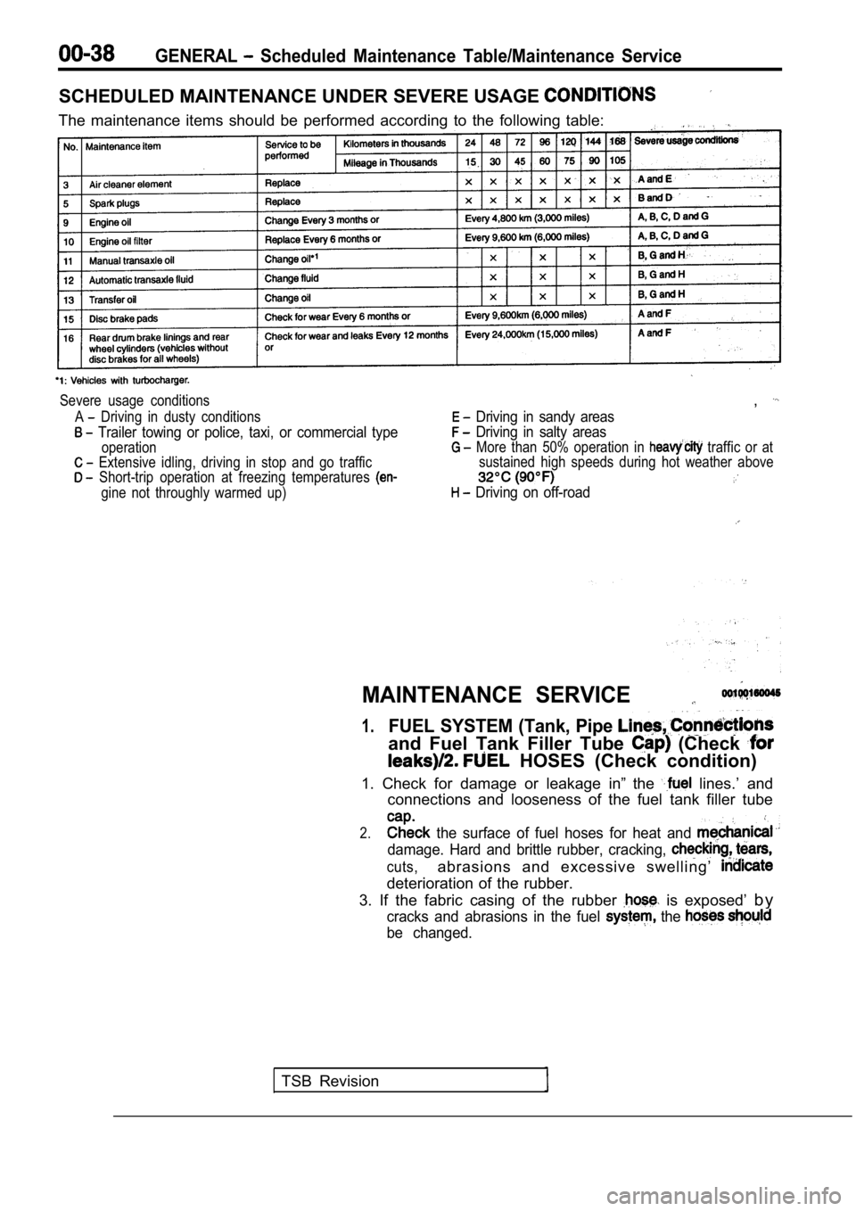
SCHEDULED MAINTENANCE UNDER SEVERE USAGE
The maintenance items should be performed according to the following table:
Severe usage conditions
A
Driving in dusty conditions
Trailer towing or police, taxi, or commercial type
operation
Extensive idling, driving in stop and go traffic
Short-trip operation at freezing temperatures
gine not throughly warmed up)
,
Driving in sandy areas
Driving in salty areas
More than 50% operation in traffic or at
sustained high speeds during hot weather above
Driving on off-road
MAINTENANCE SERVICE
1.FUEL SYSTEM (Tank, Pipe
and Fuel Tank Filler Tube (Check
HOSES (Check condition)
1. Check for damage or leakage in” the
lines.’ and
connections and looseness of the fuel tank filler t ube
2. the surface of fuel hoses for heat and
damage. Hard and brittle rubber, cracking,
cuts,abrasions and excessive swelling’
deterioration of the rubber.
3. If the fabric casing of the rubber
is exposed’ b y
cracks and abrasions in the fuel the
be changed.
TSB Revision
Page 106 of 2103
ENGINE OVERHAUL General Information
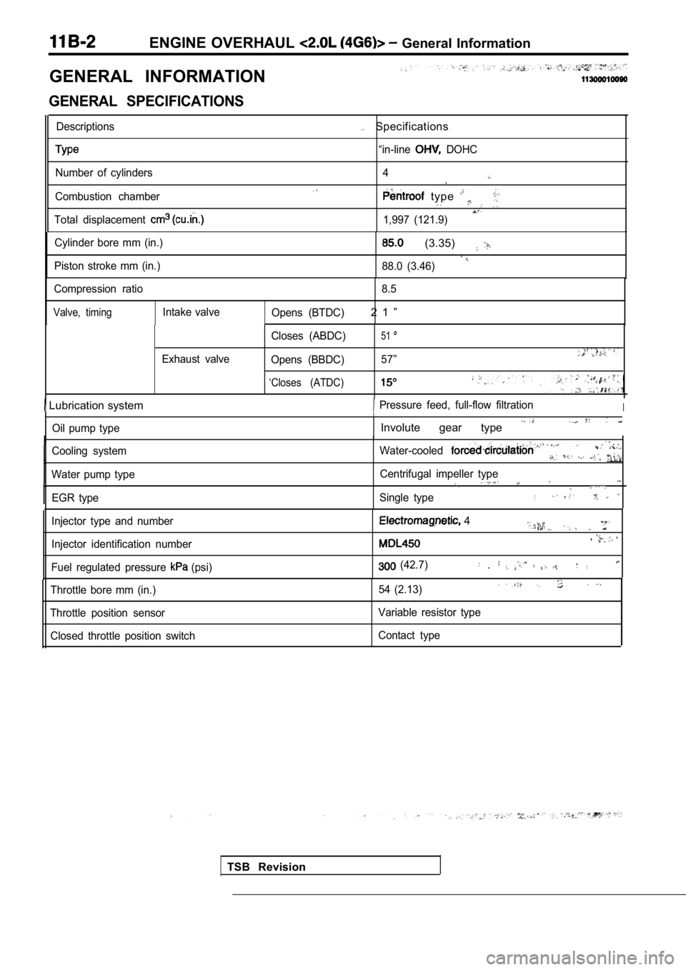
GENERAL INFORMATION
GENERAL SPECIFICATIONS
Descriptions
Number of cylinders
Combustion chamber
Total displacement
. . .Specifications
“in-line DOHC
4
type
1,997 (121.9)
Cylinder bore mm (in.)
Piston stroke mm (in.)
(3.35)
88.0 (3.46)
Compression ratio 8.5
Valve, timingIntake valve
Opens (BTDC)2 1 ”
Exhaust valve Closes (ABDC)
51
Opens (BBDC)
57”
‘Closes (ATDC)
Lubrication system Pressure feed, full-flow filtrationI
Oil pump type
Cooling system
Water pump type EGR type
I
Involute gear type
Water-cooled . .
Centrifugal impeller type
Single type,
TSB Revision
Injector type and number
Injector identification number
Fuel regulated pressure
(psi)
4
,
(42.7) .
Throttle bore mm (in.)
Throttle position sensor Closed throttle position switch 54 (2.13)
Variable resistor type
Contact type
Page 138 of 2103
11 ENGINE OVERHAUL Rocker
.
INSPECTION
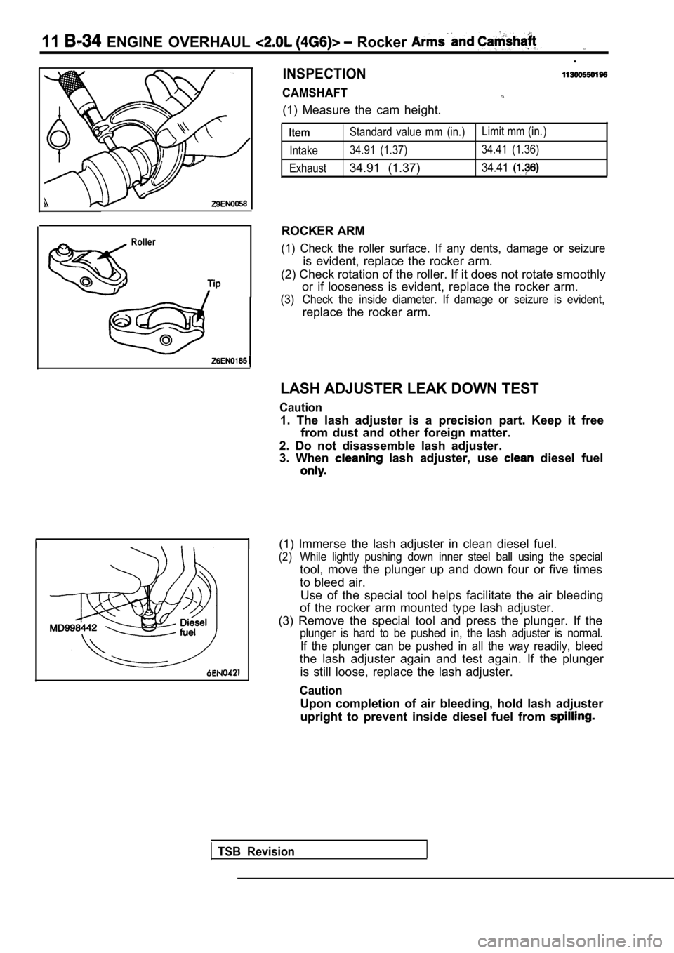
CAMSHAFT
(1) Measure the cam height.
Roller
Standard value mm (in.)Limit mm (in.)
Intake 34.91 (1.37) 34.41 (1.36)
Exhaust
34.91 (1.37)34.41
ROCKER ARM
(1) Check the roller surface. If any dents, damage or seizure
is evident, replace the rocker arm.
(2) Check rotation of the roller. If it does not ro tate smoothly
or if looseness is evident, replace the rocker arm.
(3) Check the inside diameter. If damage or seizure is evident,
replace the rocker arm.
LASH ADJUSTER LEAK DOWN TEST
Caution
1. The lash adjuster is a precision part. Keep it f ree
from dust and other foreign matter.
2. Do not disassemble lash adjuster.
3. When
lash adjuster, use diesel fuel
(1) Immerse the lash adjuster in clean diesel fuel.
(2)While lightly pushing down inner steel ball using t he special
tool, move the plunger up and down four or five tim es
to bleed air. Use of the special tool helps facilitate the air bl eeding
of the rocker arm mounted type lash adjuster.
(3) Remove the special tool and press the plunger. If the
plunger is hard to be pushed in, the lash adjuster is normal.
If the plunger can be pushed in all the way readily, bleed
the lash adjuster again and test again. If the plun ger
is still loose, replace the lash adjuster.
Caution
Upon completion of air bleeding, hold lash adjuster
upright to prevent inside diesel fuel from
TSB Revision
Page 342 of 2103
ENGINE OVERHAUL Rocker Arms Camshaft
I
INSPECTION
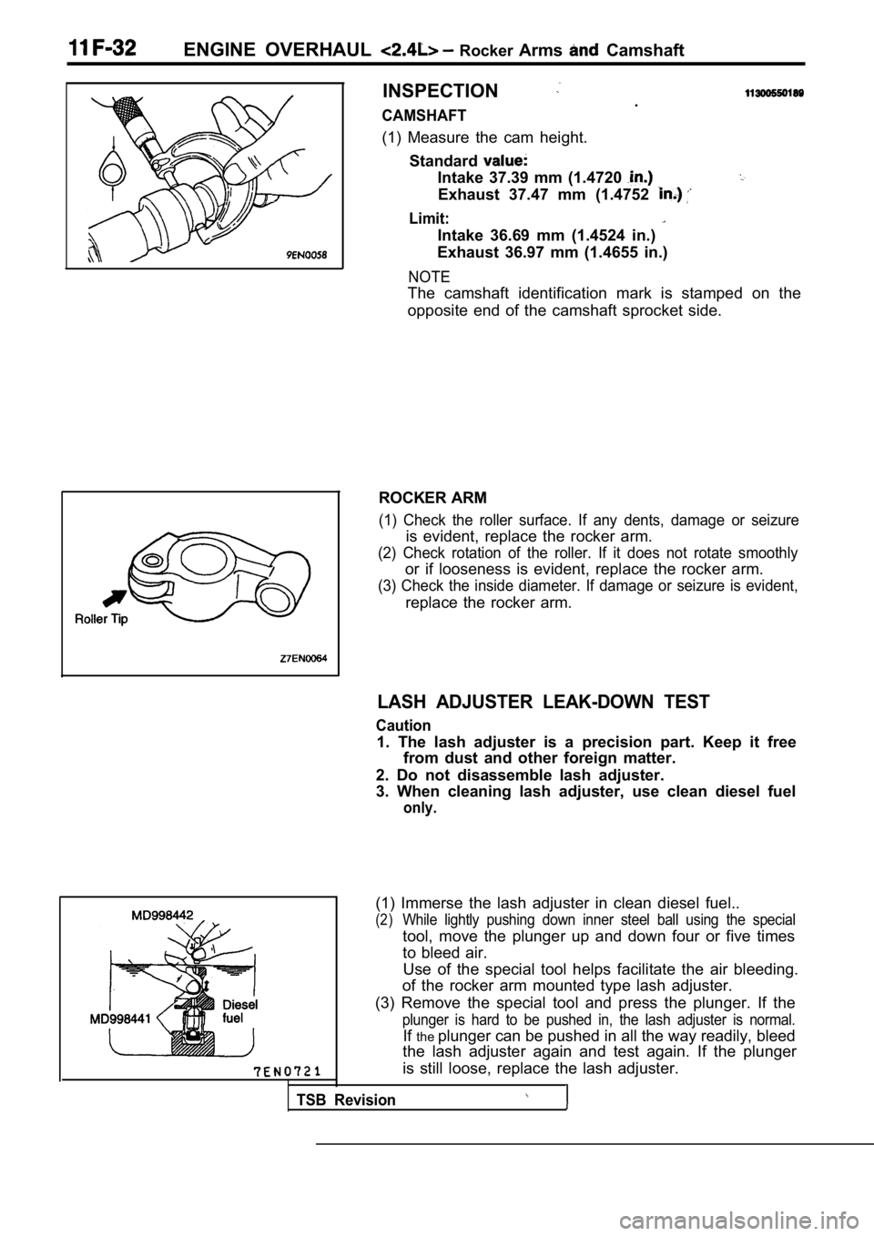
CAMSHAFT.
(1) Measure the cam height. Standard
Intake 37.39 mm (1.4720
Exhaust 37.47 mm (1.4752
Limit:
Intake 36.69 mm (1.4524 in.)
Exhaust 36.97 mm (1.4655 in.)
NOTE
The camshaft identification mark is stamped on the
opposite end of the camshaft sprocket side.
ROCKER ARM
(1) Check the roller surface. If any dents, damage or seizure
is evident, replace the rocker arm.
(2) Check rotation of the roller. If it does not rotate smoothly
or if looseness is evident, replace the rocker arm.
(3) Check the inside diameter. If damage or seizure is evident,
replace the rocker arm.
LASH ADJUSTER LEAK-DOWN TEST
Caution
1. The lash adjuster is a precision part. Keep it f ree
from dust and other foreign matter.
2. Do not disassemble lash adjuster.
3. When cleaning lash adjuster, use clean diesel fu el
only.
Use of the special tool helps facilitate the air bleeding.
of the rocker arm mounted type lash adjuster.
(3) Remove the special tool and press the plunger. If the
plunger is hard to be pushed in, the lash adjuster is normal.
Ifthe plunger can be pushed in all the way readily, bleed
the lash adjuster again and test again. If the plun ger
is still loose, replace the lash adjuster.
TSB Revision
(1) Immerse the lash adjuster in clean diesel fuel. .
(2)While lightly pushing down inner steel ball using t he special
tool, move the plunger up and down four or five tim es
to bleed air.
Page 374 of 2103
ENGINE LUBRICATION General Information/Lubricants
G E N E R A L I N F O R M A T I O N
The lubrication method is a fully force-fed, full-f low
filtration type.
ENGINE OILS
Health Warning
Prolonged and repeated contact with mineral oil
will result in the removal of natural fats from the
skin, leading to dryness, irritation and dermatitis .
In addition, used engine oil
potentially
Recommended Precautions
The most effective precaution is to adapt working
practices which prevent, as far as practicable, the
risk of skin contact with mineral oils, for example
by using enclosed systems for handling used engine
oil and by degreasing components, where
practicable, before handling them.
Other precautions:
lAvoid prolonged and repeated contact with oils,
particularly used engine oils.
l Wear protective clothing, including impervious
gloves where practicable.
l Avoid contaminating clothes, particularly
underpants, with oil.
l Do not put oily rags in packets, the use of
overalls without pockets will avoid this.
l Do not wear heavily soiled clothing and
oil-impregnated foot-wear. Overalls must be
cleaned regularly and kept separate from
personal clothing.
LUBRICANTS
harmful contaminants which may cause skin cancer.
Adequate means of skin protection and washing
facilities must
provided.
Where there is a risk of eye contact, eye protection should be worn, for example,
chemical goggles or face shields; in addition
an eye wash facility should be provided.
Obtain First Aid treatment immediately for open
cuts and wounds.
Wash regularly with soap and water to ensure
all oil is removed, especially before
cleansers and nail brushes will help). After
cleaning, the application of
containing lanolin to replace the natural
oil is advised.. .
Do not use gasoline, kerosine, diesel fuel,
oil, thinners or solvents for cleaning skin.
Use barrier creams, applying them before each
work period, to help the removal of oil from
the skin after work.
If skin disorders develop, obtain medical advice
without delay.
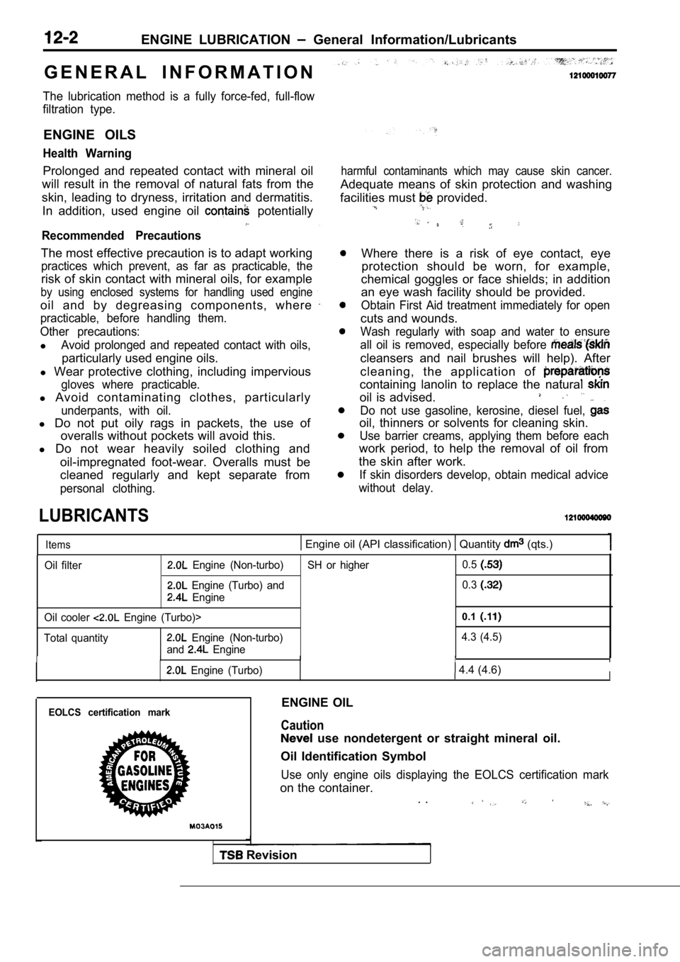
Items Engine oil (API classification) Quantity (qts.)
Oil filter Engine (Non-turbo)
Engine (Turbo) and
Engine
Oil cooler
Engine (Turbo)>
Total quantity
Engine (Non-turbo)
and
Engine SH or higher
0.5
0.3
0.1
4.3 (4.5)
IIIII
Engine (Turbo) 4.4 (4.6)I
EOLCS certification markENGINE OIL
Caution
use nondetergent or straight mineral oil.
Oil Identification Symbol
Use only engine oils displaying the EOLCS certifica tion mark
on the container.
. .
Revision
Page 384 of 2103
ENGINE (NON-TURBO)>
DIAGNOSTIC TEST MODE
l When an abnormality is detected in one
of the sensors or actuators related to
emission control, the CHECK
MALFUNCTION INDICATOR LAMP
nates as a warning to the driver.
l When an abnormality is detected in one
of the sensors or actuators, a diagnostic
OTHER CONTROL FUNCTIONS
t r o u b l e c o d e
a b n o r m a l i t y i s o u t p u t .
lThe RAM data inside the PCM that is
to the sensors and
by means of the scan tool.
In addition, the actuators can be controlled
under certain circumstances. . ,
1. Fuel Pump Control
Turns the fuel pump relay ON so that current
is supplied to the fuel pump while the engine
is cranking or running.
2. A/C Compressor Clutch Relay Control Turns the A/C compressor clutch ON and
OFF.
3. Fan Relay Control
The radiator fan and condenser fan speeds
are controlled in response to the engine
coolant temperature and vehicle speed. 4. Generator
Controls the generator in order
to control the generated current.
5. Engine Speedometer or Tachometer
Control.
Sends a pulse signal which ‘corresponds
to the engine speed to the’ speedometer
unit..
6. Evaporative Emission Purge
C o n t r o l
Refer to GROUP 17.
7. Electric EGR Transducer Solenoid Control Refer to GROUP 17.
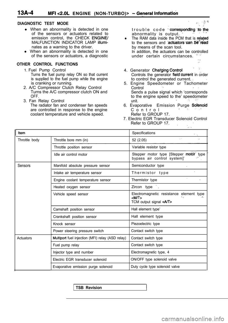
Throttle body
Sensors
Actuators
Specifications
Throttle bore mm (in) 52 (2.05)
Throttle position sensor Variable resistor type
Idle air control motor
Stepper motor type [Stepper type
bypass air control system]’,
Manifold absolute pressure sensor Semiconductor type
Intake air temperature sensorT h e r m i s t o r t y p e
Engine coolant temperature sensorThermistor type .
Heated oxygen sensorZircon type .
Vehicle speed sensorElectromagnetic resistance element type
TCM output signal
Camshaft position sensor Hall element type’
Crankshaft position sensor
Hall element type
Knock sensor Piezoelectric type
Power steering pressure switch Contact switch type
fuel injection (MFI) relay (ASD relay)
Contact switch type
Fuel pump relay Contact switch type
Injector type and number Electromagnetic type, 4
Electric EGR transducer solenoid ON/OFF type solenoid valve
Evaporative emission purge solenoid Duty cycle type solenoid valve
TSB Revision